BastelBaus
Concept
My last PC was very noisy and old so I had the dream to build a complete passive PC. After some search I thought that it schould be possible. Follow the logs to see how I finally succeeded. Let's start with some interessting links I found in the internet:
- Asian description of an alike build: link
- Companies offering passive PCs: e.g. link, link
- A nice YouTube channel: link
- A german project in a forum: link
In my build I did not use an external graphics card and relied only on the build in capbabilities of the AMD Ryzen 7 which I also found to be very power efficient. For my kind of applications this is absolutely sufficient.
Component & cost estimate (2023)
This list should give you an overview about the components used and the cost associated. I did not counted the shipping costs nor the heatpipes I scrapped in between :-)
- PC Electronic Components
- CPU: AMD 7 Ryzen 7700x
- Motherboard: asus prime 650m-a wifi
- RAM: G.Skill Flare X5 schwarz DIMM Kit 32GB
- SSD: KINGSTON SFYRD2000G + Passive Cooler
- Silverstone SST-NJ700-80-Plus-Titanium
- DVD: HL-DT-ST DVDRAM GTC2N
- USB Front Pannel: GG 18019 Card Reader, intern, 3,5", USB 3.1, SD, Micro SD
- Graphic Card: none, used internal graphics
- Housing & Cooler (~250€)
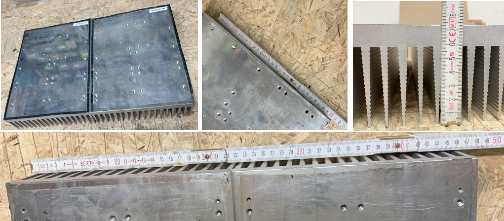
- 2x Coolers (~90€, found on ebay incl shipping)
- 5x 6mm Heatpipes [400mm and 300mm] (35€ plus shipping) possible source
- 10x (10mmx20mmx5mm) + 2x Copper (60mmx50mmx10mm) blocks for heat pipe mount to cooler and CPU respectively (40€ plus shipping) possible on ebay
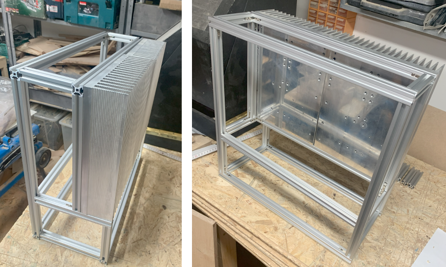
- Alu profiles (20mmx20mm, ~6m) and mounting angles (~45€ plus shipping) possible source
- Smaller stuff:
- alu blades for mounting (was scrap lying arround)
- Thermal paste (10€)
- Generic screws, us screws for CPU copper block mount and distance bolts (5€)
- Additional mini Alu Cooler fro CPU (8€)
- SlimDVD adapter cable
- Reset/Power Button
- T measurement setup (used only for debugging)
- Arduino Nano
- 5x T-sensors
- Box (2€)
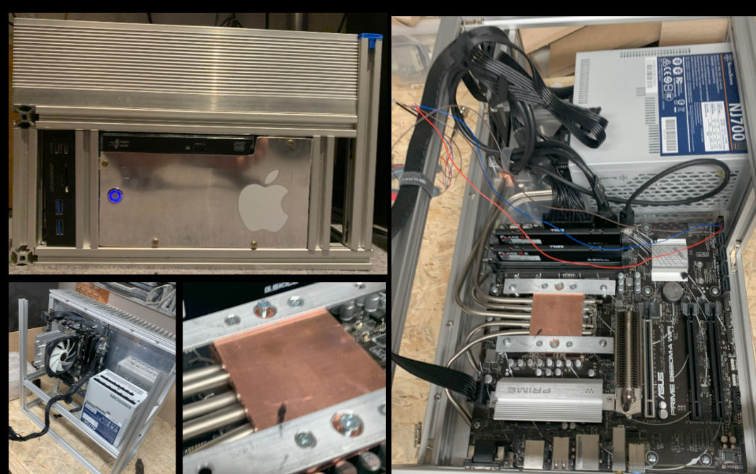
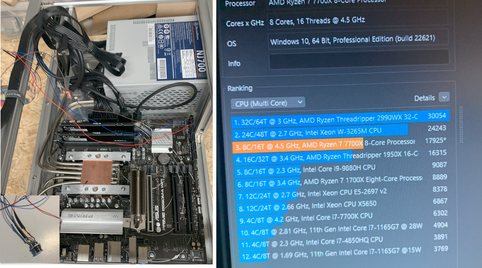
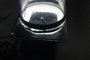
Some PICs of my final full passive AMD Ryzen 7 7700X PC setup
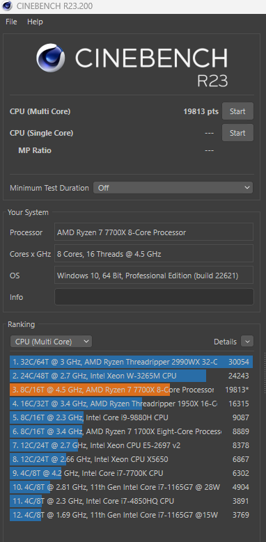
reaching nearly 20.000pnts on cinebench R23
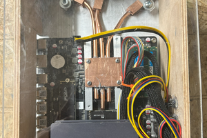
- The orientation of the CPU towards the mounting points of the heat pipes seams to be important. CPU should be below (gravity) the mounting points on the cooler.
- Be carefull+carfull+carefull when bending the pipes
 The final benchmark results are really nice and the only noiseI I spotted was from my (old) monitor when I did not turn off the sound card :-) Initial test over 19.000 points in Cinebench R23 and also the stability test is only minor points below 19.000.
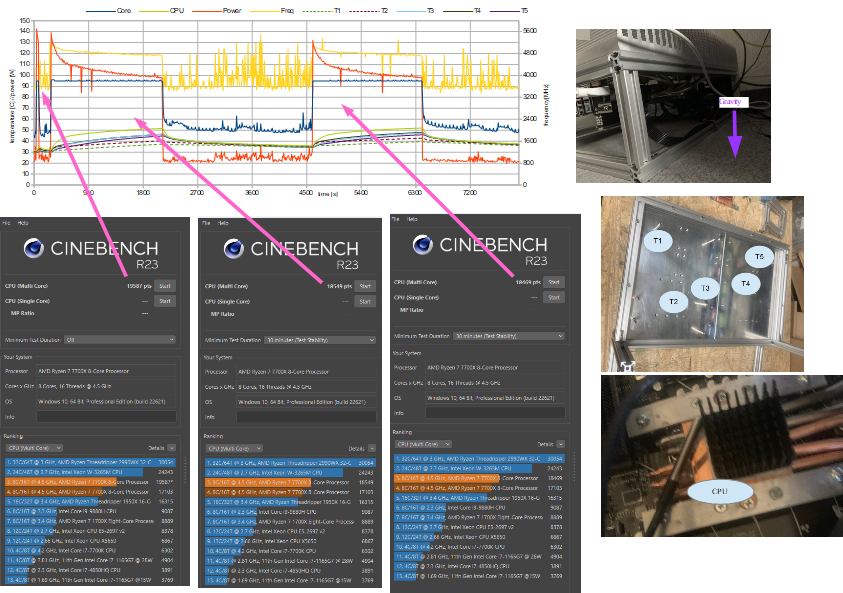
 I glued temperature sensors to several positions of the alu cooler and the copper blocks and used an Arduino Nano to measure the temperature at different positions.
 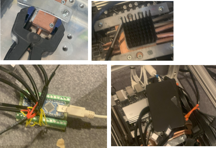 I had teh feeling that some of teh pipes did not work correctly and asked for help in the internet. After some de-mounting and remounting, bending of 3 new heat pipes and finding that the orientation of the PC was quite important for the performance, I finally solved my challenges. Please see here for more information on the debugging:
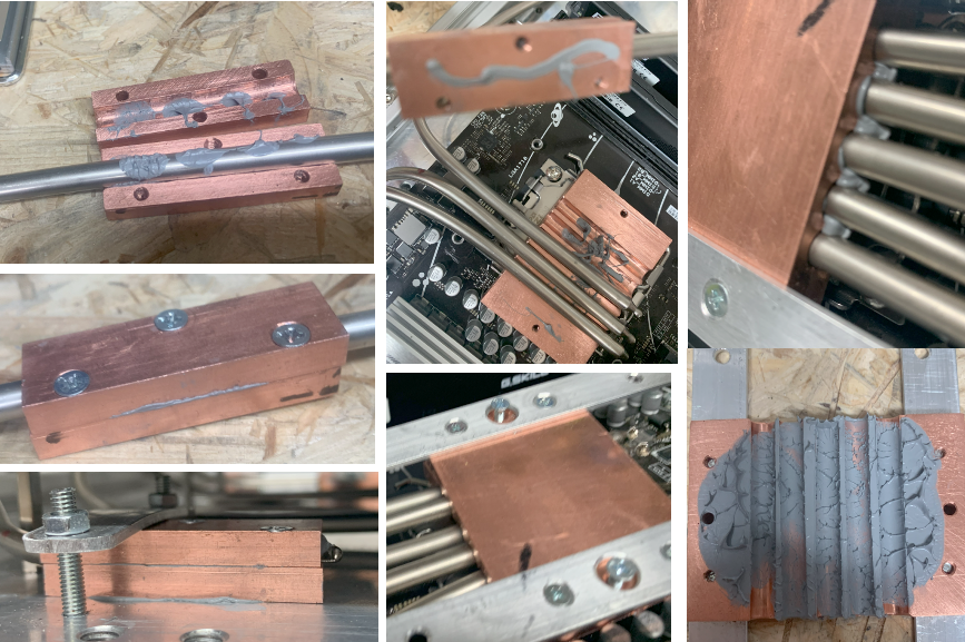
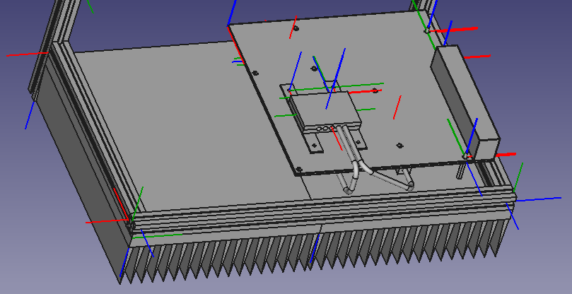
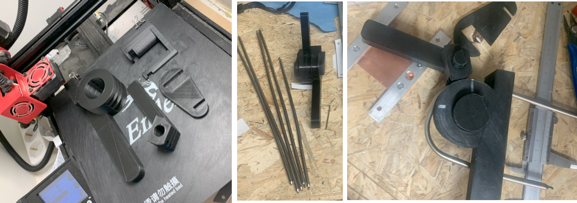 Step by step I adjusted all five heatpipes not to touch anything and form a good connection from the CPU towards the cooler:
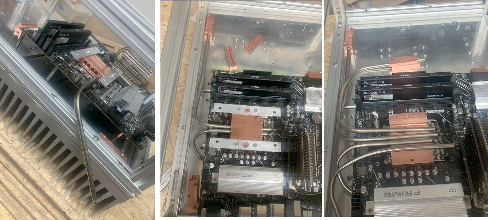 To fix the copper blocks I also used a small piece of alu with holes and drilled screw holes inside the alo cooler.
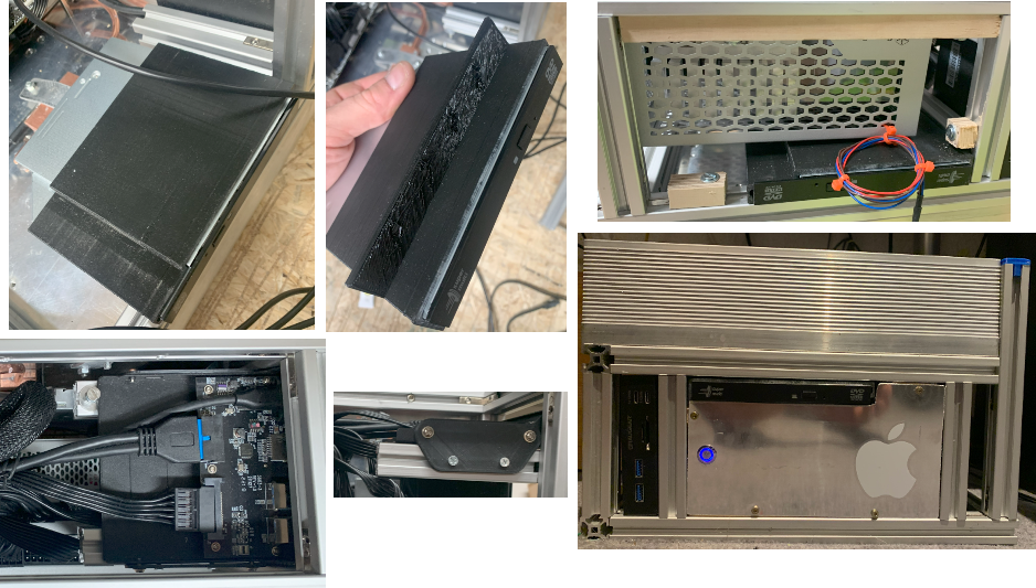
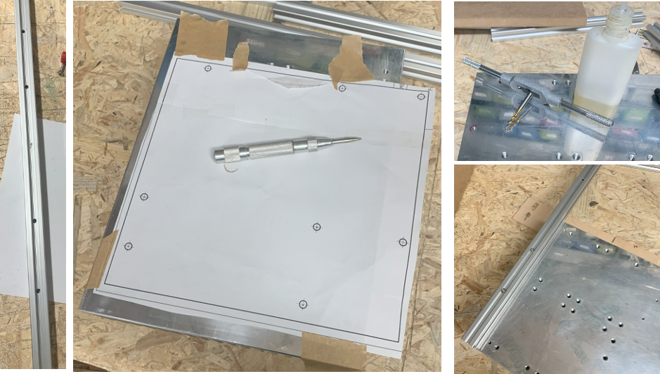
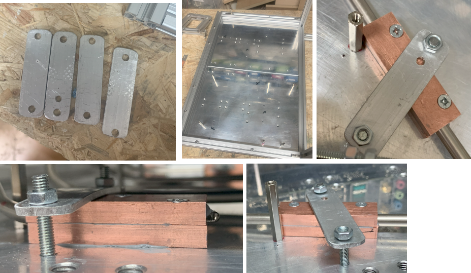
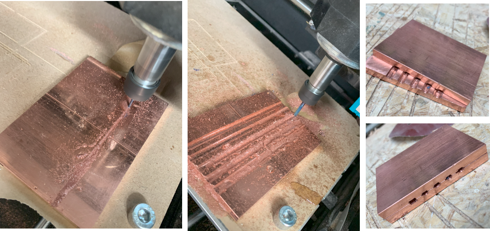 Putting the two blocks together and mounting within a wise, I was able to drill the holes in the exact diameter I needed. After the first hole was drilled, a drill bit was used to avoid that both copper blocks moved while drilling.
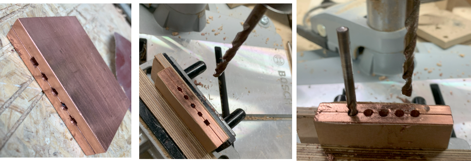 Cleaning the holes, tapping screw holes to press both blocks together was the next step for the CPU copper block adapter.
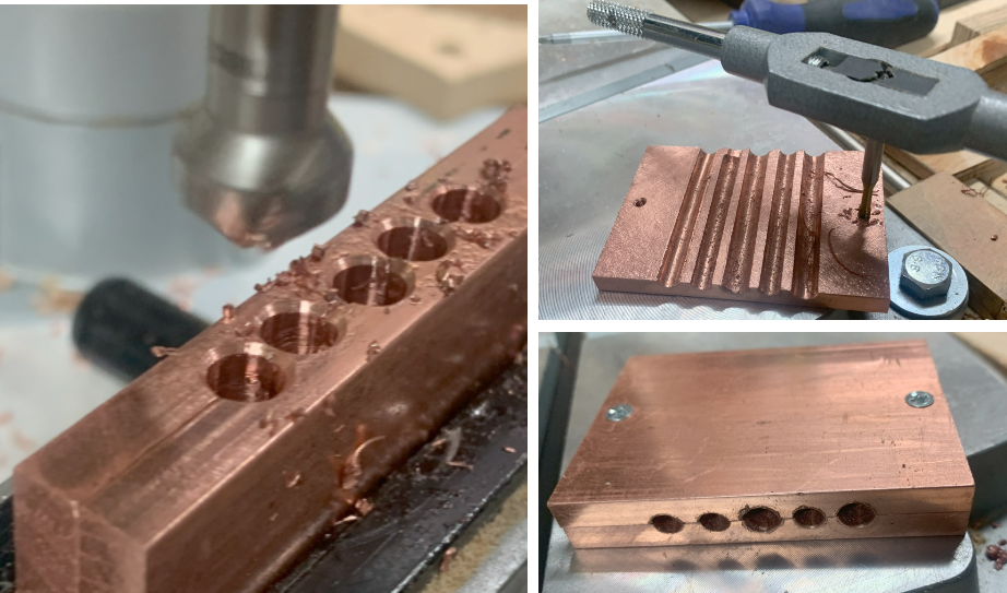 Finally I used a bit of scrap aluminium to make a fixture of teh copper block which I could then screw into the holes of the mainboard for the cooler.
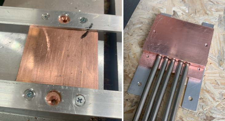 The smaller copper blocks to mount the heat pipes to the alu ribbon cooler I drilled directly which also lead to the loss of one of the drill bits :-)
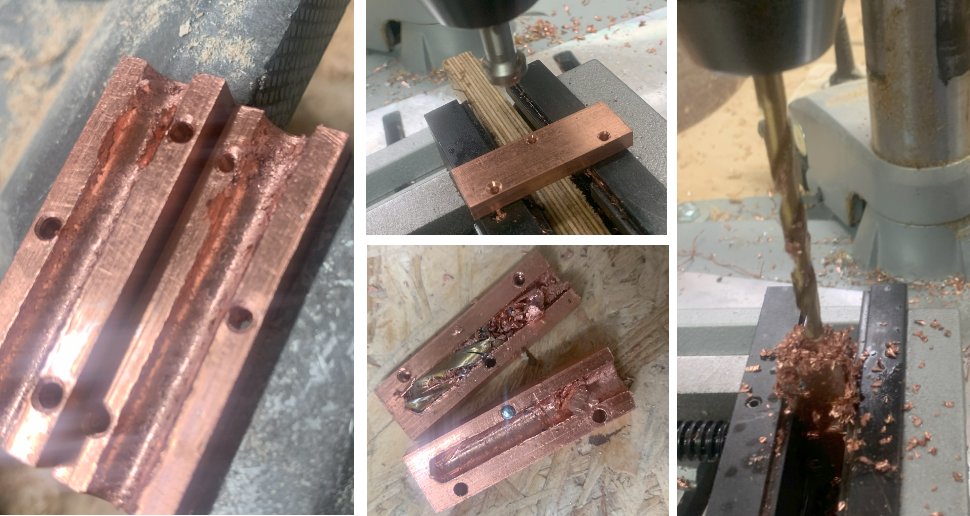
 With some distance bolts I mounted the PCB to the alu cooler (in fact only to one of both, not to induce mechanical stress to the board when the coolers would relative move.
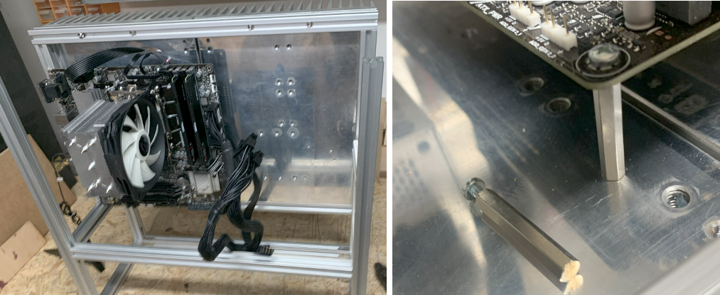 To mount the power supply, I used some spare aluminium sheets, drilled holes and fixated the sheets inside the alu profiles
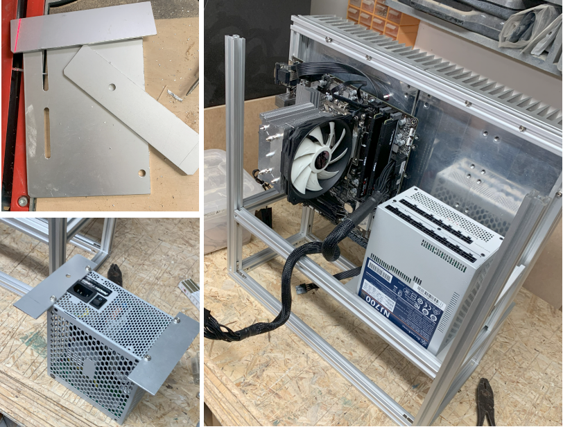
 NuclearPhoenix