 Tamas Feher
Let's look at the central control circuitry next.
If we take a look at the subsystem breakdown in BJR_LOG_02, we can see the central control circuit already has it's inputs and outputs defined. The following figure is a context diagram, which shows the Control Circuit and it's interfacing blocks.
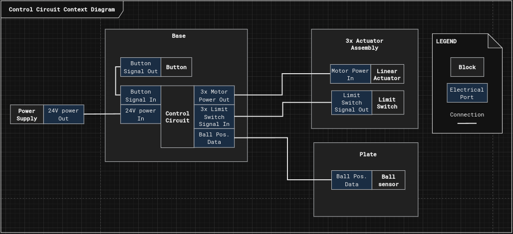
Let's go over the interfaces and form them into requirements:
1. The Central Control Circuit shall be powered by 24VDC power
2. The Central Control Circuit shall control 3 stepper motors with 0.6A current per winding
3. The Central Control Circuit shall listen to the input of 3 endstop NO (normally open) switches mounted at the end of the actuators.
4. The Central Control Circuit shall listen to the input a user button
5. The Central Control Circuit shall communicate with the plate through I2C protocol (It hasn't been established yet how the plate will communicate with the base, a later log will go into more details on the why and the hows.)
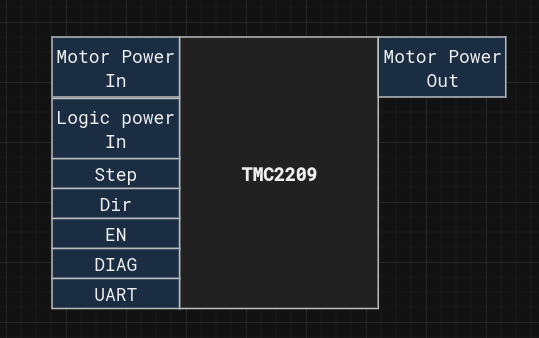
The main component that controls the stepper motors is the TMC2209. It has been selected for it's StealthChop2 and CoolStep features which provides noise free operation at lower speeds and reduced current use in idle mode, which helps with heating of the actuators.
The datasheet helps identifying the main interfaces of this device, which are:
- Motor power in: 24VDC in our case
- Logic power in: 3.3VDC in our case
- Step/Dir: traditional stepper motor driver interface, where the motor executes a step every time a falling edge is detected on the Step line. The direction of the step is determined by the Dir input.
- EN: shorts the motor coils, and disables the output. It's useful for the off state and initialisation.
- Diag: pin offers feedback to the controller if anything went wrong during operation.
- UART: is a one pin serial interface to set the drivers internal registers.
Now we have all the necessary components to devise a block diagram for the circuit:
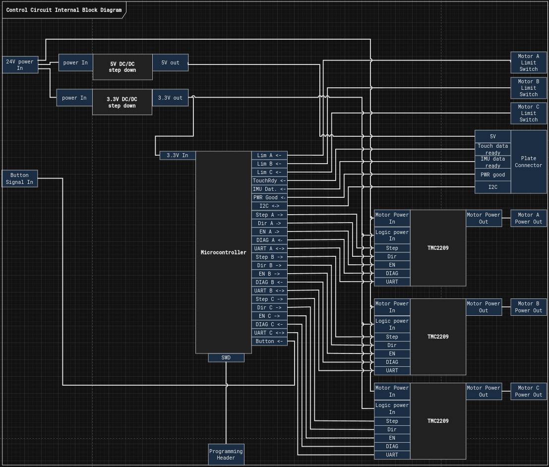
In this circuit a single microcontroller hosts all the computation needed. Based on the block diagram it needs to be capable of hosting:
- 9 Digital outputs
- 10 Digital inputs
- 3 UART channels
- An I2C bus
- SWD programming
Given these requirements I chose the STM32F446RE microcontroller.
There is no elaborate reason why I chose this one, I just had a couple of these lying around in a drawer.
With this the Circuit is ready prototyping and the software to be started.
If you're interested in the project, give it a like, and leave a comment on what part you would like to see next.
Discussions
Become a Hackaday.io Member
Create an account to leave a comment. Already have an account? Log In.