 Michael Gardi
My SMD Experience
My first experience using SMD parts went well. After practicing on some tiny 0402 resistors, the hall effect sensor parts seemed absolutely gigantic. This board was basically a "Hello, World." for SMD fabrication. I probably could have hand soldered the parts (maybe) or applied the solder paste by hand, but I was looking for the full SMD experience. So I designed and printed a jig to hold the PCB.
I had a stencil created along with the PCBs and used this rig to setup ten Tile Button Sensor panels. Then I used the reflow oven at Kwartzlab to finish the parts. A big thanks to Erin and Konstantin at Kwartzlab for their help getting me going on this.
Tile Holder Button Assembly
To make the PCB version of the Tile Holder Button:
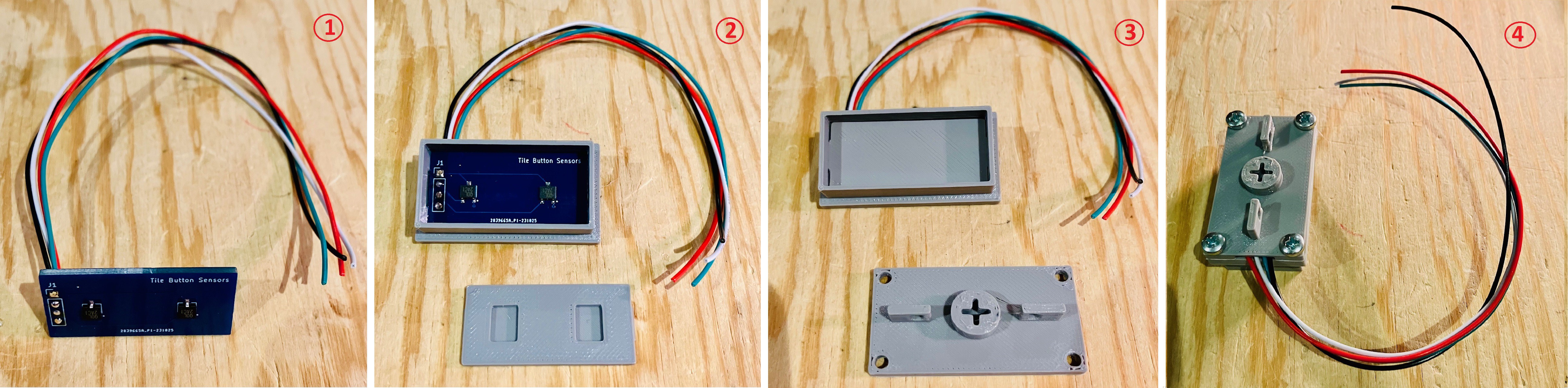
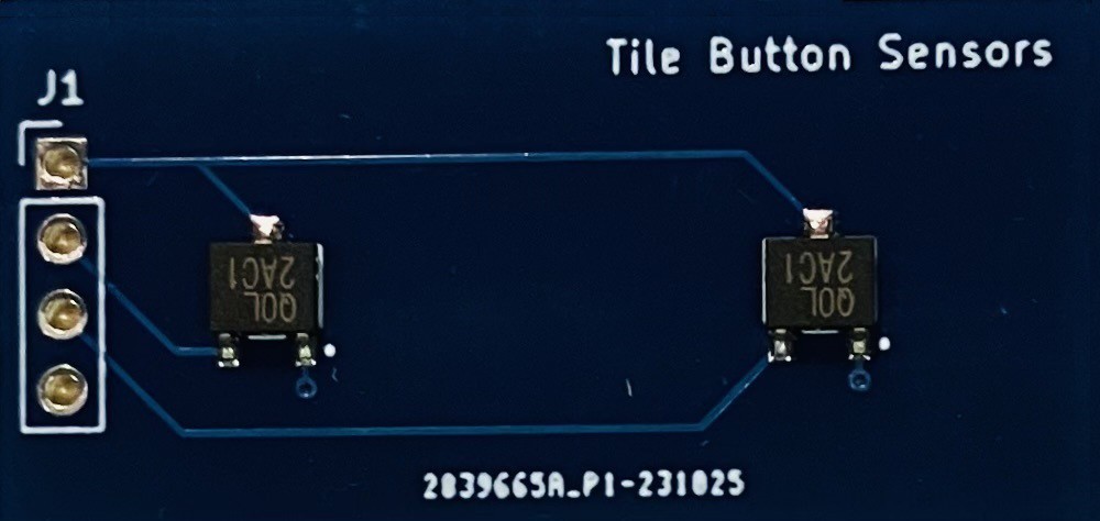
- Solder four leads to the PCB header from the bottom as pictured above. The square via (pin 1) on the header is ground and the opposite side is power. The two middle pins are for the hall effect sensor outs.
- Slide the leads through the slot in the bottom of the Tile Holder Button Top.
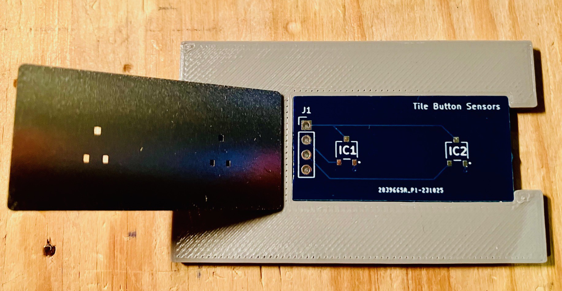
- Install the PCB Holder with the cutouts facing down. The tabs on the short side of the PCB holder should securely snap into the groves on the inside of the tile holder top.
- Attach the Tile Holder Button Bottom with four M3 x 6 mm bolts making sure that the wires are routed through the wiring channel provided.
Testing
I still have a pro Micro setup to test Tile Buttons. I wired up the new Tile Holder Button.
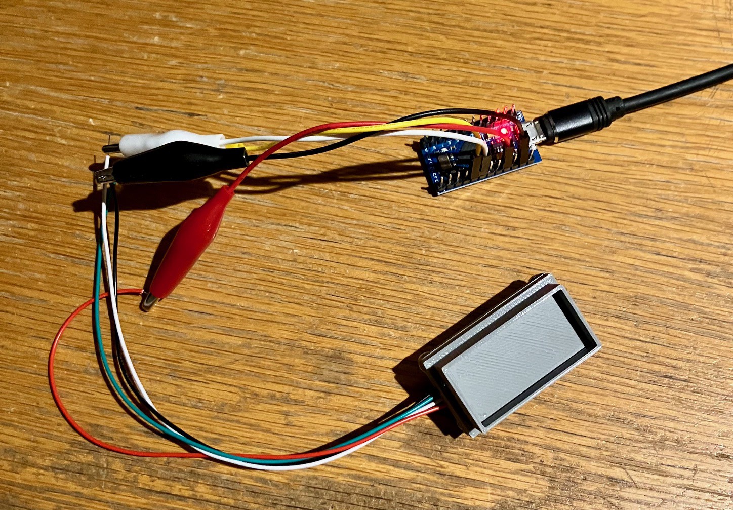
I ran my simple button testing Arduino sketch and dropped in one of my calibration tiles and:
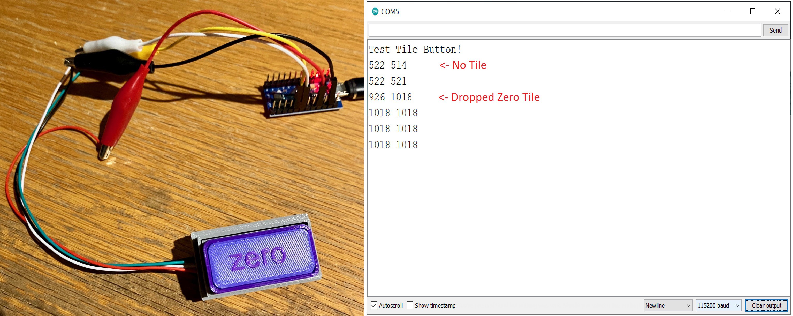
"YES!" it works, quickly followed by "OH, that's a problem.".
Whoops
I really should have though this through a bit, especially before I created the new tiles that I wrote about in the previous log entry. While I was careful to make sure that the EQ-430L SMD hall effect sensors were linear and bipolar like the SS49E through hole parts I was using, I paid no attention to the sensor sensitivity. It turns out that the SMD parts that I purchased are WAY more sensitive to magnetic fields than the through hole parts. This may have been exacerbated by my better aligning the sensor "sweet spot" with the center of the magnets for this new version of the tile button.
What does this mean? Well all of my existing tiles overpower the new sensor and return only 0 (GND) or 1018 (maxVCC) values if present depending on the polarity of the magnet. The neutral value with no magnets is still in the low 500s. How can this be fixed?
Recalibrating the Tiles
My existing tiles use two 6 mm x 1.8 mm cylindrical neodymium magnets per sensor. For the new sensor I had to go back to the drawing board to find magnets more suitable to increased sensitivity. I have quite a few cylindrical magnets of various sizes, so I started by manually holding them in turn above the new sensor, moving them closer and further away, while monitoring the values returned by the Test Tile Button! sketch. It wasn't until I got to my smallest magnet, 3 mm x 1.6 mm, that I found one that looked like it would work.
I did some further testing to verify these smaller magnets. I created some test tiles to hold these magnets at various distances from the sensors.
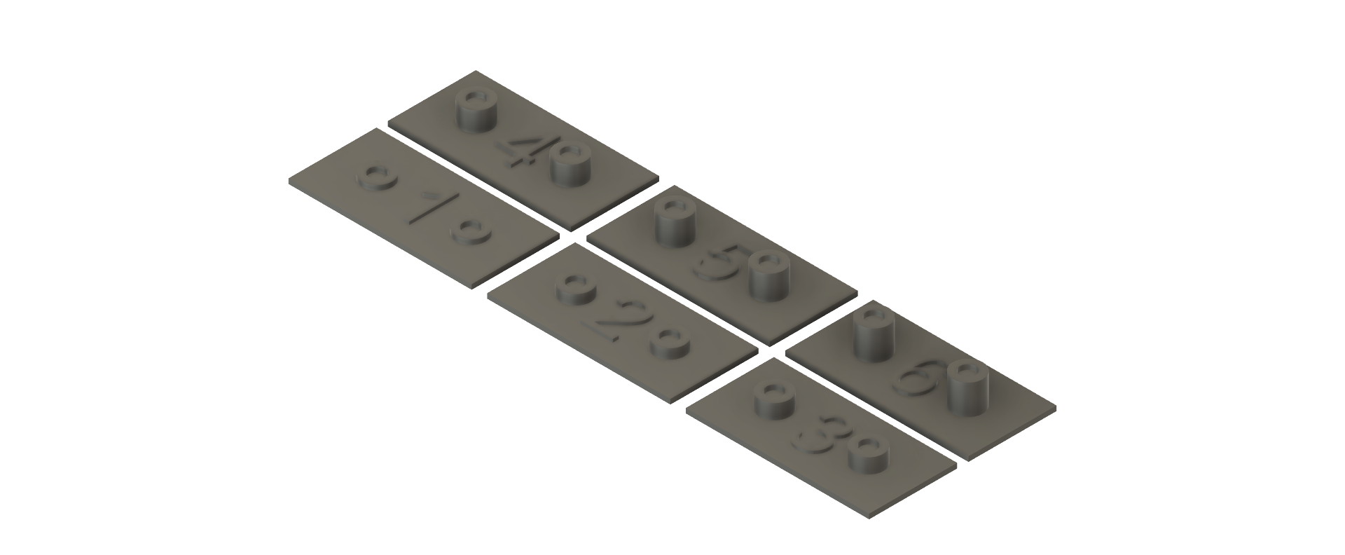
The numbers on the tiles indicate the distance from the sensor (in mm). Using these test tiles and the tile button holder just assembled I get the following values.
| Tile # / Distance | Polarity Value | Reverse Polarity Value |
|---|---|---|
| 1 mm | 1018 - 1018 | 0 - 0 |
| 2 mm | 895 - 877 | 100 - 105 |
| 3 mm | 750 - 729 | 254 - 280 |
| 4 mm | 642 - 636 | 341 - 364 |
| 5 mm | 562 - 588 | 389 - 405 |
| 6 mm | 549 - 569 | 419 - 428 |
These look pretty reasonable with a good separation between the readings based on distance. So the fix wasn't too bad. I just had to create a new set of magnet holders for the new magnets.
Of course this means that tiles created for this version of the MacroPad will not be compatible with the previous versions, and that the tiles that I made in my last log post are only useful now for those older versions. Not ideal but I can live with it.
Making Some New Calibration Tiles
I printed some Tile Bases, a couple of sets of the new PCB Magnet Holders, and some Tile Tops. I'm using up my orange filament left over from Halloween.
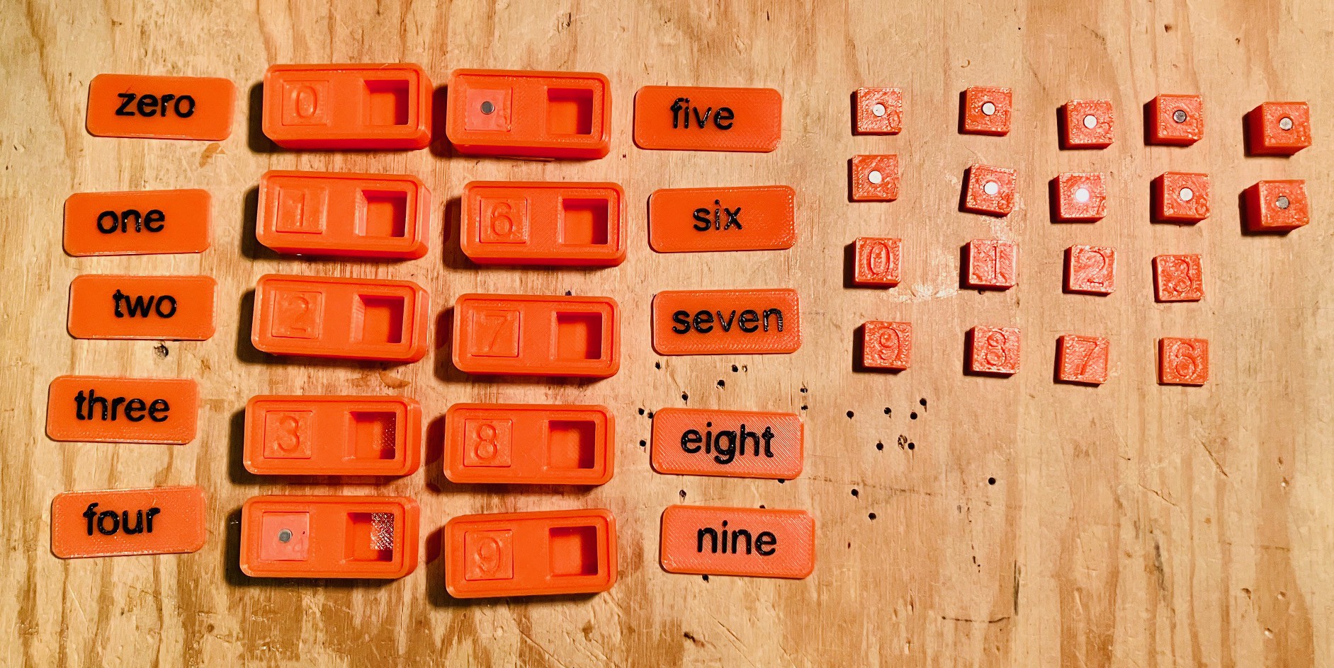
Here I am about half done. The magnets inserted into the 0-4 magnet holders have the opposite polarity of the magnets inserted into the 5-9 holders. I used a small piece of thin two sided tape to hold the magnets in and join the top and bottom parts of the magnet holders, then inserted them into the Tile Bases. Once they test out OK I'll add the labeled tops to complete the calibration set.
Discussions
Become a Hackaday.io Member
Create an account to leave a comment. Already have an account? Log In.