Close
0%
0%

MacroPad With Tile Holder Buttons PCB Edition

Not quite done with my tile based MacroPads. I'm making one more version to tighten up the design and make reproduction easier.

Similar projects worth following
With the previous version of my MacroPad With Tile Holder Buttons (https://hackaday.io/project/193117-macropad-with-tile-buttons) I found that wiring the Tile Holder Buttons was a pain and represents I think the weak point in the build. This is especially true since repeatedly pressing the buttons is going to put stress on the solder joints inside. Perhaps some hot glue would have help.

Sure enough I had a button failure after a couple of days. So I decided to make small PCBs for the buttons, and while I'm at it I decided to do a PCB for the main part as well. I don't know if anyone will ever want to build a MacroPad With Tile Buttons, but the dead bug wiring would probably scare them off if they did. With PCB's it will be a piece of cake.

Overview

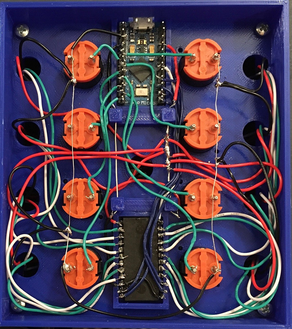
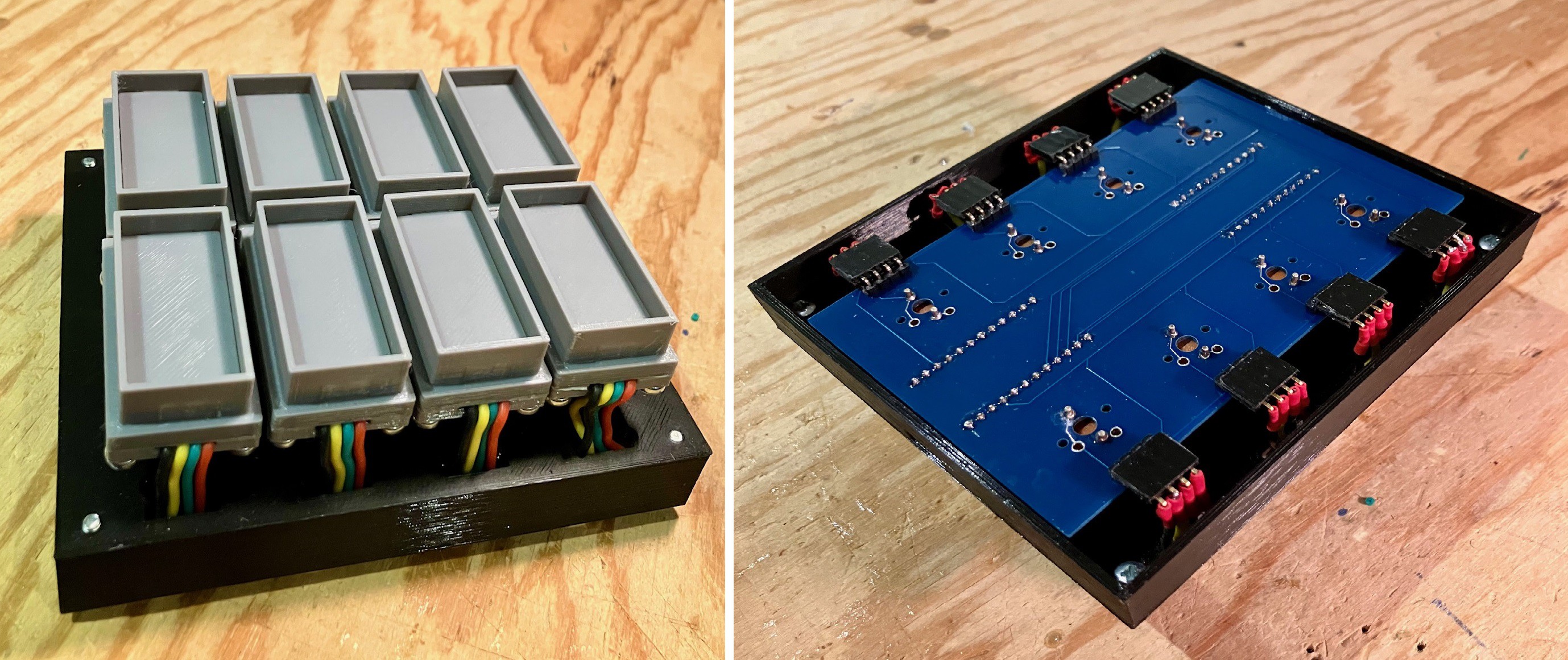
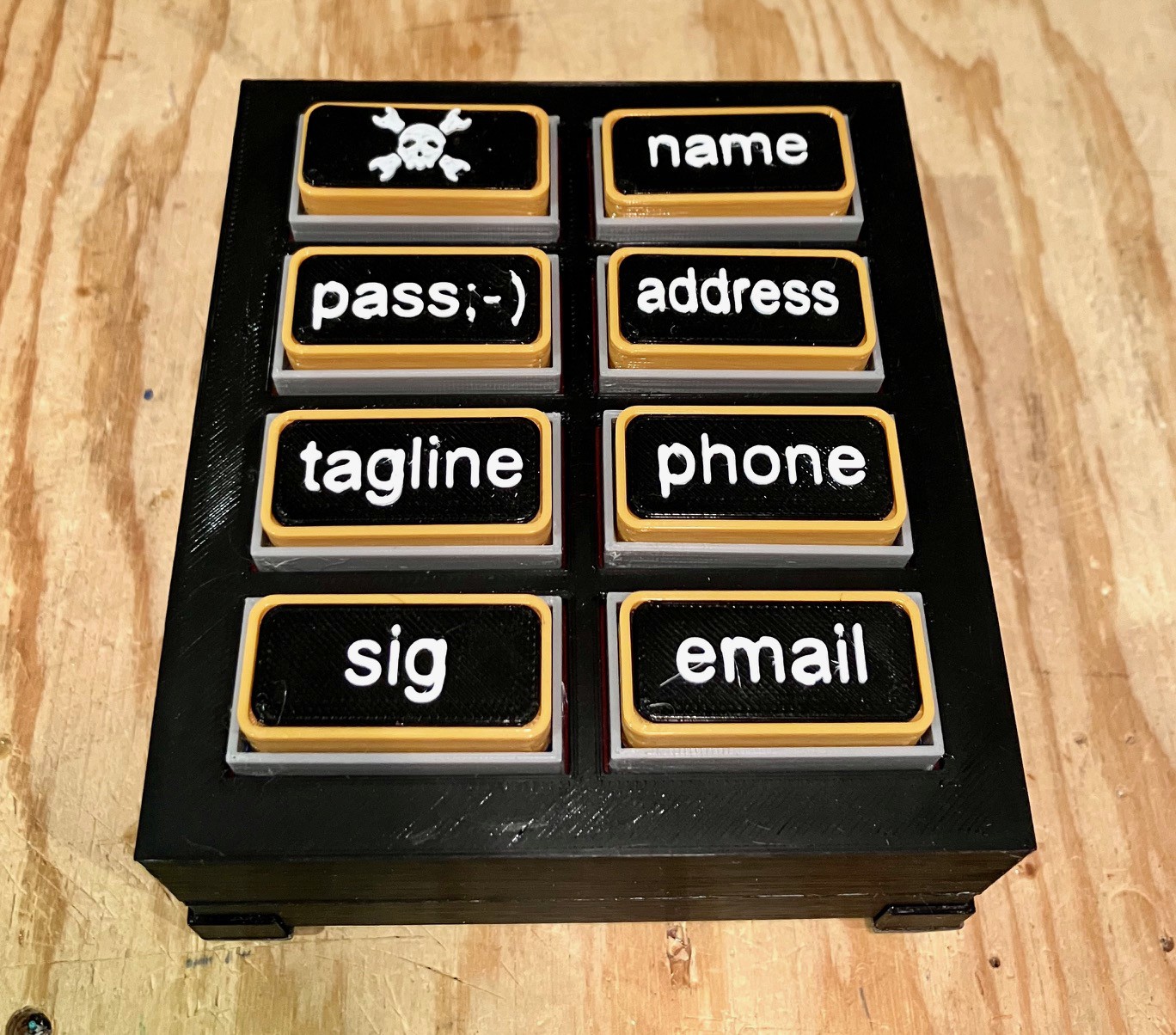
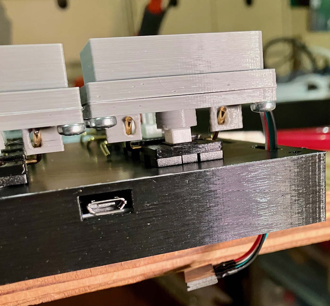
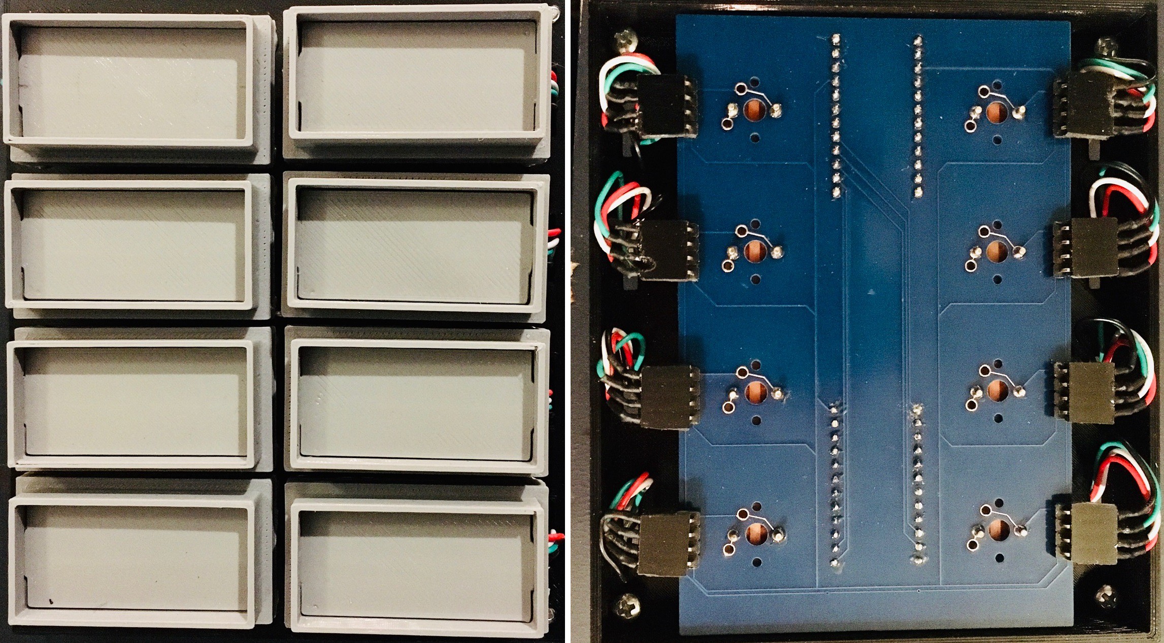
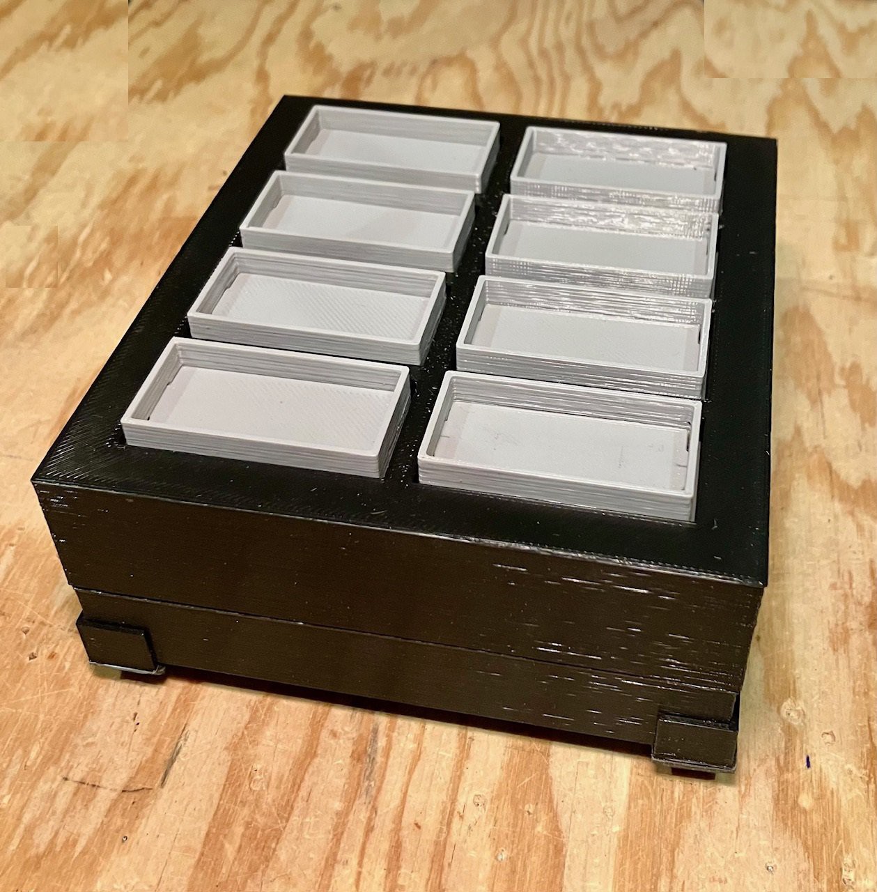
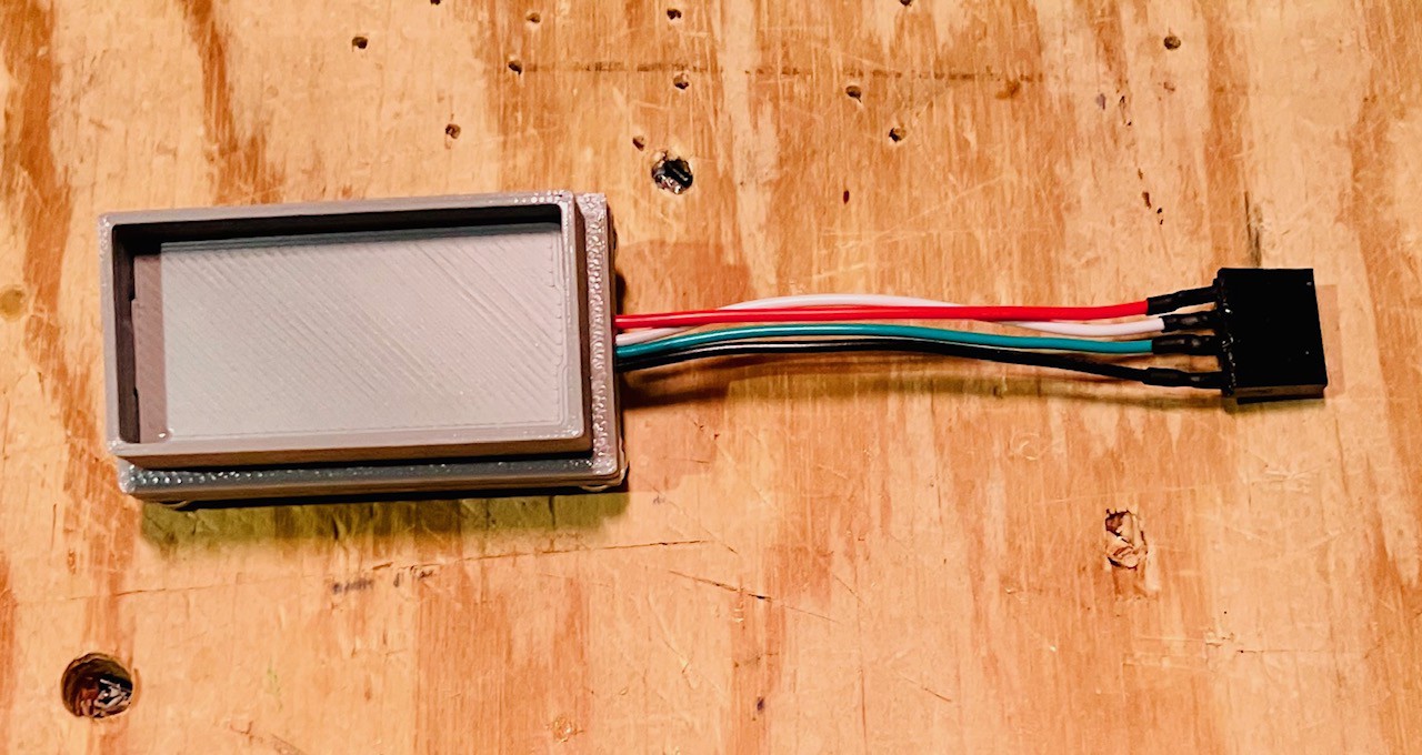
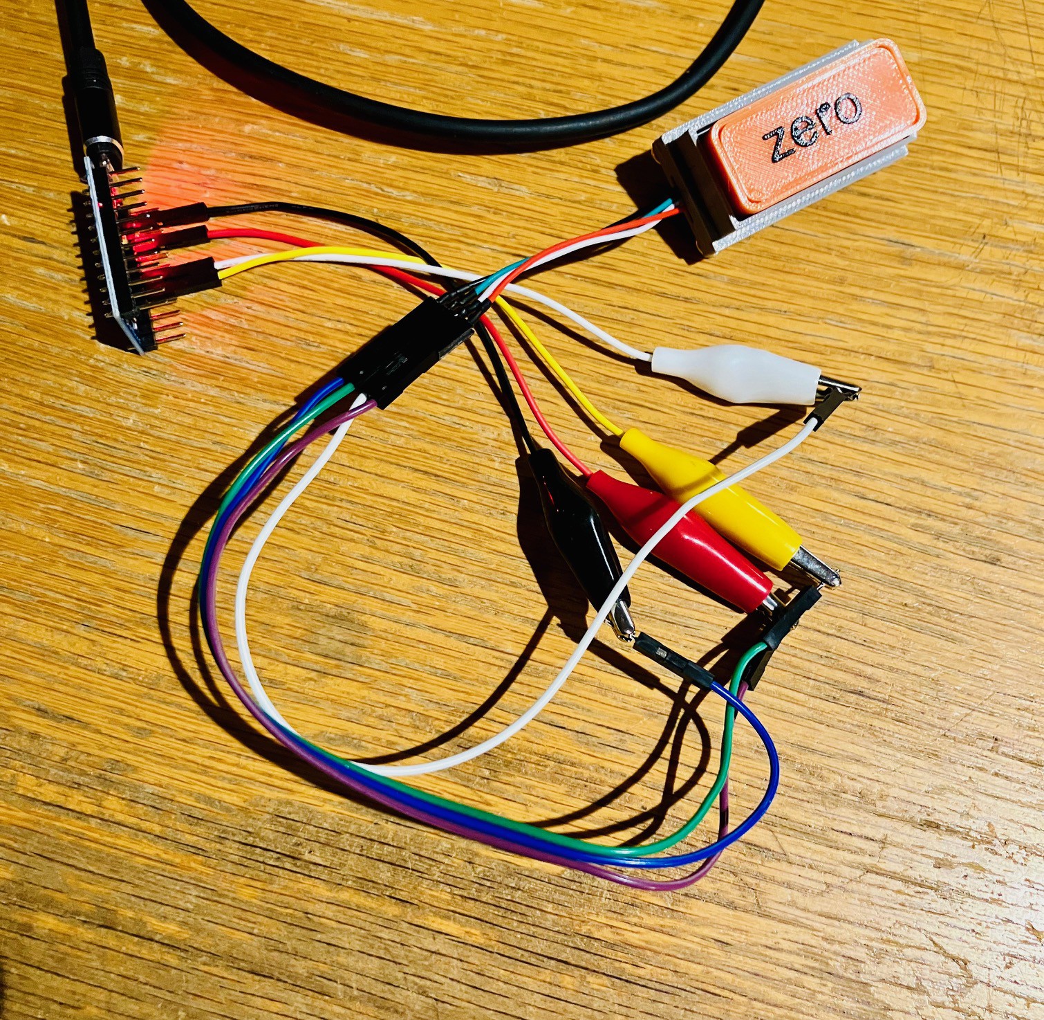
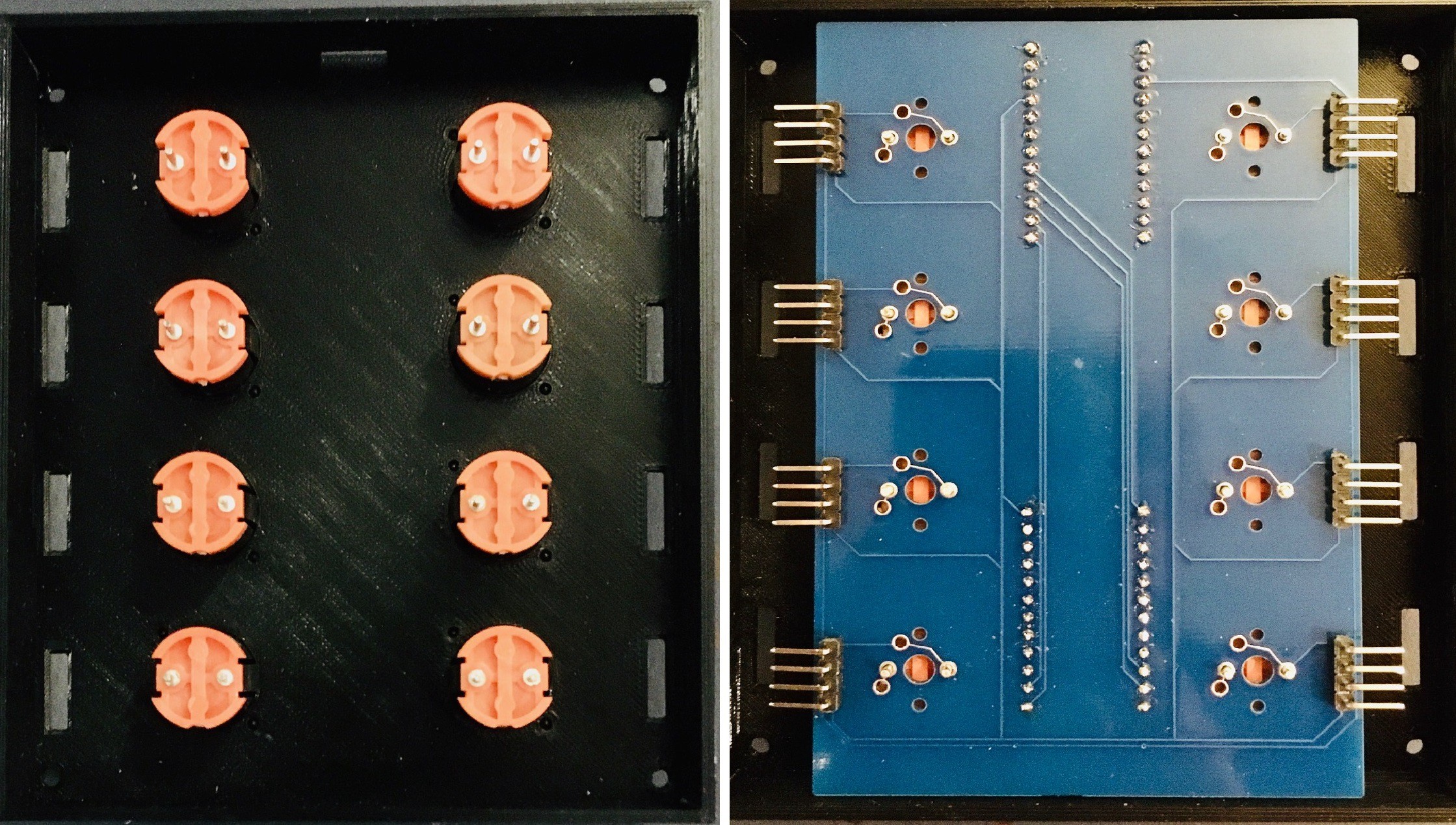
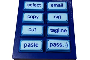
Outwardly this version of the MacroPad will not look any different than my last version (except for the new color scheme or should I say lack of color scheme). The inside will however be much cleaner than the rats nest of wires of the previous using the same components.

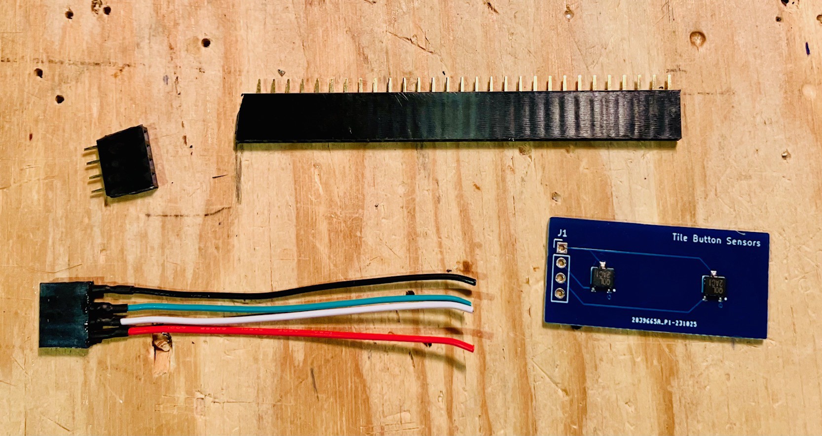
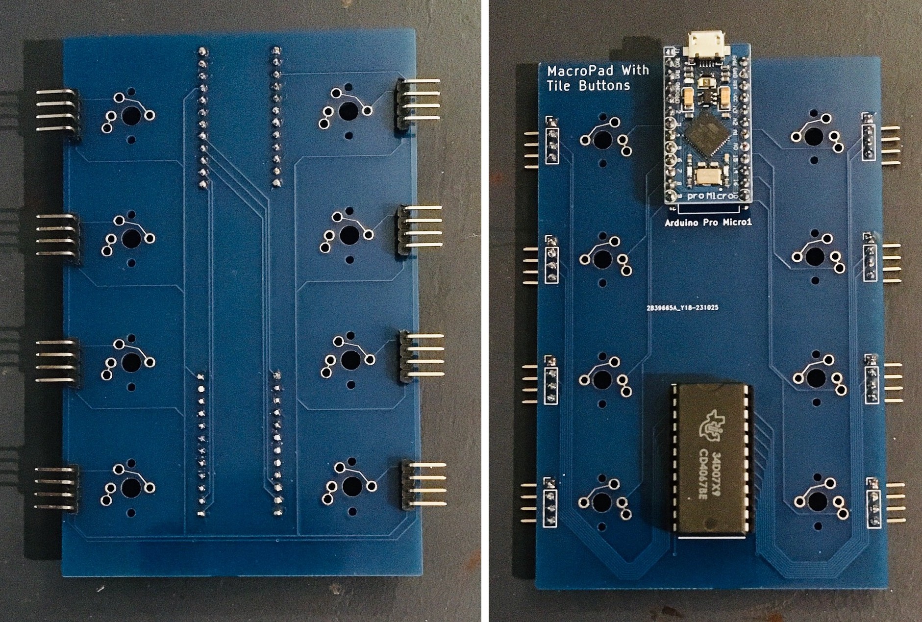
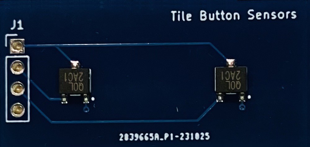
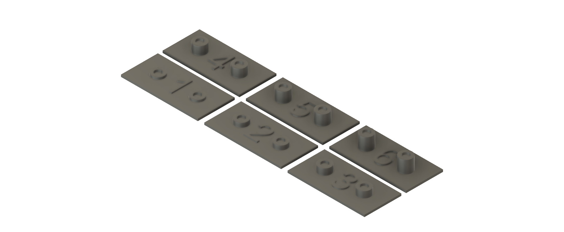
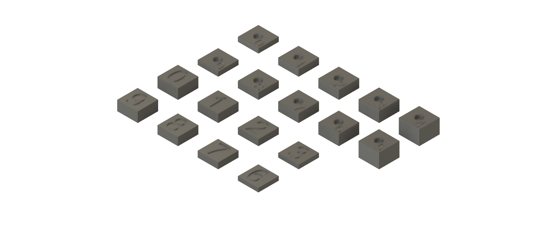
Here are the KiCad designs for the PCBs that will make this happen.

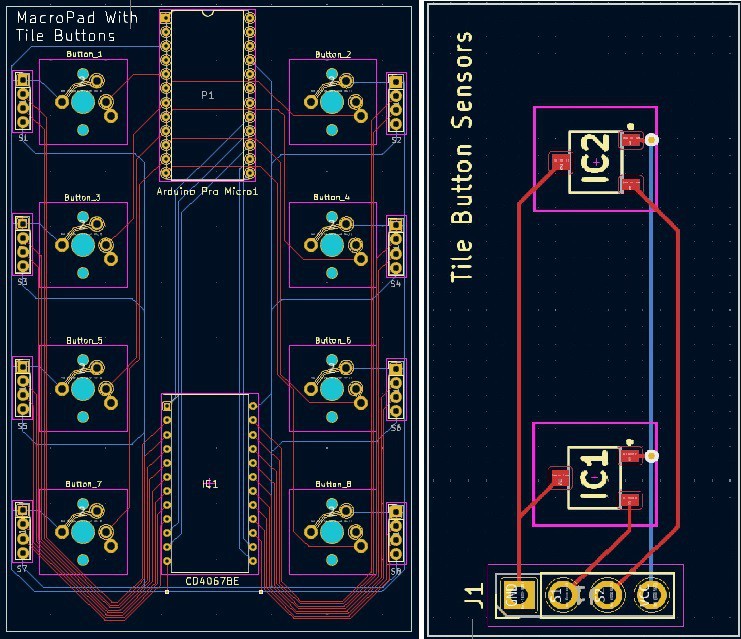
Obviously not to scale relative to each other but these PCBs give you an idea where I'm going with this.

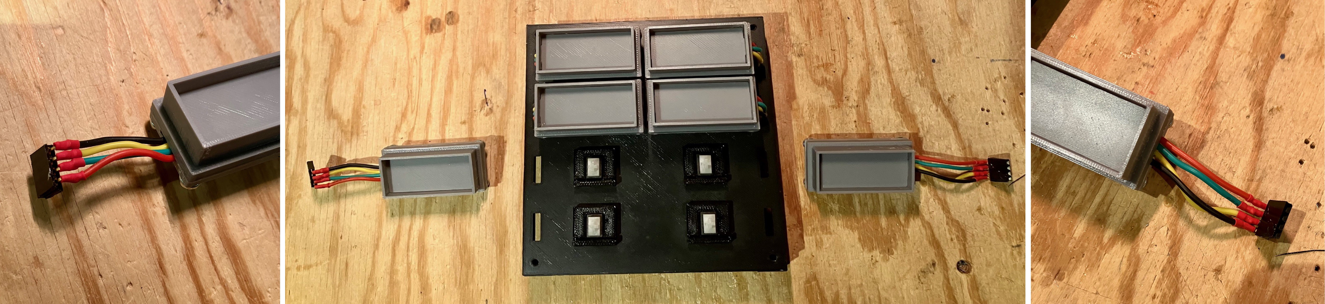
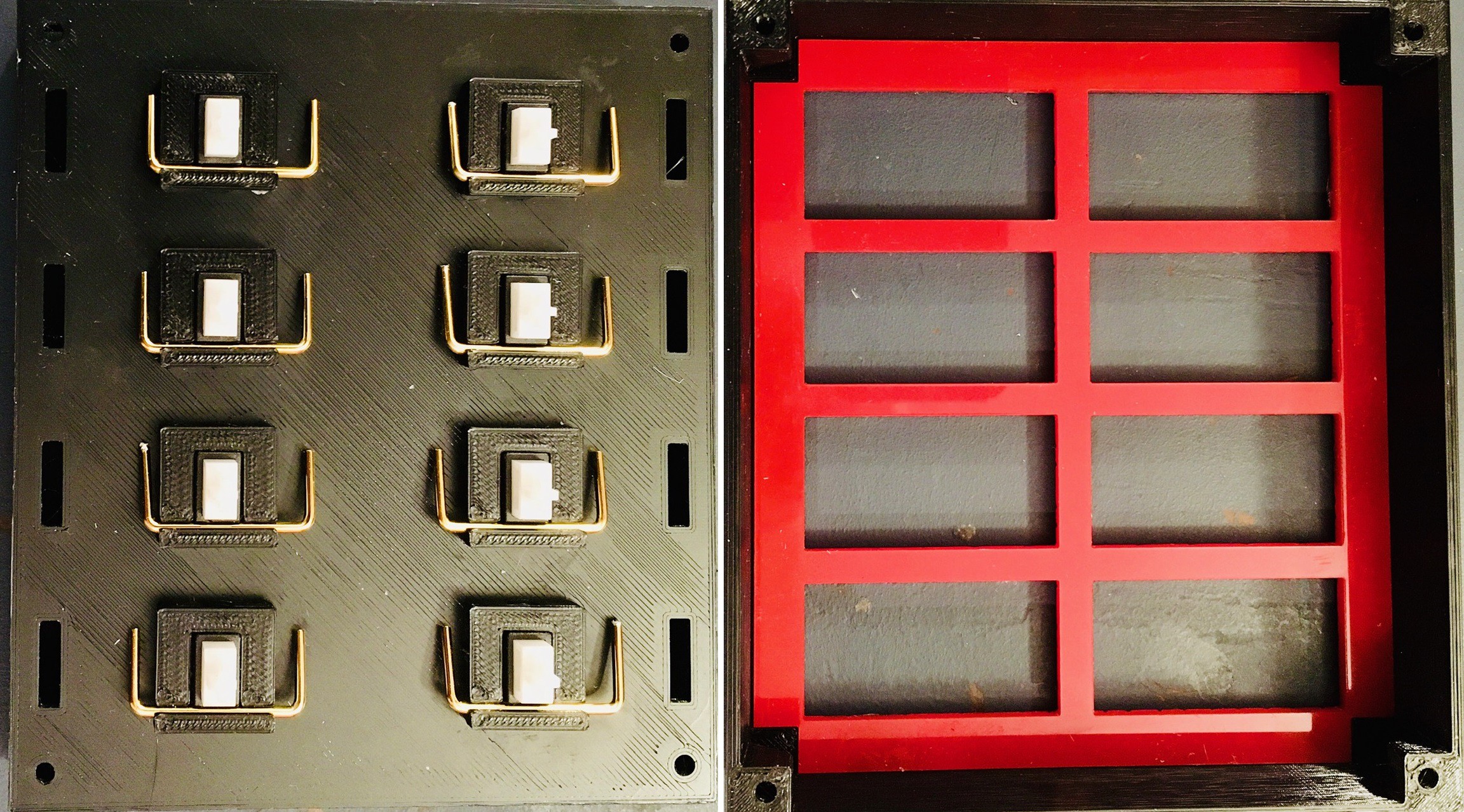
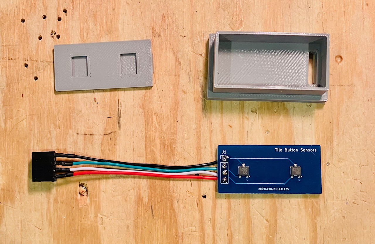
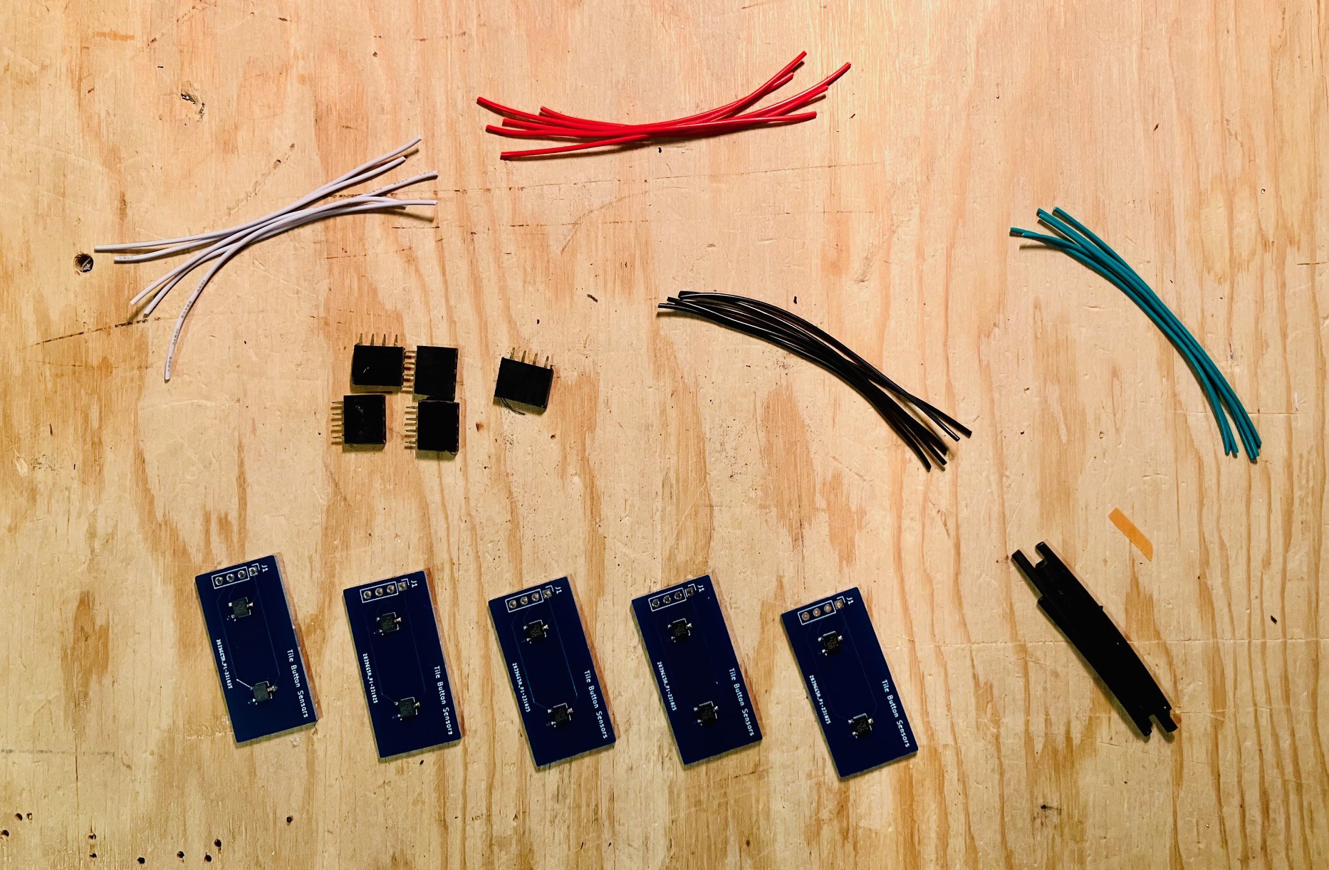
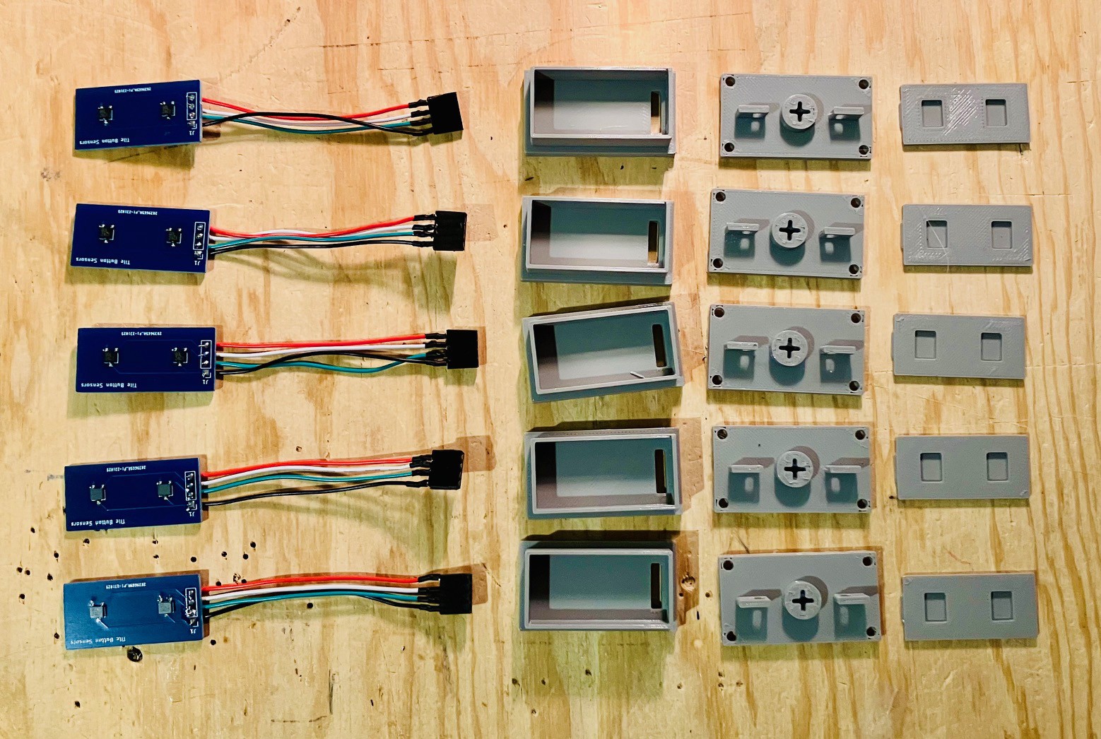
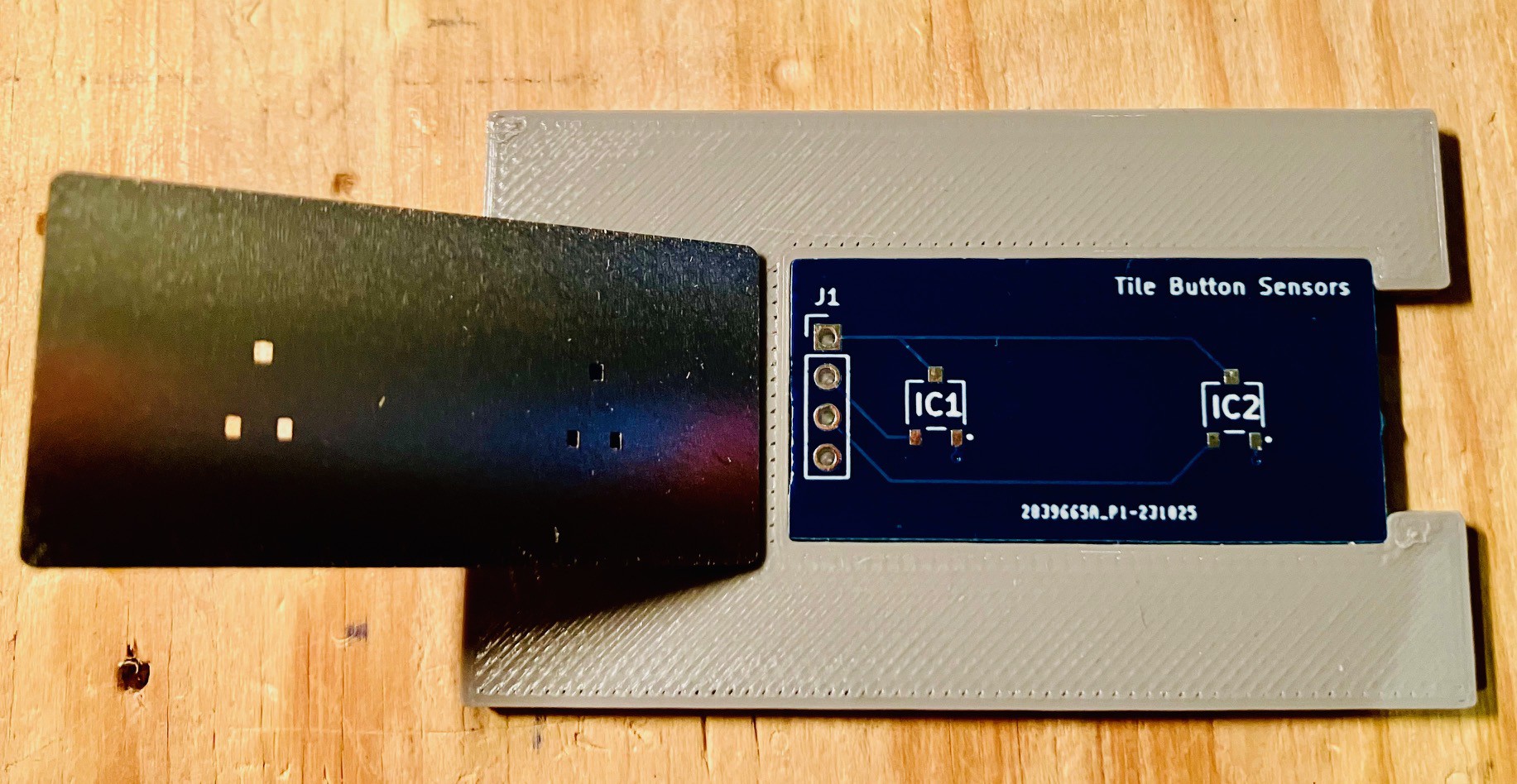
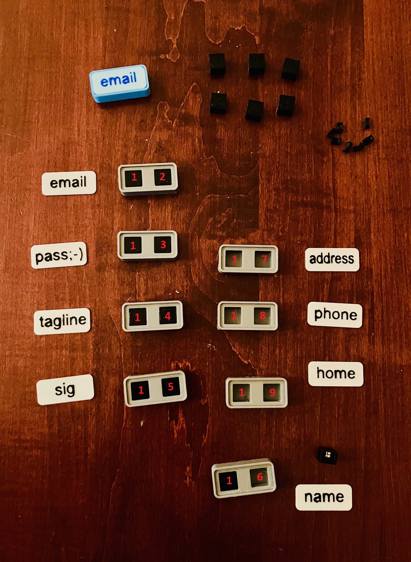
I now have the PBCs in hand and have printed all of the parts I need to make my new more robust MacroPad With Tile Holder Buttons.

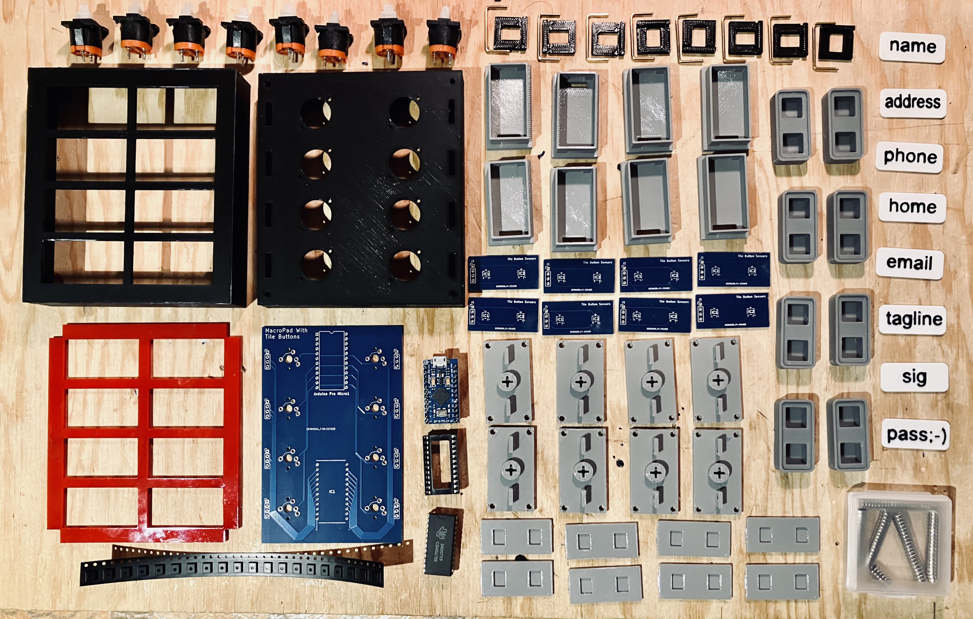
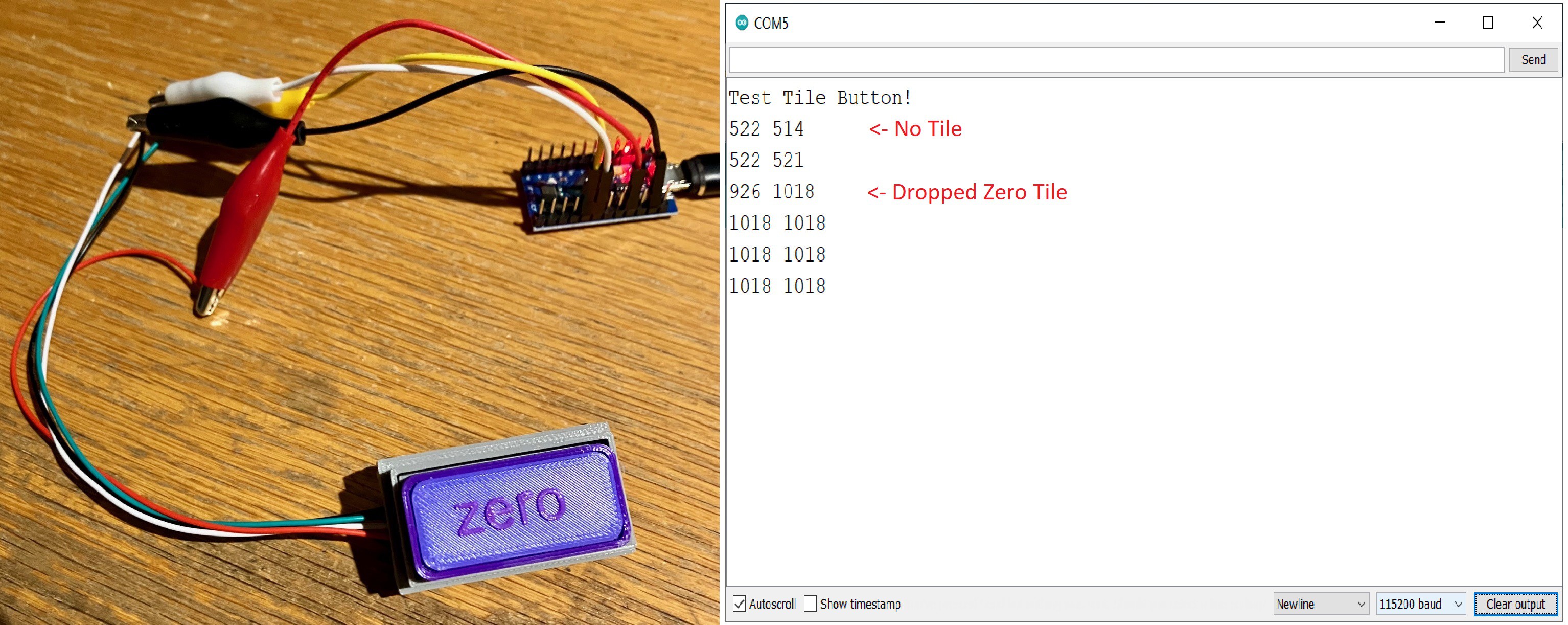
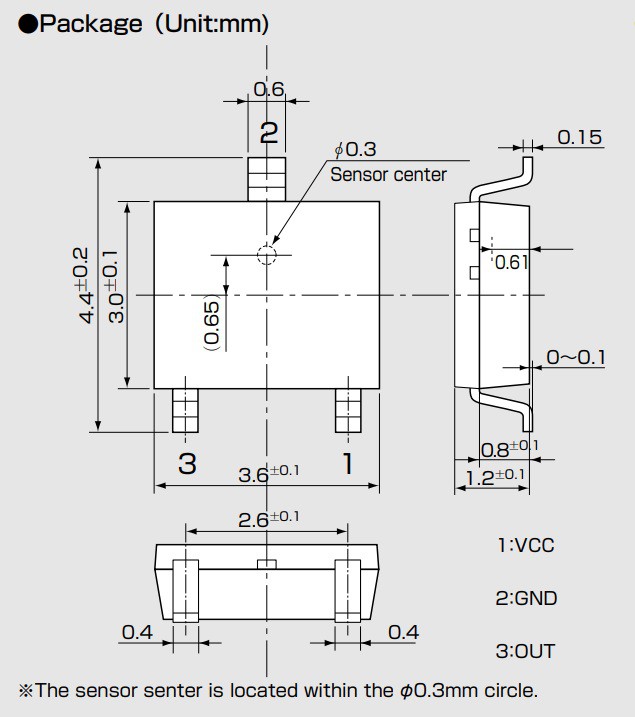
Before I start putting this all together I have to solder the SMD versions of the Hall effect sensors to the Tile Holder PCBs. I have never used SMD parts in a project so this will be a bit of a learning curve for me. Fortunately I am able to tap the expertise I need to get started from some of the great people at my local maker space Kwartzlab.
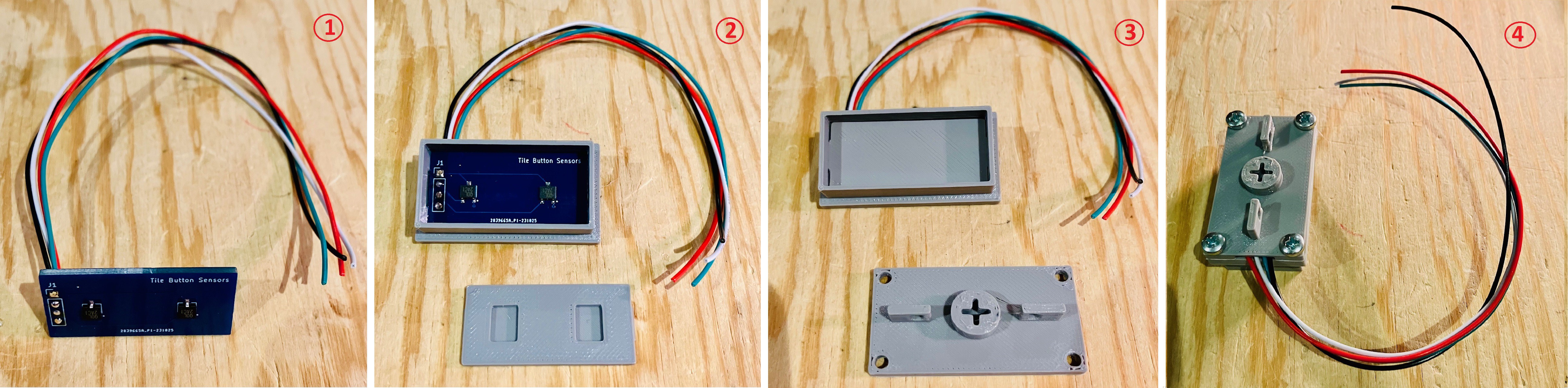
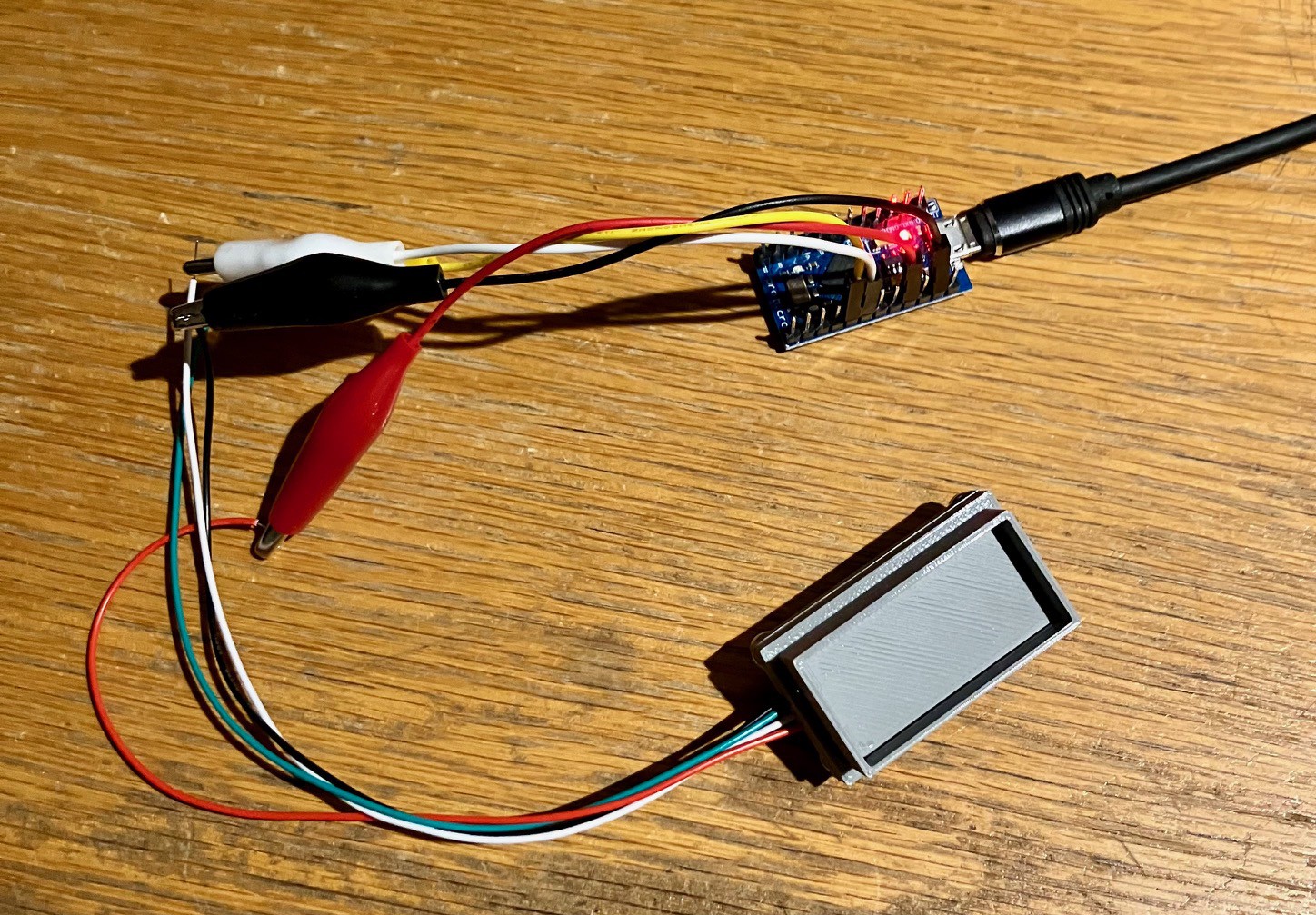
Montage

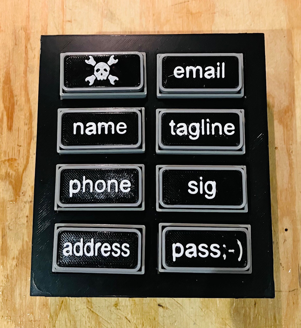
Picture a montage of me printing and soldering and building all at fast-forward speeds. At this point, given the background and design described above, I went ahead and finished my MacroPad 3. If you are interested in the details of how this happened I would strongly encourage you to have a look at this project's logs for the complete picture. Here is a handy link: Project Logs. Make sure that the SORT BY: is set to Oldest to get a chronological view.

Final Thoughts

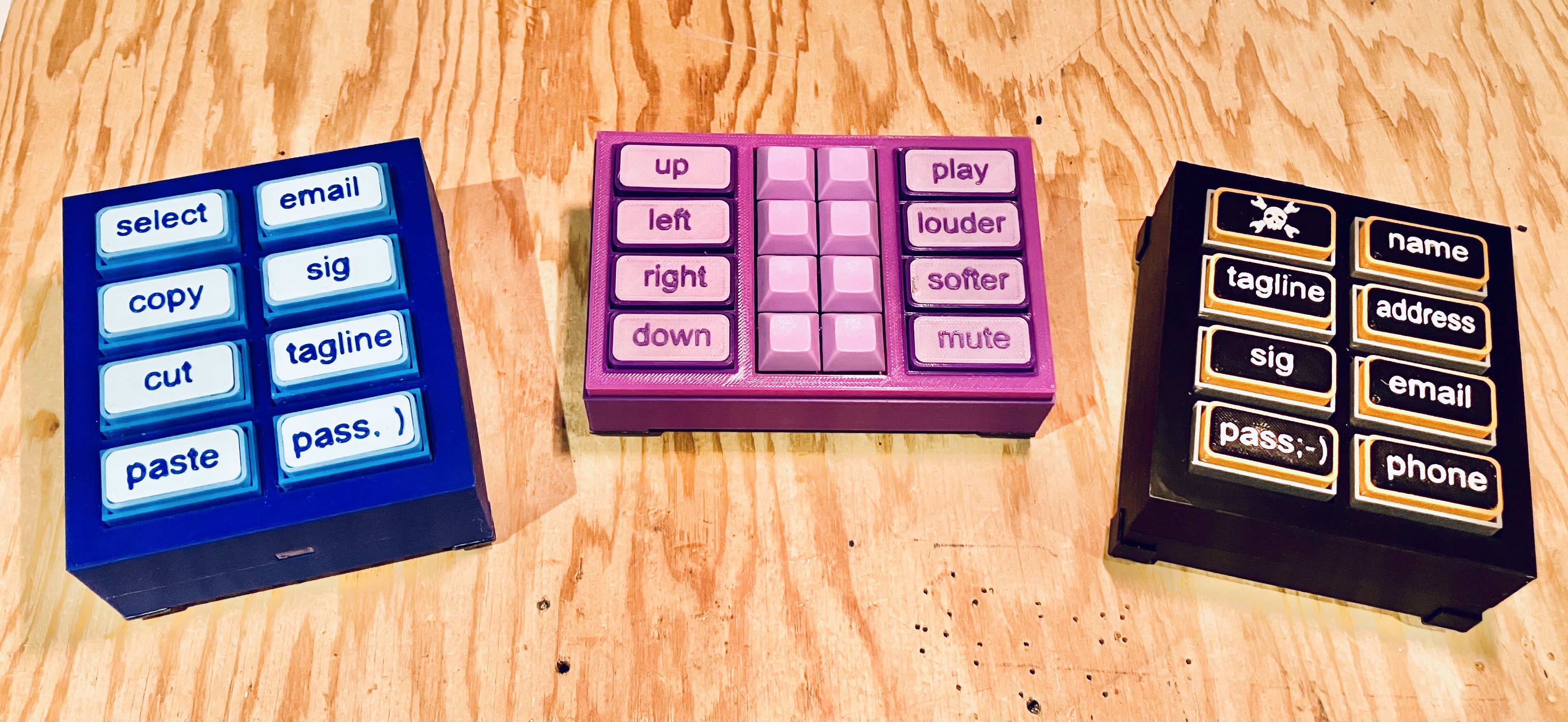
Well the last few months have been interesting.  Over that period of time I have created three similar tile based MacroPads. As each project wrapped up I kept thinking of improvements that I had to try. Fortunately for me, MacroPad 3 finally felt "done" but I'm not sure I'm completely done with tile based interfaces. We'll see I guess.

  • A Little Rework

    Michael Gardi12/17/2023 at 18:20 0 comments

    So the version I have at this point works just fine, but I was unhappy with how hard it was to attach the Tile Holder Buttons to the 4 pin headers on the PCB. Also the solid core wire that I was using was a little "stiff" and had a tendency to make the buttons tilt a bit. So I made a couple of small changes.  I switched to soft silicone stranded 28 AWG wire and 90 degree headers for connectors.

    For the most part the assembly is the same as described previously, but there is one thing to watch out for. 

    For switches going on the left side, the connector is installed facing down as in the left picture above. Right hand side button has the connector facing up, and the connector has to be rotated 180 degrees before attaching then to the PCB headers. The wires for for left hand side switches should be 42 mm long and for the right side 46 mm (to allow for the twist in the wires).

    Overall it was a bit of work, but totally worth ending up with a much cleaner build.

  • Color Scheme Tweak

    Michael Gardi11/23/2023 at 16:12 0 comments

    To be a true Hackaday themed design I needed to add dark yellow/orange to the palette. 

  • Final Assembly

    Michael Gardi11/18/2023 at 21:46 0 comments

    As with my previous MacroPad, I laser cut a piece of 3 mm acrylic (red) to fit into the top panel. This makes a big difference in reducing the grating feel/noise when pushing in a Tile Holder Button. Mount the laser cut button guide into the top piece of the MacroPad base with a little CA glue as pictured below.

    To the bottom part of the MacroPad base I glued in some caps that slide on top of the Fubata switches and hold the stabilizer wires in place for the buttons.

    Then I installed the Tile Holder Buttons. Push the wires down the slot beside the switch. It's a little tricky sliding the stabilizer wires into their holes as you press the button in place on top of the switch. I used a pair of tweezers to guide the wires and got better with each one.

    It's easiest if you work from back to front.

    When all of the Tile Holder Buttons are in place , flip the base and plug in the wire connectors. The black wires should be at the top.

    Then I attached the top of the base over the buttons with 4 M3 x 6 mm bolts and added some rubber feet.

    That's it. Ready for some tiles and testing.

  • Adding A Connector to the Tile Holder Button

    Michael Gardi11/17/2023 at 20:39 0 comments

    I'm using standard pitch female headers to make connectors for the tile buttons. I cut a longer header into 4 pin lengths. I found it easier to attach the wires to the header before attaching them to the button.

    Above you can see the header connector attached to four wires that are about 65 mm in length. I used some heat shrink tubing to prevent shorting and to further secure the connector.  Then solder the wires to the sensor PCB from below as pictured below. 

    Now assemble the tile holder button as described in the PCB Tile Holder Buttons log.

    Then a quick test.

    And on to the next. Time for some assembly line work.

    Imagine a fast forward video of me assembling these button holder sensor units.

    Again assemble the remaining five tile holder buttons as described in the PCB Tile Holder Buttons log.

  • Assemble The Base

    Michael Gardi11/17/2023 at 01:13 0 comments

    Compared to the dead bug wiring of the previous version, putting together this new MacroPad couldn't be easier. 

    1. First soldered in a 24 pin socket and install the CD4067BE 16-Channel Analog Multiplexer.
    2. Insert the pro Micro so that the legs of the header protrude from the bottom of the PCB about 1 mm.  Solder the pro Micro in place.
    3. Solder in the 4 pin 90 degree male headers as depicted below. (Note: my original plan was to have the 90 degree headers mounted the other way so they would be on the inside of the base. I changed my mind because I thought it would be too hard to plug in the wire plugs from the tile holders. Also I think there needed to be more "slack" between the tile holder an the PCB to allow the buttons to move freely. As a consequence the header now extends a few mm below the bottom of the base. For this version I will simply add some rubber feet to the base. I have increased the depth of the base on the 3D model so this will not be a problem for subsequent builds.)

    With the eight Fubata MD-4PCS switches inserted, carefully slide the PCB over the switch pins. Be patient and careful as it's a little tricky getting all of the pins to line up.

    At this point I did not solder the switch pins in place because I was not sure how hard it will be to plug in the wire harnesses from the tile holders later on.  

    NOTE: When you do solder the buttons to the PCB, make sure that the buttons are inserted flush with the base or else the switch could end up tilting a bit which causes them to scrape against the slots in the top of the base and possibly stick. Don't ask me how I know.

    Preparing the tile holders and adding the wire plugs is my next task.

  • A Hackaday Color Scheme

    Michael Gardi11/13/2023 at 18:13 0 comments

    Since I had to redo the tiles, as described in my previous log, I decided to change the color scheme a bit. This is a bit of an homage to Hackaday.

  • PCB Tile Holder Buttons and Whoops

    Michael Gardi11/12/2023 at 16:00 0 comments

    My SMD Experience

    My first experience using SMD parts went well.  After practicing on some tiny 0402 resistors, the hall effect sensor parts seemed absolutely gigantic. This board was basically a "Hello, World." for SMD fabrication. I probably could have hand soldered the parts (maybe) or applied the solder paste by hand, but I was looking for the full SMD experience. So I designed and printed a jig to hold the PCB.

    I had a stencil created along with the PCBs and used this rig to setup ten Tile Button Sensor panels. Then I used the reflow oven at Kwartzlab to finish the parts. A big thanks to Erin and Konstantin at Kwartzlab for their help getting me going on this.

    Tile Holder Button Assembly

    To make the PCB version of the Tile Holder Button:

    1. Solder four leads to the PCB header from the bottom as pictured above. The square via (pin 1) on the header is ground and the opposite side is power. The two middle pins are for the hall effect sensor outs.
    2. Slide the leads through the slot in the bottom of the Tile Holder Button Top. 
    3. Install the PCB Holder with the cutouts facing down. The tabs on the short side of the PCB holder should securely snap into the groves on the inside of the tile holder top. 
    4. Attach the Tile Holder Button Bottom with four M3 x 6 mm bolts making sure that the wires are routed through the wiring channel provided.

    Testing

    I still have a pro Micro setup to test Tile Buttons. I wired up the new Tile Holder Button.

    I ran my simple button testing Arduino sketch and dropped in one of my calibration tiles and: 

    "YES!" it works, quickly followed by "OH, that's a problem.".

    Whoops

    I really should have though this through a bit, especially before I created the new tiles that I wrote about in the previous log entry.  While I was careful to make sure that the EQ-430L SMD hall effect sensors were linear and bipolar like the SS49E through hole parts I was using, I paid no attention to the sensor sensitivity. It turns out that the SMD parts that I purchased are WAY more sensitive to magnetic fields than the through hole parts. This may have been exacerbated by my better aligning the sensor "sweet spot" with the center of the magnets for this new version of the tile button. 

    What does this mean? Well all of my existing tiles overpower the new sensor and return only 0 (GND) or 1018 (maxVCC) values if present depending on the polarity of the magnet. The neutral value with no magnets is still in the low 500s. How can this be fixed?

    Recalibrating the Tiles

    My existing tiles use two 6 mm x 1.8 mm cylindrical neodymium magnets per sensor. For the new sensor I had to go back to the drawing board to find magnets more suitable to increased sensitivity. I have quite a few cylindrical magnets of various sizes, so I started by manually holding them in turn above the new sensor, moving them closer and further away, while monitoring the values returned by the Test Tile Button! sketch. It wasn't until I got to my smallest magnet, 3 mm x 1.6 mm, that I found one that looked like it would work. 

    I did some further testing to verify these smaller magnets. I created some test tiles to hold these magnets at various distances from the sensors.

    The numbers on the tiles indicate the distance from the sensor (in mm).  Using these test tiles and the tile button holder just assembled I get the following values.

    Tile # / DistancePolarity ValueReverse Polarity Value
    1 mm 1018 - 10180 - 0
    2 mm895 - 877100 - 105
    3 mm750 - 729254 - 280
    4 mm642 - 636341 - 364
    5 mm562 - 588389 - 405
    6 mm549 - 569419 - 428

    These look pretty reasonable with a good separation between the readings based on distance. So the fix wasn't too bad. I just had to create a new set of magnet holders for the new magnets.

    Of course this means that tiles created for this version of the MacroPad will not be compatible with the previous versions, and that the tiles that I made...

    Read more »

  • Tiling

    Michael Gardi11/09/2023 at 18:27 0 comments

    While waiting to connect with my SMD mentors at Kwartzlab, I decided to make some new tiles utilizing the black-grey-white color scheme. This is fairly straight forward but you have to be careful with polarity and orientation

    In this image I am about half done. I am using an existing tile to determine the proper magnetic polarity for these new tiles. I have added in red numbers the values that I have assigned to the various macros (email = 12, pass ;-) = 13, etc.). 

    Polarity

    The Hall effect sensors I am using will return a different value depending on the polarity of a nearby magnet. The scheme that I am using when reading the sensor is to subtract the midpoint value (obtained by reading the sensor without a magnet present during calibration - pretty consistently around 525) from the current reading.  The magnet holders (labeled 0 to 4) that I am using are set at 5 different distances from the sensor, which results in potentially 10 distinct values 5 positive and 5 negative. 

    So I have assigned the positive values returned to the numbers 0, 1, 2, 3, and 4, same as the labels on the top of the magnet holders. With the magnets inserted into the holders with the reversed polarity the negative numbers returned are assigned the values 5, 6, 7, 8, and 9.  So for example the value assigned to the sig tile, 15,  is obtained by adding a magnet holder labeled 1 with magnets inserted with positive polarity, and a second magnet holder labeled 0 with magnets inserted with negative polarity.  With negative polarity 0=5, 1=6, 2=7, 3=8, and 4=9. Clear as mud right?

    Orientation

    You also have to be sure that the label is attached to the tile with the proper orientation. In the photo above the labels are oriented correctly for the tiles they are beside. Makes sense right, sig equals 15 not 51. 

    For the MacroPads I have made so far using SS49E sensors, it turns out even if the value of the tile were 11 say, flipping the tile (with the text upside down) would not work correctly. Something that I did not realize when I made my first two MacroPads is that the center point for the hall effect sensor is not the center of the packaging. A flipped tile will return different results because the center point of the sensor is not aligned with the center point of the circular magnets. Hopefully I have corrected this issue with this new PCB version.

    Update 17/12/2023

    I can verify that I got the sensors and magnets lined up correctly.  Tiles will read correctly regardless of orientation. That is to say that a tile that reads 1-2 will read 2-1 if rotated 180 degrees. Will not map to the expected macros, but does get the numeric values right.

View all 8 project logs

Enjoy this project?

Share

Discussions

Similar Projects

Does this project spark your interest?

Become a member to follow this project and never miss any updates