-
2Step 2
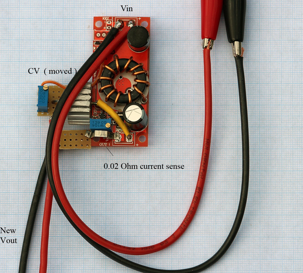
Initial modifications to step-down circuit
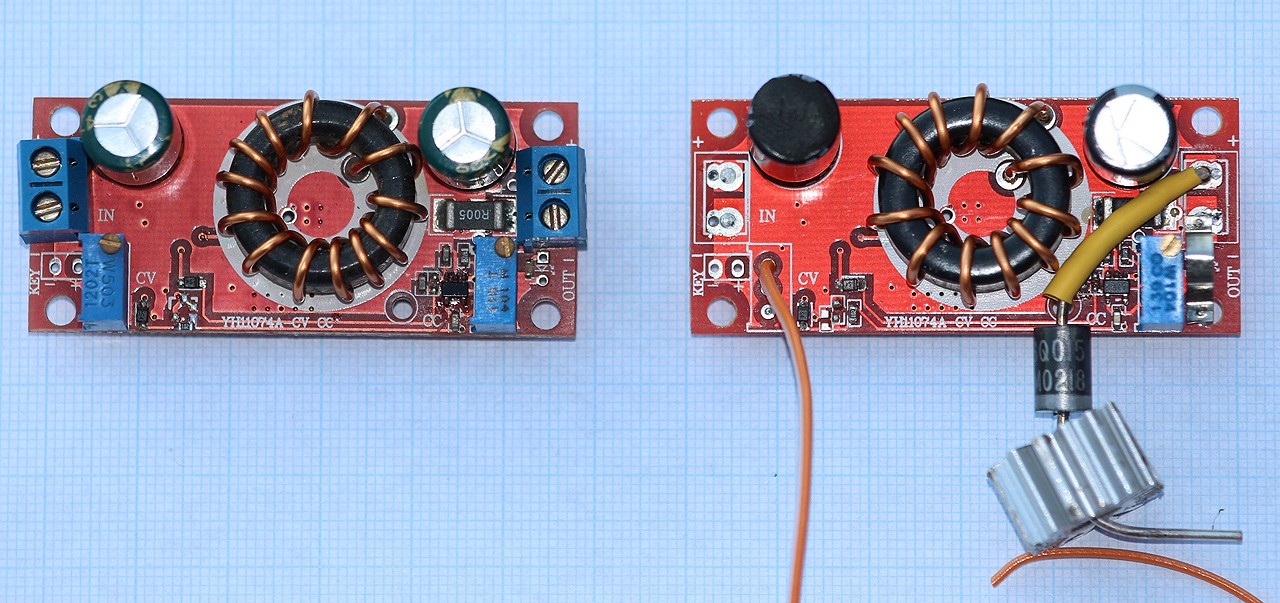
* Replace Sanyo capacitors with Rubycon 470µF ( optional )
* Solder reverse blocking diode to Vout+
* Desolder CV sense potentiometer and solder a wire ( orange )
* Solder 0.02 Ω current sense resistor to Vout-
-
3Step 3
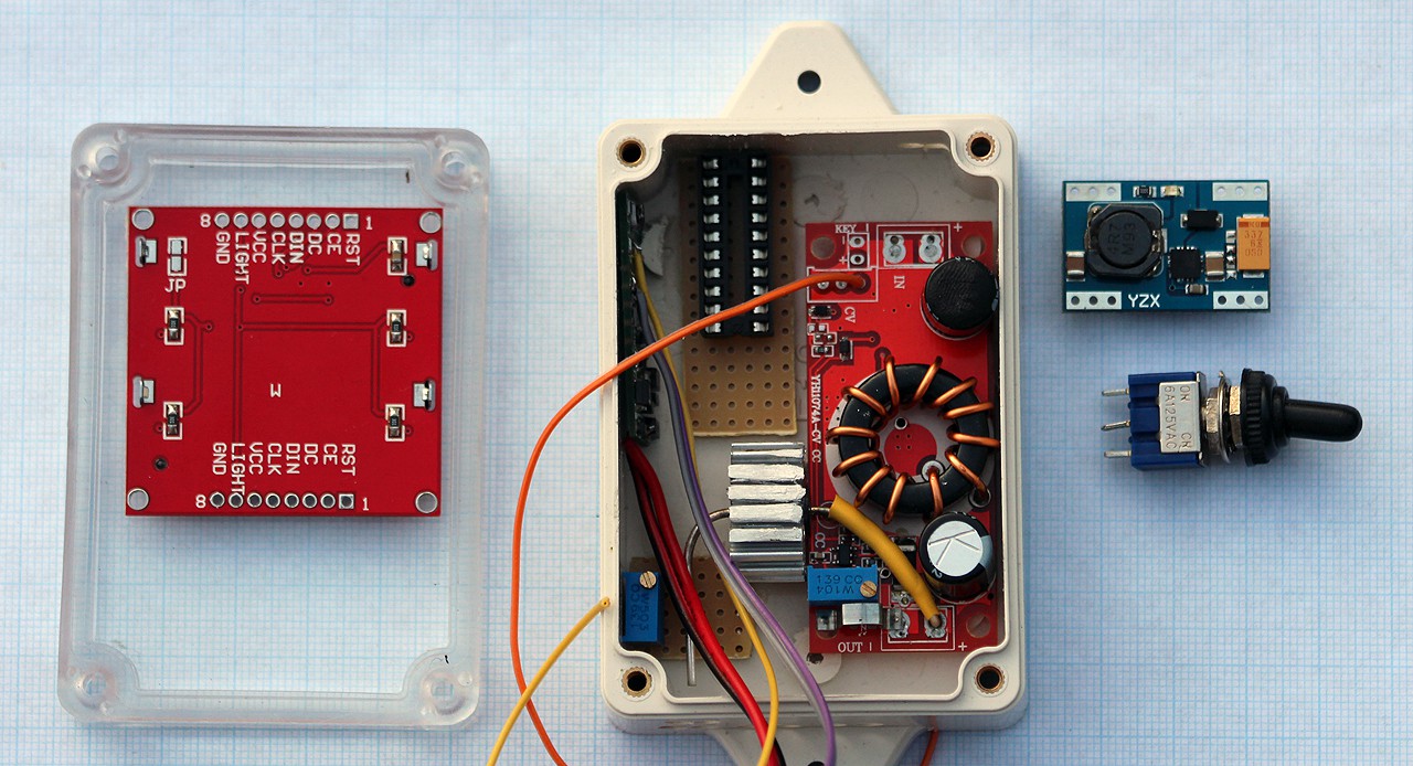
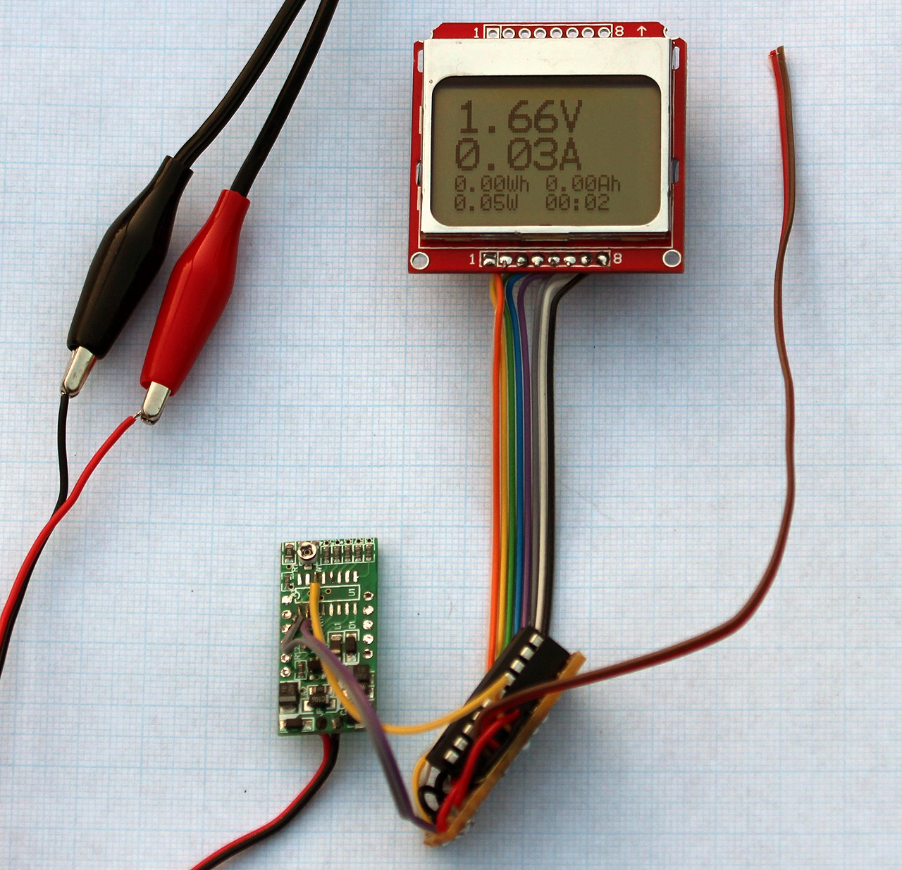
buck-boost (3.2)-3.3V from a gutted ebay voltmeter
( my guess is it's something similar to a Dickson Doubler with a 3.3V regulator )
* Desolder CPU
* Desolder LED ( 7-segment )
* Solder wire to regulated voltage 3.3 V ( purple )
* Solder wire to GND ( gray )
* Solder wire to voltage divider ( yellow )
* Apply voltage and verify you get 3.3V ( grey-purple) when you vary supply voltage 1.7-25V ( black-red ). Voltage sense( yellow) should vary accordingly if soldered correctly
-
4Step 4
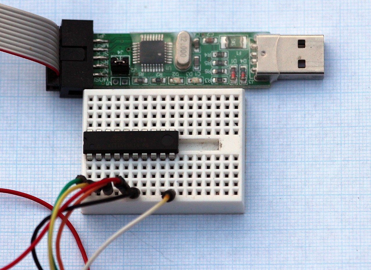
Flash ATtiny861
1. build software 1charger_src ver 0.95 with WinAvr and Code::Blocks
Read this for basic ATtiny development ....
cd C:\1Charger\src
make clean
make2. Flash
avrdude -p t861 -c usbasp -u -Uflash:w:1CHG.hex:a -Ueeprom:w:1CHG.eep:a
pre bulit with CALIBRATION
avrdude -p t861 -c usbasp -u -Uflash:w:1CHG-CALIB.hex:a -Ueeprom:w:1CHG.eep:a -
6Step 6
-
7Step 7
-
8Step 8
Complete modifications to step-down converter ( from step 2 )
* Solder 50k Ω CV resistor ( moved )
* Solder new Vout ( from reverse blocking diode )
* Solder silicone wires to Vin
* Solder silicone wires to the new Vout
* Apply voltage to Vin and verify that the new Vout can be controlled with the 50k Ω CV potentiometer
* Adjust new Vout to 3.55V for LiFePO4 single cell
-
9Step 9
There can be only one
Complete the 1Charger by soldering the two circuits together ( from step 7,8 )
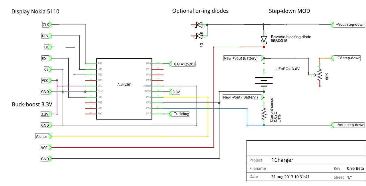
Solder current sense to ATtiny861
* new -Vout to PA5 ( pin13)
* old -Vout to PA6 ( pin12)
Solder 3.3V buck-boost supply to new Vout
* Vcc+ to new +Vout ( from Schottky diode )
* GND to new -VoutTest outside the box, calibrate and test everything before inserting it int the project box.
-
10Step 10
Calibrate connected-ish ( serial port )
The serial port is useful for making charge curves and debug. I use a usb to serial cable that accept 3.3v level.Connect the serial cable to GND and pin PA7
The software UART timer interrupt is also used as a timebase. If you care about serial output this calibration should be completed before time calibration. You probably have to adjust TX_TIMERVALUE =12 (default). The timer prescale is 8. Theoretically the timervalue = F_CPU/(baudrate*prescale) = 1E6/(9600*8)=13. By changing this value between 11-14 you will probably get it right ( recompile flash, test with Tera Term )
 mr.jb
mr.jb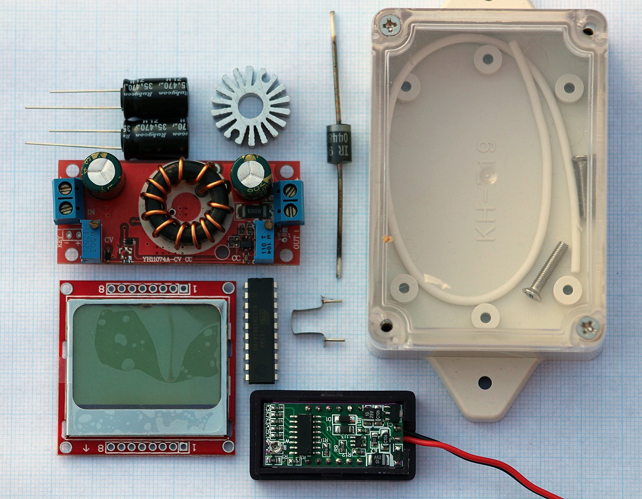

Discussions
Become a Hackaday.io Member
Create an account to leave a comment. Already have an account? Log In.