The ESP32 is a commonly used wifi and Bluetooth enabled microcontroller which nicely demonstrates the usefulness of MetaShunt as a measurement and debugging tool. When connected to WiFi and operating at full speed, the ESP32 can consume a lot of power (some sources report up to 240mA maximum). However, it also has low power modes that can get the current consumption down to about 5uA, a level 48,000 times lower than its maximum! MetaShunt is the perfect tool for analyzing the power of such a system. A multimeter is incapable of keeping up with the rapid changes in power consumption, and multiple ranges would likely be needed. A simple current shunt monitored by an oscilloscope would suffer from resolution issues - a shunt sized for 240mA will not be useful at 5uA, and a shunt sized for 5uA will not work at 240mA (the system would brown out). MetaShunt can easily measure current across these ranges without browning out the system.
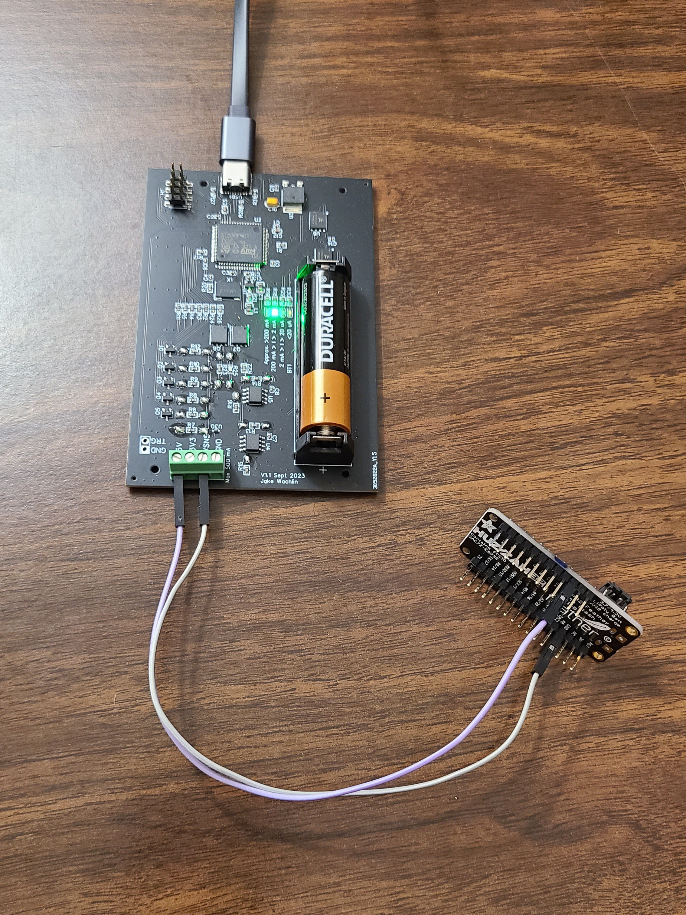
This test was completed with an ESP32 Huzzah development board from Adafruit, since it is what I had on-hand. This is not the ideal board to test low-power consumption with, because it has a UART to USB adapter component and a battery charger on board, neither of which can be put into low power mode. Nonetheless, the microcontroller portion of it can be controlled to enter and exit low power modes, as well as connect to WiFi, and I will demonstrate monitoring this system using MetaShunt.
The board was connected to MetaShunt by the 5V and VSNS pins, just like in the prior log. Note that the measurements will therefore also include quiescent current from the voltage regulator.
The following Arduino sketch was used in this test. Various active busy waits, waits while connected to WiFi, online data queries, and low power modes are demonstrated. Care is taken before entering deep sleep to turn on the RTC for wakeup later and to set all GPIO into the best power saving mode (this is really important for getting the last few uA out of a low power system).
#include <WiFi.h>
#include "time.h"
#include "driver/rtc_io.h"
#include "driver/gpio.h"
#include "esp_wifi.h"
#include "driver/adc.h"

//#define USE_SERIAL      1

RTC_DATA_ATTR int bootCount = 0;

const char* ssid       = "MYSSID";
const char* password   = "MYPASSWORD";

const char* ntpServer = "pool.ntp.org";
const long  gmtOffset_sec = 3600;
const int   daylightOffset_sec = 3600;


void printLocalTime()
{
  struct tm timeinfo;
  if(!getLocalTime(&timeinfo)){
    Serial.println("Failed to obtain time");
    return;
  }
  Serial.println(&timeinfo, "%A, %B %d %Y %H:%M:%S");
}

void setup() {
  #ifdef USE_SERIAL
  Serial.begin(115200);
  #endif

  pinMode(13,OUTPUT);
  delay(500);

  digitalWrite(13,HIGH);

  delay(2500);

  digitalWrite(13,LOW);

  //connect to WiFi
  #ifdef USE_SERIAL
  Serial.printf("Connecting to %s ", ssid);
  #endif
  WiFi.begin(ssid, password);
  while (WiFi.status() != WL_CONNECTED) {
      delay(15);
      #ifdef USE_SERIAL
      Serial.print(".");
      #endif
  }
  #ifdef USE_SERIAL
  Serial.println(" CONNECTED");
  #endif

  //init and get the time
  configTime(gmtOffset_sec, daylightOffset_sec, ntpServer);
  delay(200);
  int i;
  for(i = 0; i < 10; i++)
  {
    digitalWrite(13,!digitalRead(13));
    delay(100);
  }
  digitalWrite(13,LOW);

  #ifdef USE_SERIAL
  printLocalTime();
  #endif

  //disconnect WiFi as it's no longer needed
  WiFi.disconnect(true);
  WiFi.mode(WIFI_OFF);

  esp_sleep_enable_timer_wakeup(3000000); // 3 sec
  esp_light_sleep_start();
  // we'll wake from light sleep here

  //Set things up for lower power
  // ESP32 docs say to isolate pin 12 in deep sleep to save power
  rtc_gpio_isolate(GPIO_NUM_12);

  // Isolate other pins
  rtc_gpio_isolate(GPIO_NUM_39);
  rtc_gpio_isolate(GPIO_NUM_36);
  rtc_gpio_isolate(GPIO_NUM_35);
  rtc_gpio_isolate(GPIO_NUM_34);
  rtc_gpio_isolate(GPIO_NUM_32);
  rtc_gpio_isolate(GPIO_NUM_33);
  rtc_gpio_isolate(GPIO_NUM_27);
  rtc_gpio_isolate(GPIO_NUM_26);
  rtc_gpio_isolate(GPIO_NUM_25);
  rtc_gpio_isolate(GPIO_NUM_23);
  rtc_gpio_isolate(GPIO_NUM_22);
  rtc_gpio_isolate(GPIO_NUM_21);
  rtc_gpio_isolate(GPIO_NUM_19);
  rtc_gpio_isolate(GPIO_NUM_18);
  rtc_gpio_isolate(GPIO_NUM_17);
  rtc_gpio_isolate(GPIO_NUM_16);
  rtc_gpio_isolate(GPIO_NUM_15);
  rtc_gpio_isolate(GPIO_NUM_14);
  rtc_gpio_isolate(GPIO_NUM_13);
  rtc_gpio_isolate(GPIO_NUM_5);
  rtc_gpio_isolate(GPIO_NUM_4);
  rtc_gpio_isolate(GPIO_NUM_2);
  rtc_gpio_isolate(GPIO_NUM_0);

  esp_wifi_stop();
  adc_power_off();

  // hold GPIOs
  gpio_deep_sleep_hold_en();

  // wake up 1 second later and then go into deep sleep
  esp_sleep_enable_timer_wakeup(4000000); // 4 sec

  // Use auto mode to turn off only if not needed by wakeup mode
  esp_sleep_pd_config(ESP_PD_DOMAIN_RTC_SLOW_MEM, ESP_PD_OPTION_AUTO);
  esp_sleep_pd_config(ESP_PD_DOMAIN_RTC_FAST_MEM, ESP_PD_OPTION_AUTO);
  esp_sleep_pd_config(ESP_PD_DOMAIN_RTC_PERIPH, ESP_PD_OPTION_AUTO);

  esp_deep_sleep_start();

}

void loop() {

}
Measurements were then taken of this system. We can see in the image below that the power varies widely. This system is more complicated than the previous example, in large part because the ESP32 has two cores, and the networking core software is not shown here.
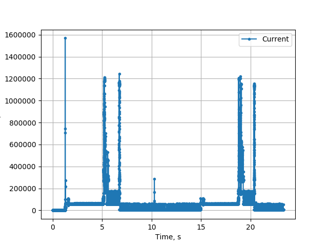
Let's look at each section of code and match it to the data! First, the LED pin is set high for 2.5 seconds and then turned off.
#ifdef USE_SERIAL
  Serial.begin(115200);
  #endif

  pinMode(13,OUTPUT);
  delay(500);

  digitalWrite(13,HIGH);

  delay(2500);

  digitalWrite(13,LOW);
We can see an initial section with slightly lower current, and then it jumps up slightly to about 60.6mA during the busy wait with LED on.

The WiFi is then connected, current time is pulled from the internet, and the LED is toggled 10 times over 1 second.
//connect to WiFi
  #ifdef USE_SERIAL
  Serial.printf("Connecting to %s ", ssid);
  #endif
  WiFi.begin(ssid, password);
  while (WiFi.status() != WL_CONNECTED) {
      delay(15);
      #ifdef USE_SERIAL
      Serial.print(".");
      #endif
  }
  #ifdef USE_SERIAL
  Serial.println(" CONNECTED");
  #endif

  //init and get the time
  configTime(gmtOffset_sec, daylightOffset_sec, ntpServer);
  delay(200);
  int i;
  for(i = 0; i < 10; i++)
  {
    digitalWrite(13,!digitalRead(13));
    delay(100);
  }
  digitalWrite(13,LOW);

  #ifdef USE_SERIAL
  printLocalTime();
  #endif
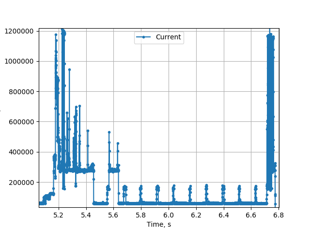
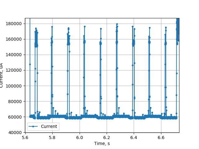
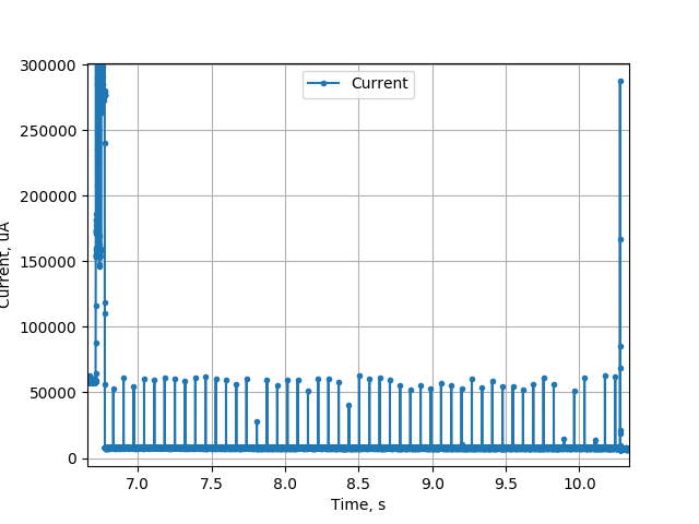
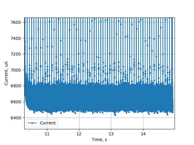
At the start, when connecting, the current jumps up very high, above 1A. It then drops down to roughly stable around 275mA. We see a second spike which presumably is when the time is queried from the internet. The current then drops lower and we see periodic spikes. These spikes seem to be from the WiFi stack - the ESP32 is periodically maintaining its connection, likely matching to the DTIM interval. When zoomed in on the second image below, the base current can be seen to increase and decrease as the LED is toggled.
Next, the WiFi is turned off and light sleep is used.
  //disconnect WiFi as it's no longer needed
  WiFi.disconnect(true);
  WiFi.mode(WIFI_OFF);

  esp_sleep_enable_timer_wakeup(3000000); // 3 sec
  esp_light_sleep_start();
  // we'll wake from light sleep here
We can see the current drop to around 7.7mA, with spikes up to approximately 60mA at about 14Hz. It is not clear what is causing that.

Finally, the ESP32 goes into deep sleep mode. Before we enter that mode, we set the pins into an efficient state.
  //Set things up for lower power
  // ESP32 docs say to isolate pin 12 in deep sleep to save power
  rtc_gpio_isolate(GPIO_NUM_12);

  // Isolate other pins
  rtc_gpio_isolate(GPIO_NUM_39);
  rtc_gpio_isolate(GPIO_NUM_36);
  rtc_gpio_isolate(GPIO_NUM_35);
  rtc_gpio_isolate(GPIO_NUM_34);
  rtc_gpio_isolate(GPIO_NUM_32);
  rtc_gpio_isolate(GPIO_NUM_33);
  rtc_gpio_isolate(GPIO_NUM_27);
  rtc_gpio_isolate(GPIO_NUM_26);
  rtc_gpio_isolate(GPIO_NUM_25);
  rtc_gpio_isolate(GPIO_NUM_23);
  rtc_gpio_isolate(GPIO_NUM_22);
  rtc_gpio_isolate(GPIO_NUM_21);
  rtc_gpio_isolate(GPIO_NUM_19);
  rtc_gpio_isolate(GPIO_NUM_18);
  rtc_gpio_isolate(GPIO_NUM_17);
  rtc_gpio_isolate(GPIO_NUM_16);
  rtc_gpio_isolate(GPIO_NUM_15);
  rtc_gpio_isolate(GPIO_NUM_14);
  rtc_gpio_isolate(GPIO_NUM_13);
  rtc_gpio_isolate(GPIO_NUM_5);
  rtc_gpio_isolate(GPIO_NUM_4);
  rtc_gpio_isolate(GPIO_NUM_2);
  rtc_gpio_isolate(GPIO_NUM_0);

  esp_wifi_stop();
  adc_power_off();

  // hold GPIOs
  gpio_deep_sleep_hold_en();

  // wake up 1 second later and then go into deep sleep
  esp_sleep_enable_timer_wakeup(4000000); // 4 sec

  // Use auto mode to turn off only if not needed by wakeup mode
  esp_sleep_pd_config(ESP_PD_DOMAIN_RTC_SLOW_MEM, ESP_PD_OPTION_AUTO);
  esp_sleep_pd_config(ESP_PD_DOMAIN_RTC_FAST_MEM, ESP_PD_OPTION_AUTO);
  esp_sleep_pd_config(ESP_PD_DOMAIN_RTC_PERIPH, ESP_PD_OPTION_AUTO);

  esp_deep_sleep_start();
The current at this point drops down to approximately 6.7mA. This is much higher than the hoped-for 5uA. It appears to be due to the UART-USB converter component which is powered on at all times on this development board. Here, we still see the periodic spikes in current as well.

Discussions
Become a Hackaday.io Member
Create an account to leave a comment. Already have an account? Log In.