 JP Gleyzes
The story
I have an old Trotec laser engraver which is almost totally dead:
- laser tube is almost blind
- software is using Windows95 OS
So more than 25 years later it was time to refurbish this machine.
- Changing the laser tube will be described into another project
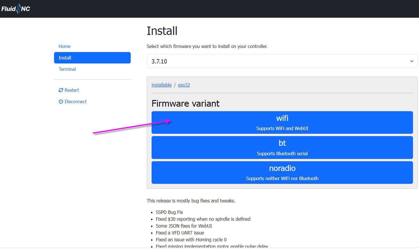
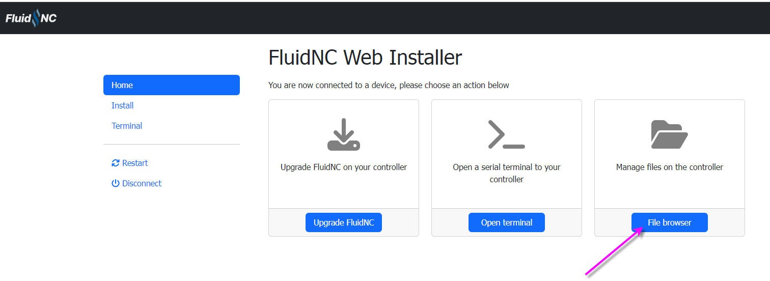
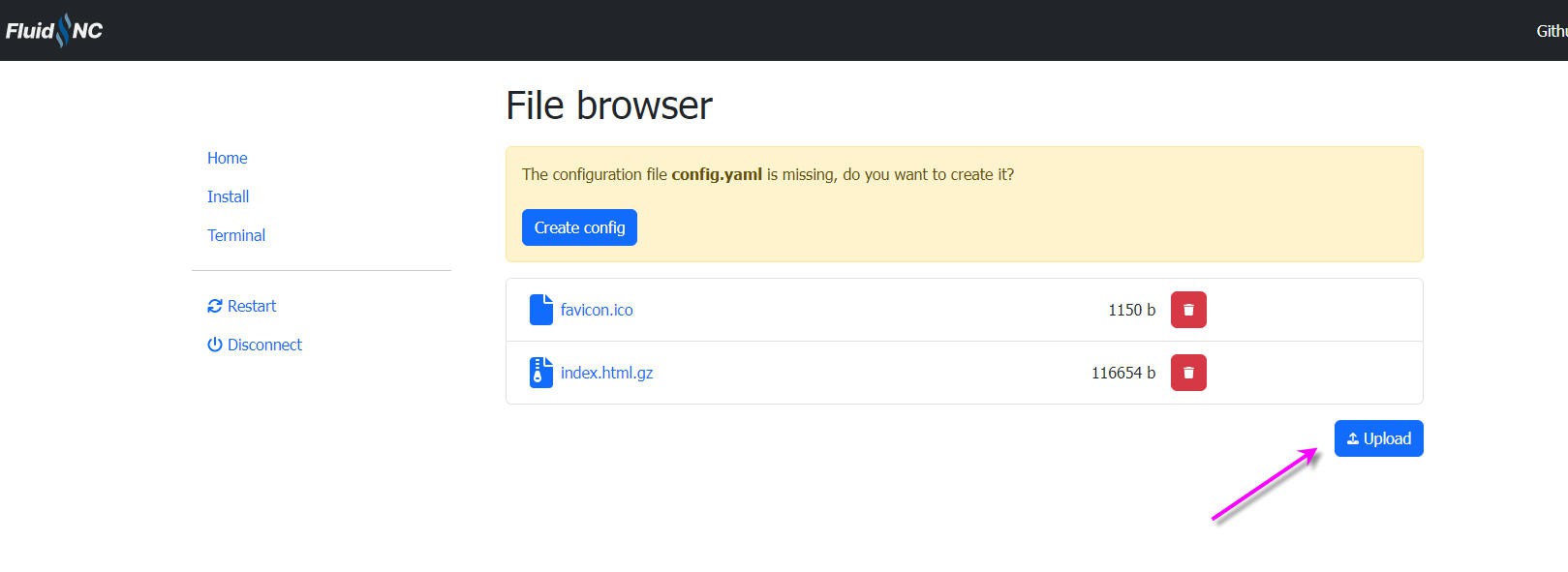
- Changing the control board should be simple...FluidNC can drive any stepper board
So I opened the machine and very soon discovered that steppers motors were not "steppers" but DC motors with encoders... and a very specific electronics to drive them...
Here is the rotary axis of this Trotec machine when "opened"
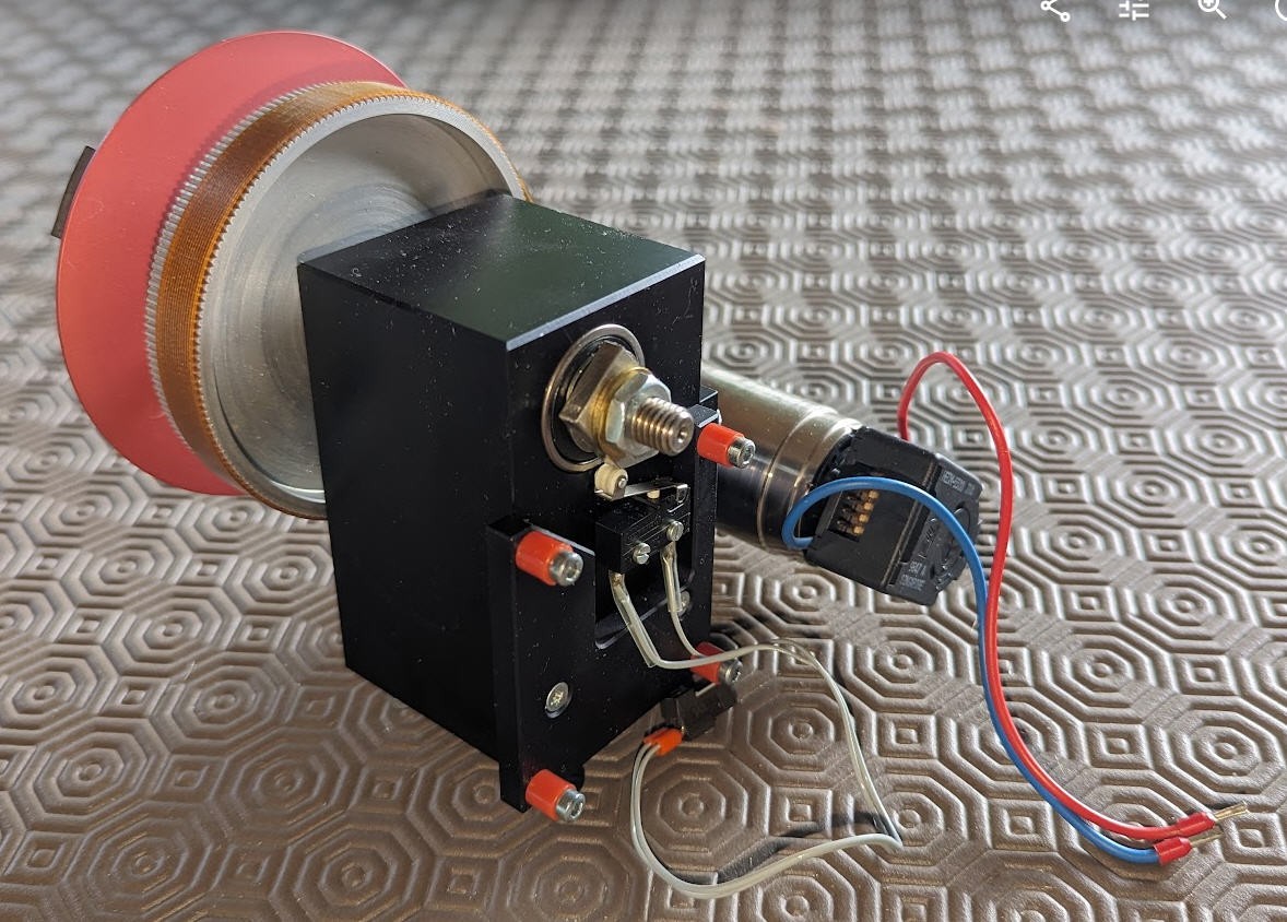
- on the right the DC motor
- on the end shaft of this motor is an optical encoder
- under the main shaft is a "home switch"
We will see how to reuse these elements to convert this motor into a stepper.
This mod will be demonstrated with this motor but will be generic enough to be applied on any other DC motor.
Main specifications are synthetised into this log
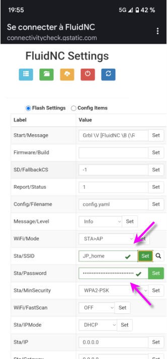
But let's start by a video showing the "final" product !
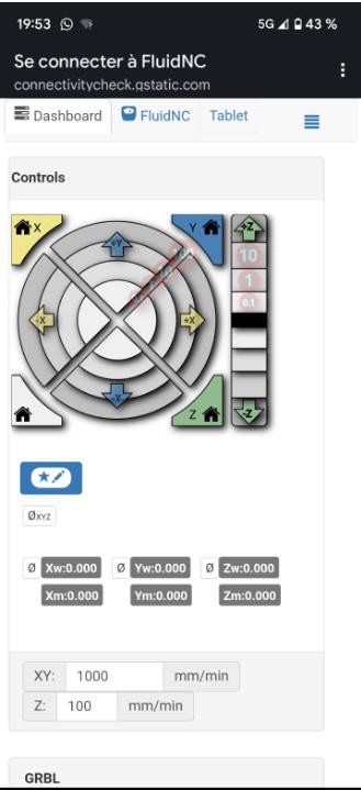
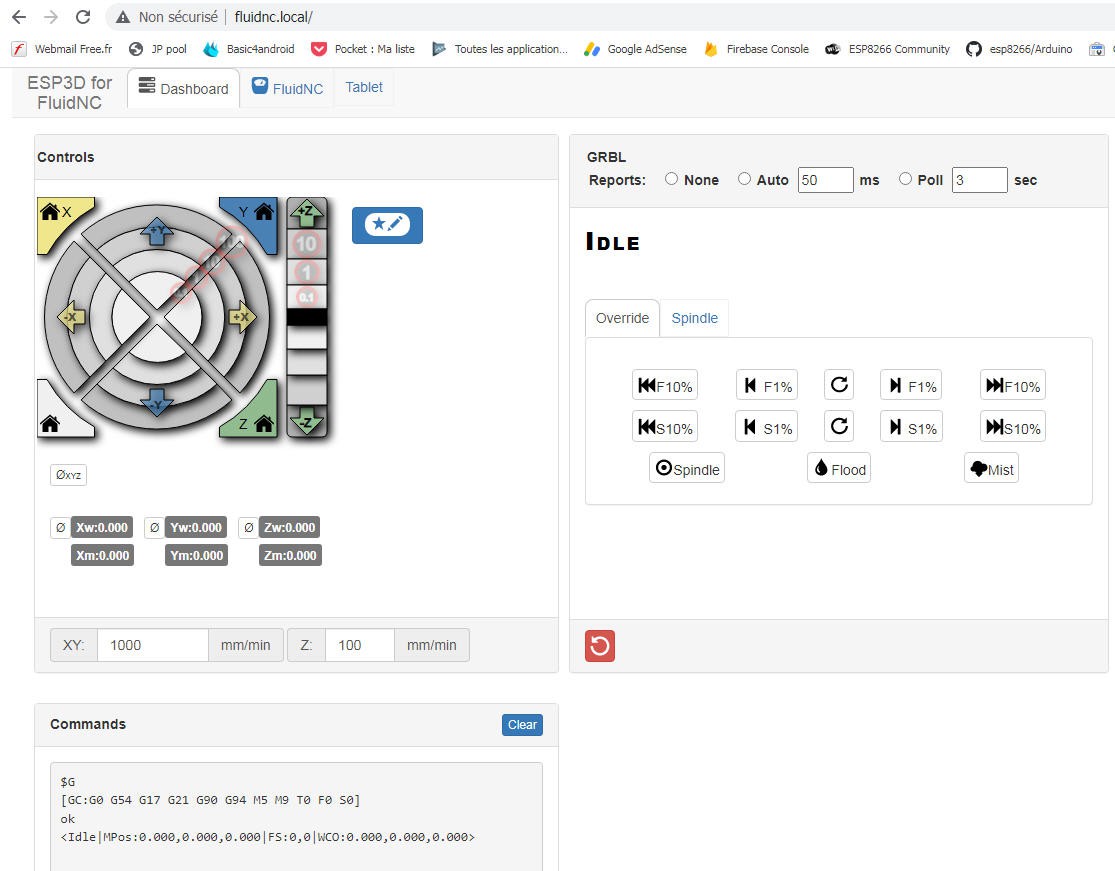
And a second one with this stepper (almost) installed into my Trotec laser. Control is still done by FluiNC and jogging done by gSender.
Before going further i must say that this controller will NOT act exactly as a stepper does.
I did mount two of these "pseudo steppers" into my CNC machine and added a pen plotter. Here is the result of what should have been a straight line at 45° in theXY plane (line x=y in cartesian coordinates)
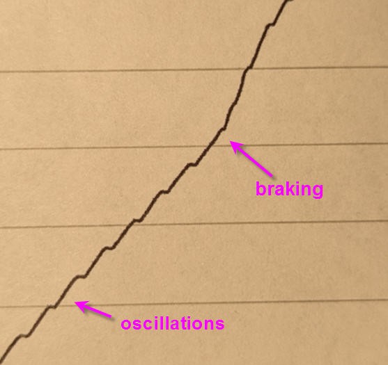
As you can see, oscilations are visible and the slope of the curve is not constant, we can clearly see when the braking is applied on one motor.
Consequently this controller is NOT suitable to precisely control a CNC. Despite the fact that the target position will be reached precisely, the motion itself is not linearly controlled. It is not a speed controlled PID. Furthermore the tuning of the PID will depend on the motor and two pieces (even from the same manufacturer) will not have exactly the same tuning...
This project is usefull to control position (number of steps) but not to control the speed to reach this position.
The DC motor driver
My motors are all 35NT2R_82_426SP ones. They are still manufactured by Portecap and have the following specs :
- 102 W,
- 32 V, --> power supply 24V
- 115 mNm,
- 5900 rpm,
- 3mm Shaft Diameter
To drive them I needed a driver able to sustain 24V and 4A
I chose the "IBT-2" one available on Aliexpress at very cheap price
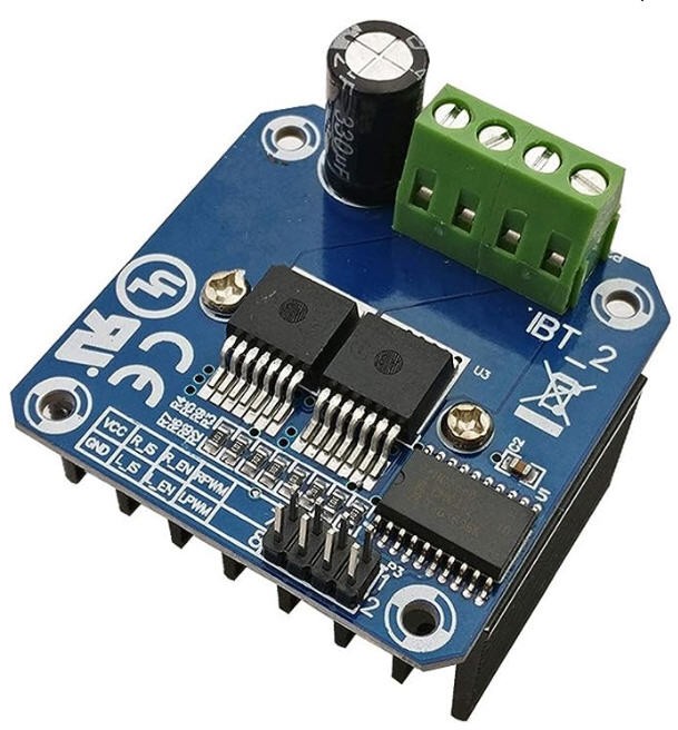
They are all equiped with a BTS7960 43A chip which is a dual H bridge with following specs:
- Input Voltage: 6 ~ 27Vdc.
- Dual BTS7960 H Bridge Configuration.
- Peak current: 43-Amp.
- PWM capability of up to 25 kHz.
- Control Input Level: 3.3~5V.
- Control Mode: PWM or level
- Working Duty Cycle: 0 ~100%.
- Over-voltage Lock Out.
- Under-voltage Shut Down.
So this driver is perfect for my setup. It can even be controlled by 5V or 3.3V logic MCU. An ESP32 will be perfect.
The encoder
Attached to the motor shaft is an optical encoder hedm-5500_J14 manufactured by Avago
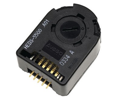
it has a Two channel quadrature output with a resolution of 1024 counts per revolution. It will be perfect to know precisely the shaft position.
Schematics
Here is the schematics of the driver board.
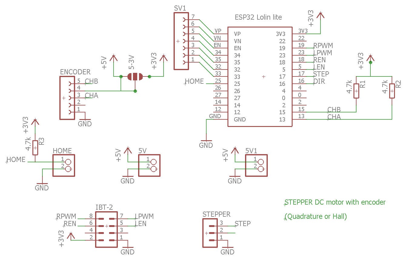
The heart of the system is a Lolin32 lite ESP32 board. And that's almost it !
You will find
- the encoder interface (5V or 3.3V if yours is more modern than mine)
- the Step/Dir connector
- input for the Home switch
Note that the encoder outputs need to be pulled up (CHA, CHB signals)
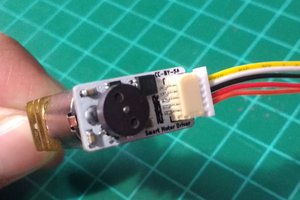
PCB
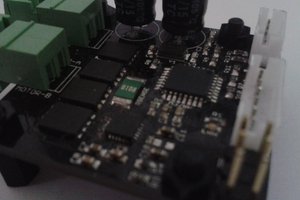
This schematics was routed into a tiny PCB which was kindly sponsored by PCBWay.
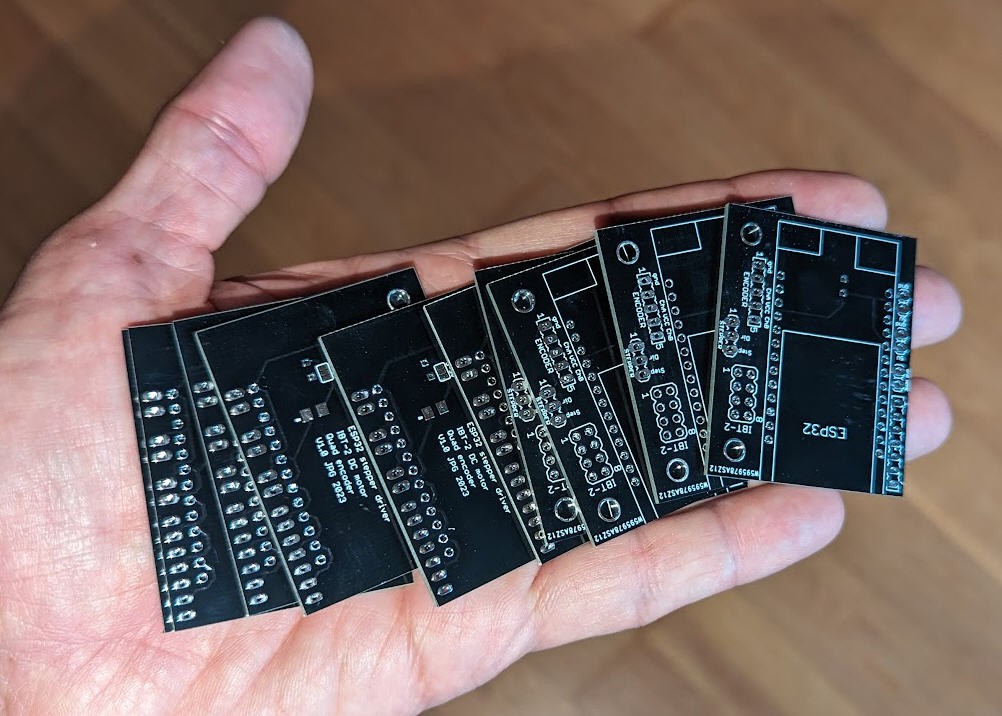
You can find it on PCBWay shared projects
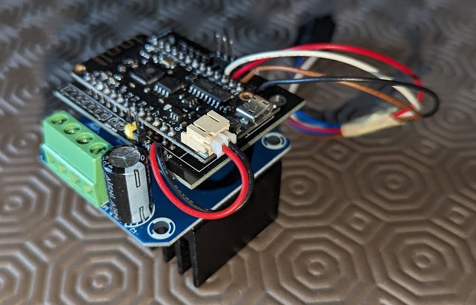
Soldering this board is as simple as it could be. The result is a "mezzanine" board to put and screw on top of the DC motor IBT-2 driver.
And here is the result into a small video :
Software
Software of this project is quite simple but rather "tricky".
We need...
Read more »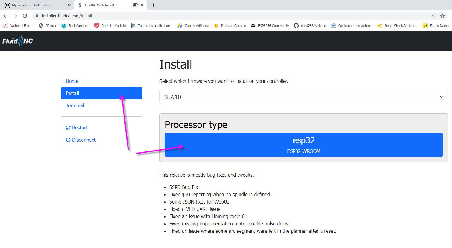

 ottoragam
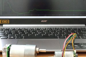
 Danny FR
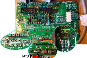
 James Newton
what is the cost for this project ?