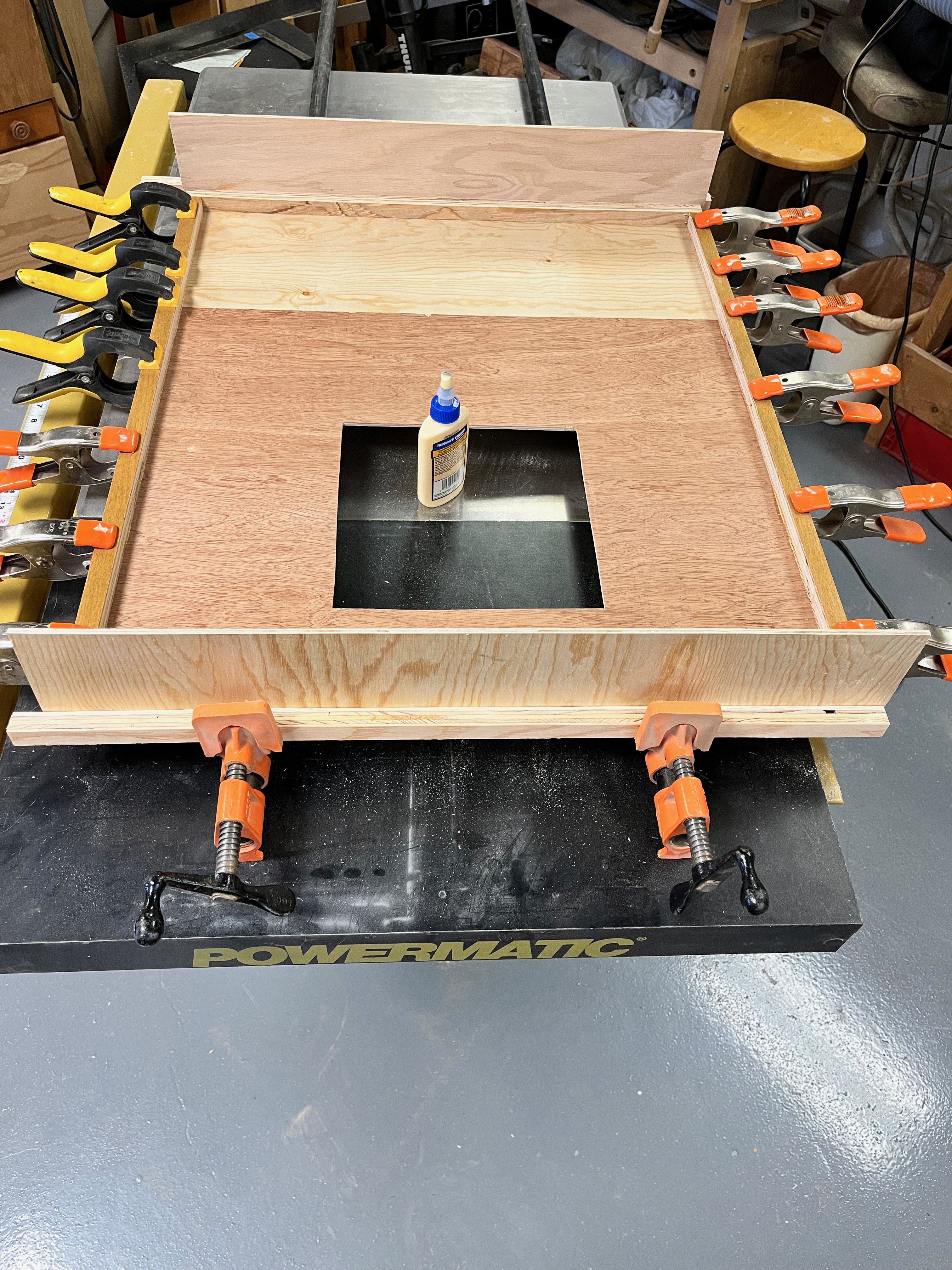
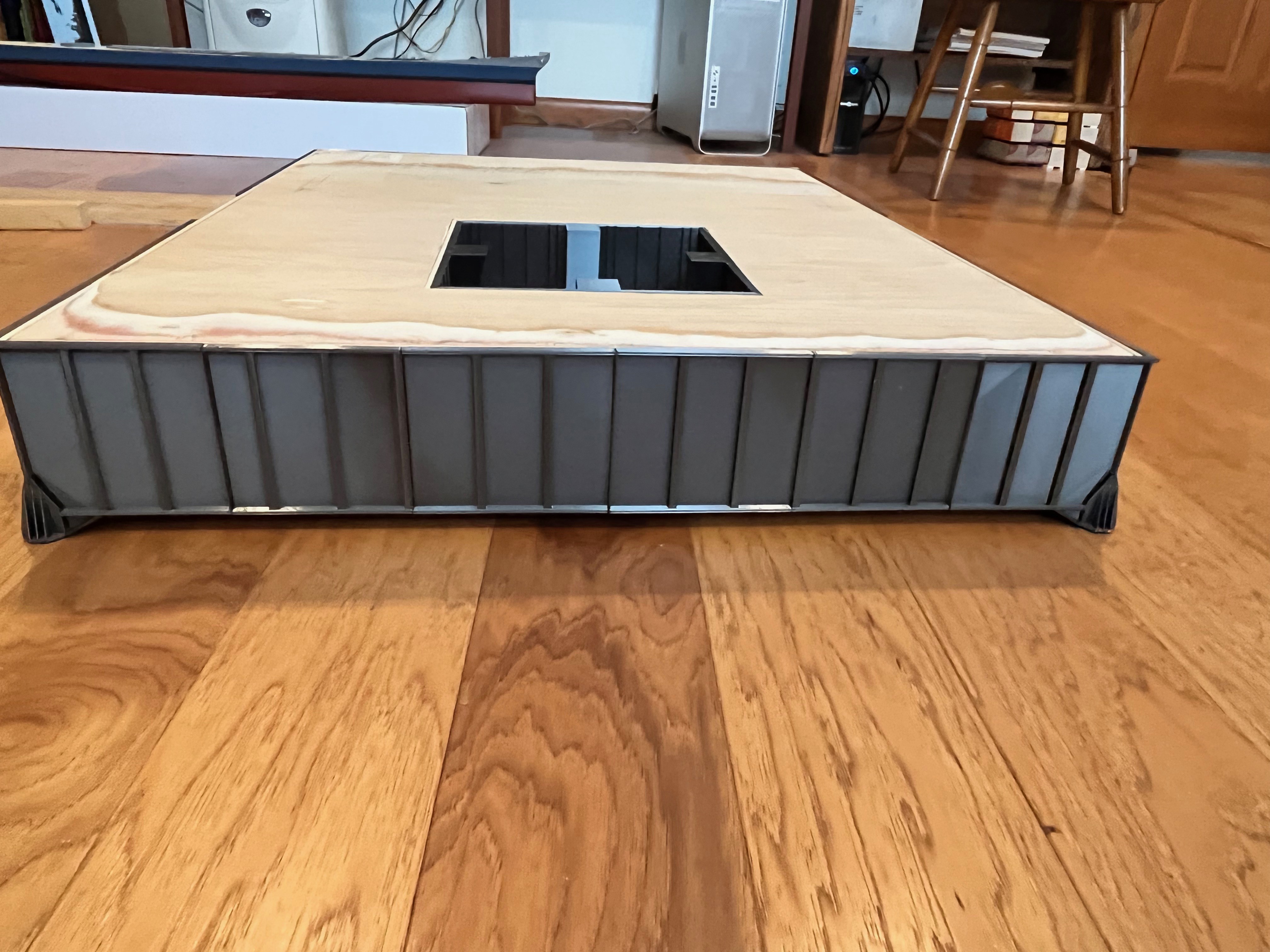
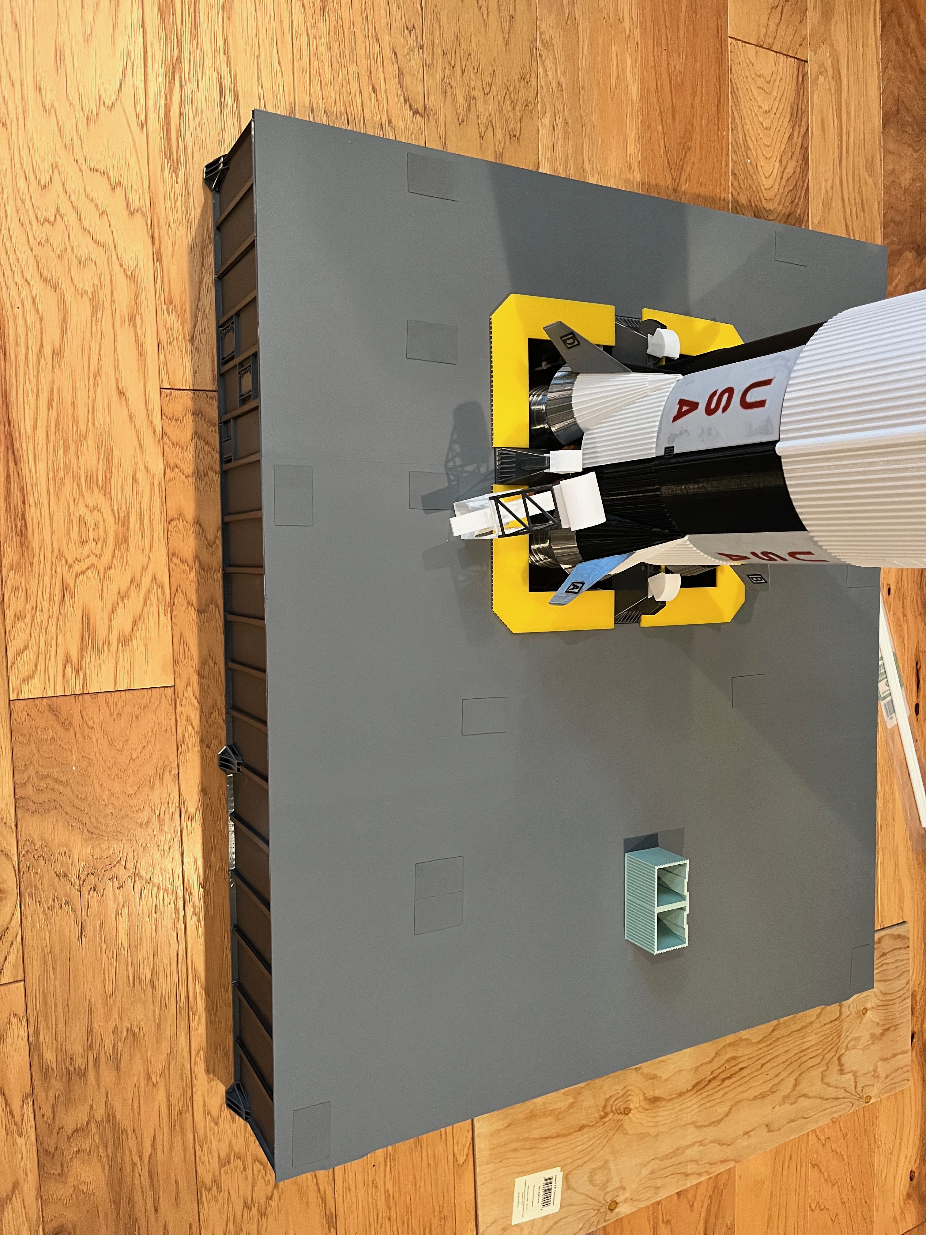
I am working on the Saturn V and realized it's looking a lot like fall out there so I wanted to complete the wooden box structure of the launcher while the temperature in the garage is perfect for wood working. I had plenty of scrap wood from other projects. You can say the box is 31" x 26 1/4", but it's hard to grasp just how big that is until you start to build it. The crawler is small by comparison.

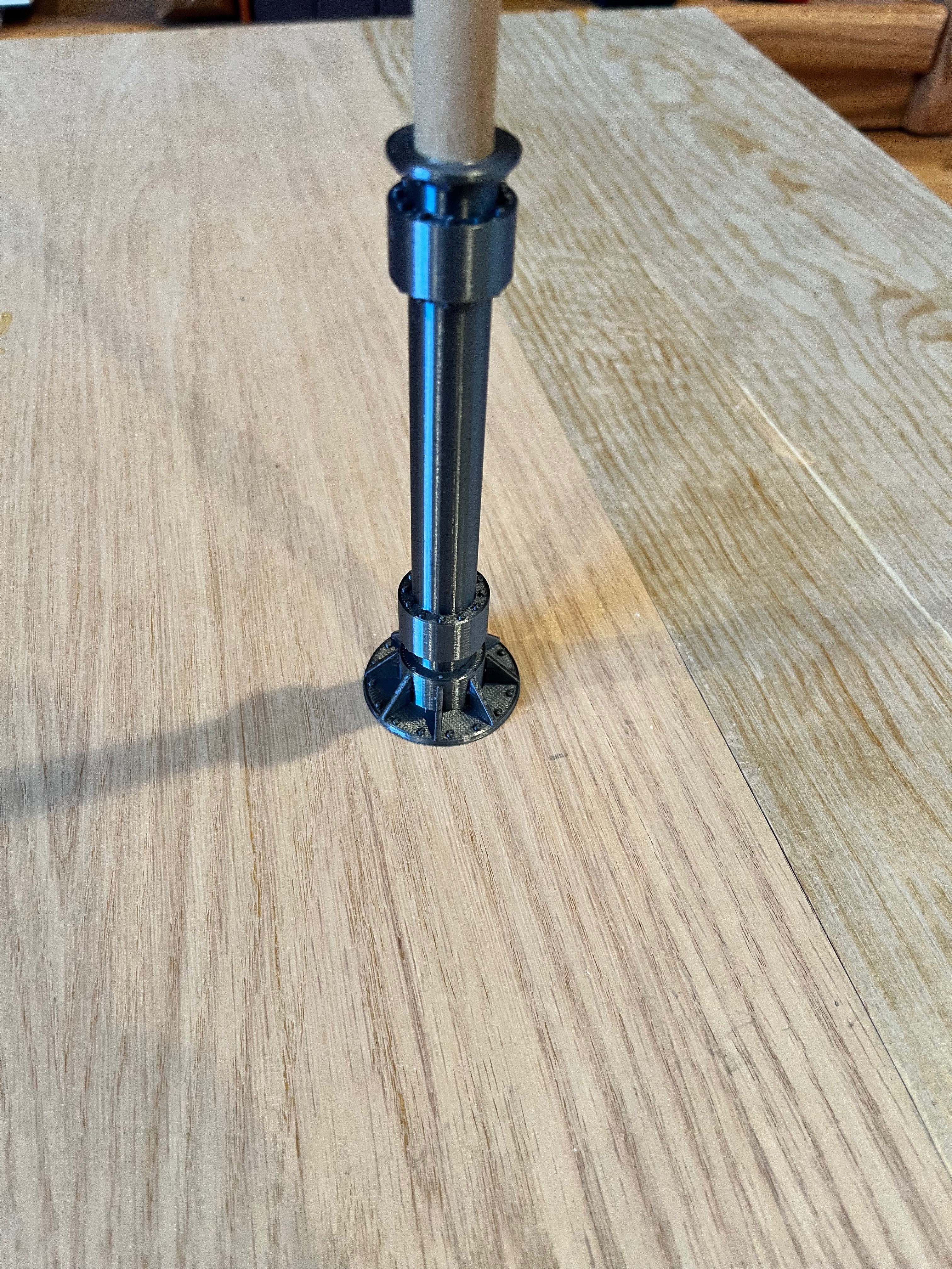
The box is fairly heavy and I want to be able to park the crawler underneath without putting all that weight on the crawler itself and be able to pull the crawler out occasionally. I went ahead and drew up the three pier types, but wanted added strength as these 6 piers will hold up all that weight and the plastic may snap if pushed on so I created a hole through the middle to insert a 1/2" wooden dowel. The dowels will go up into the box through holes and be epoxied in place. That should give plenty of strength. This is the type 3 pier.
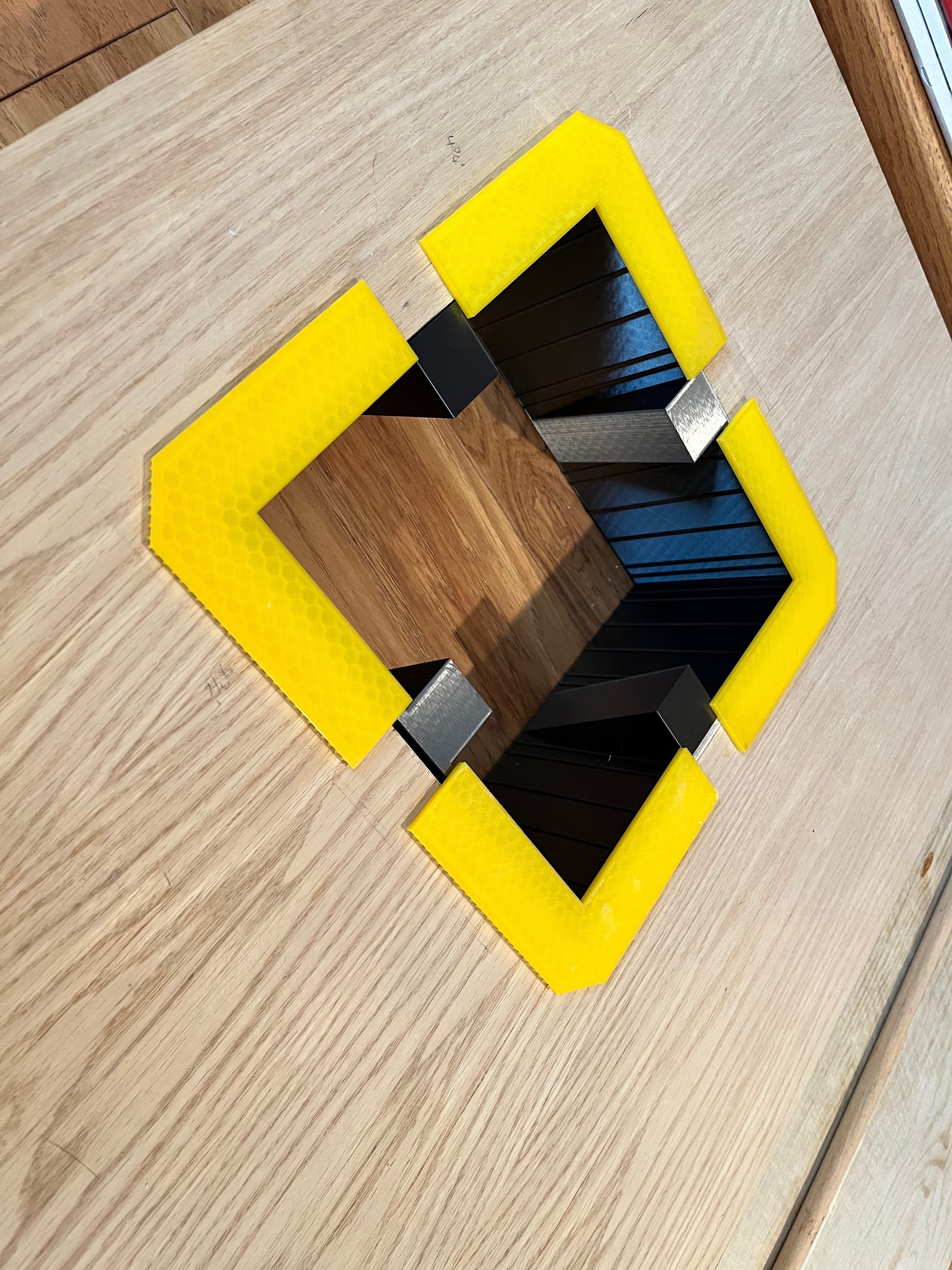
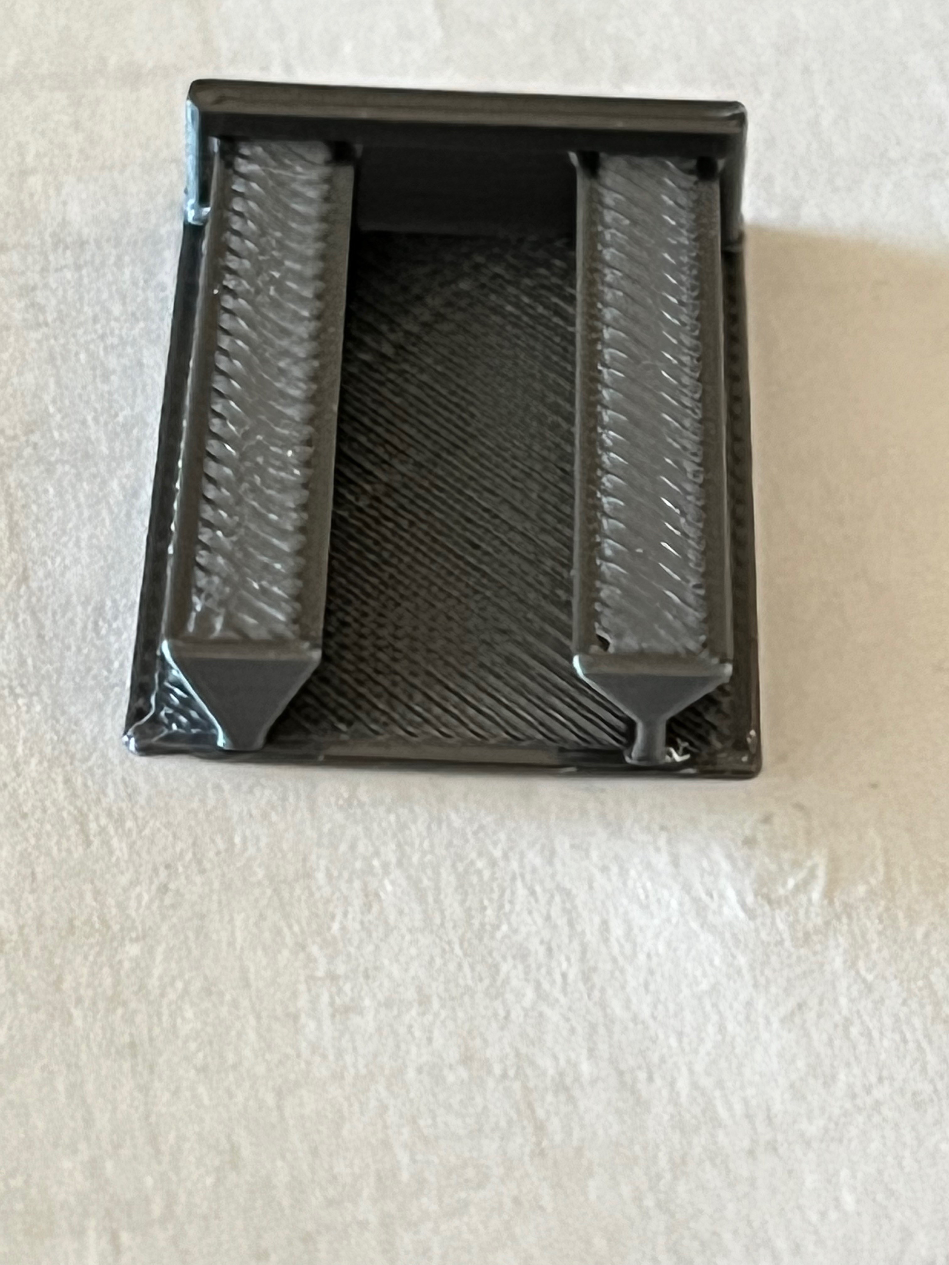
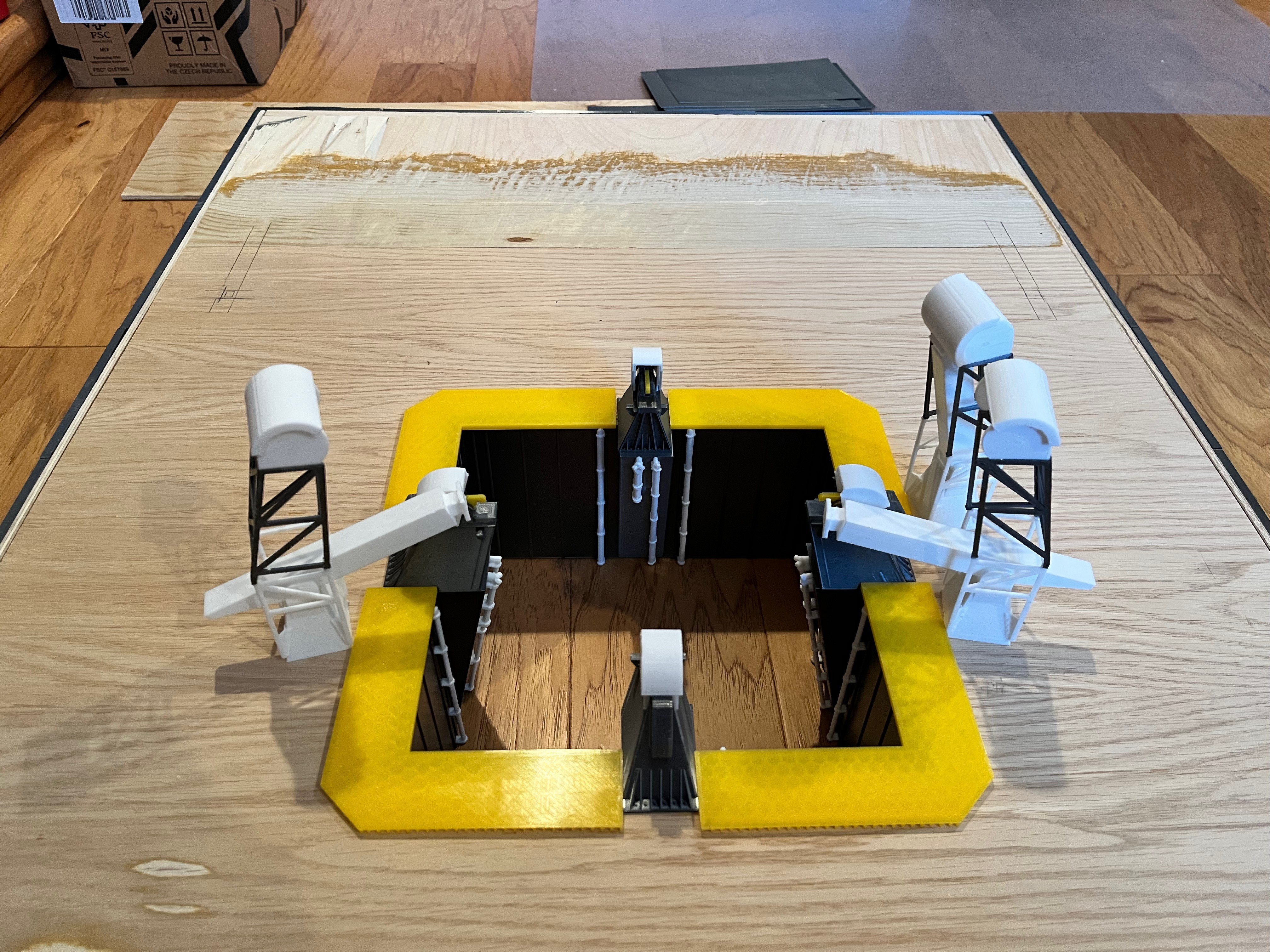
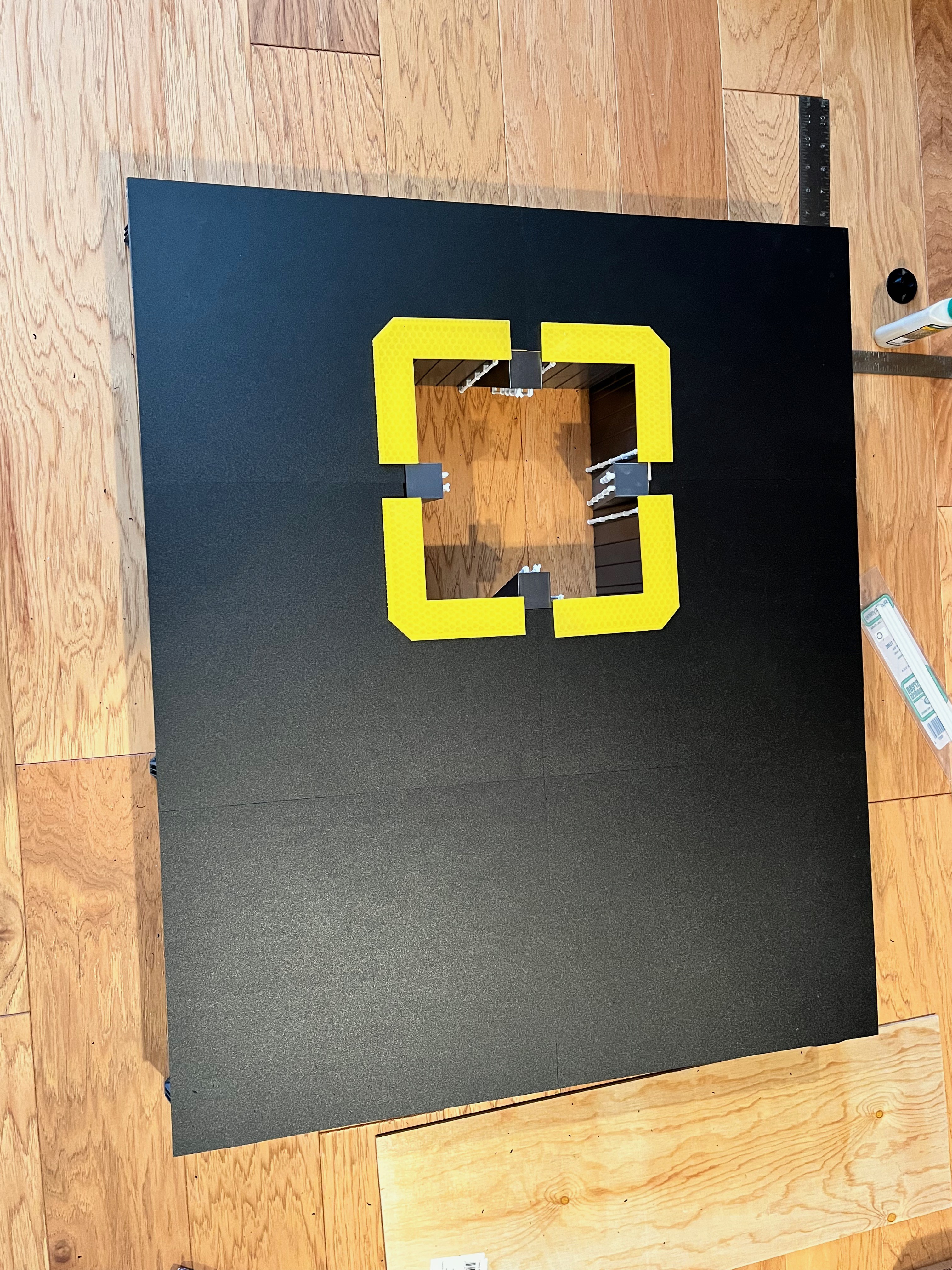
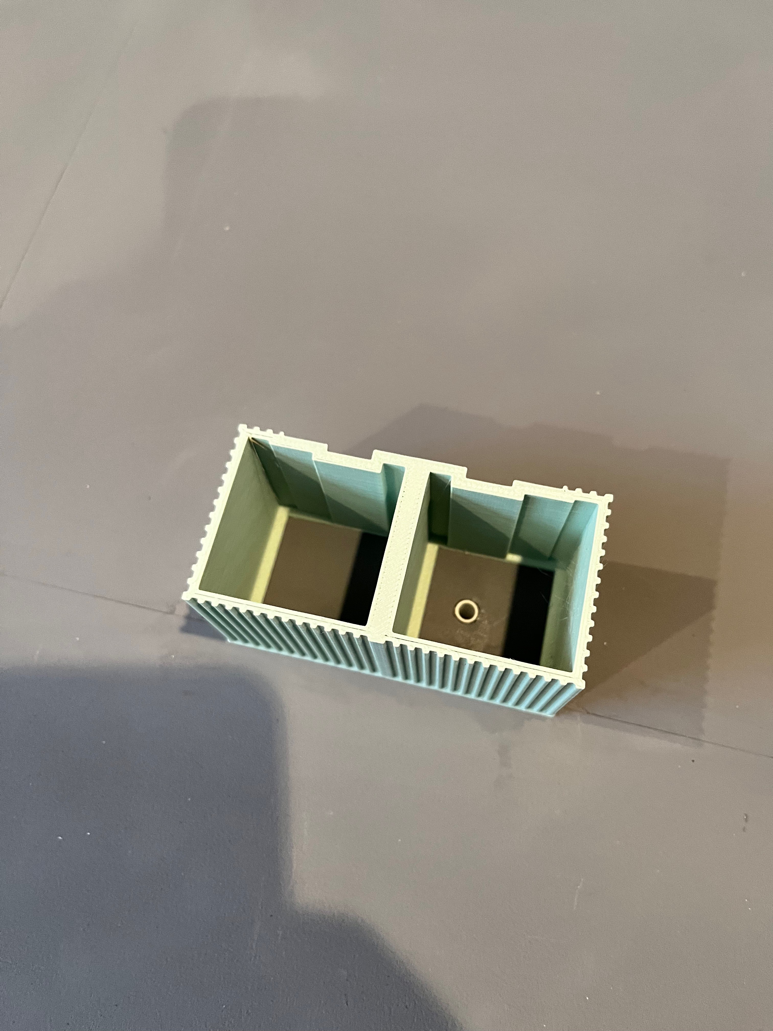
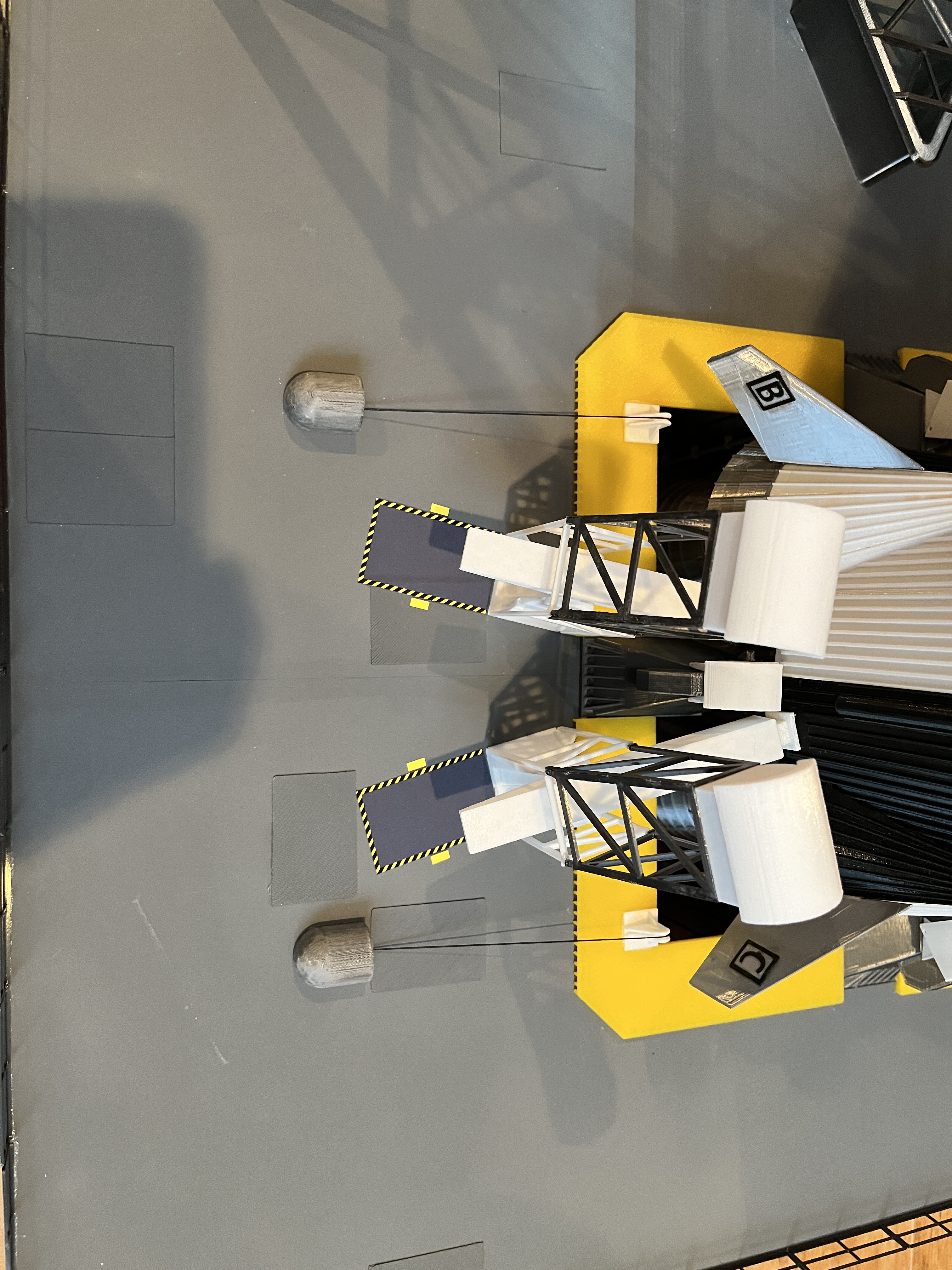
I have printed the four engine chamber walls and separate yellow engine warning plates. I like the color the yellow adds. I may reprint the warning plates as the yellow plastic is a bit too transparent.
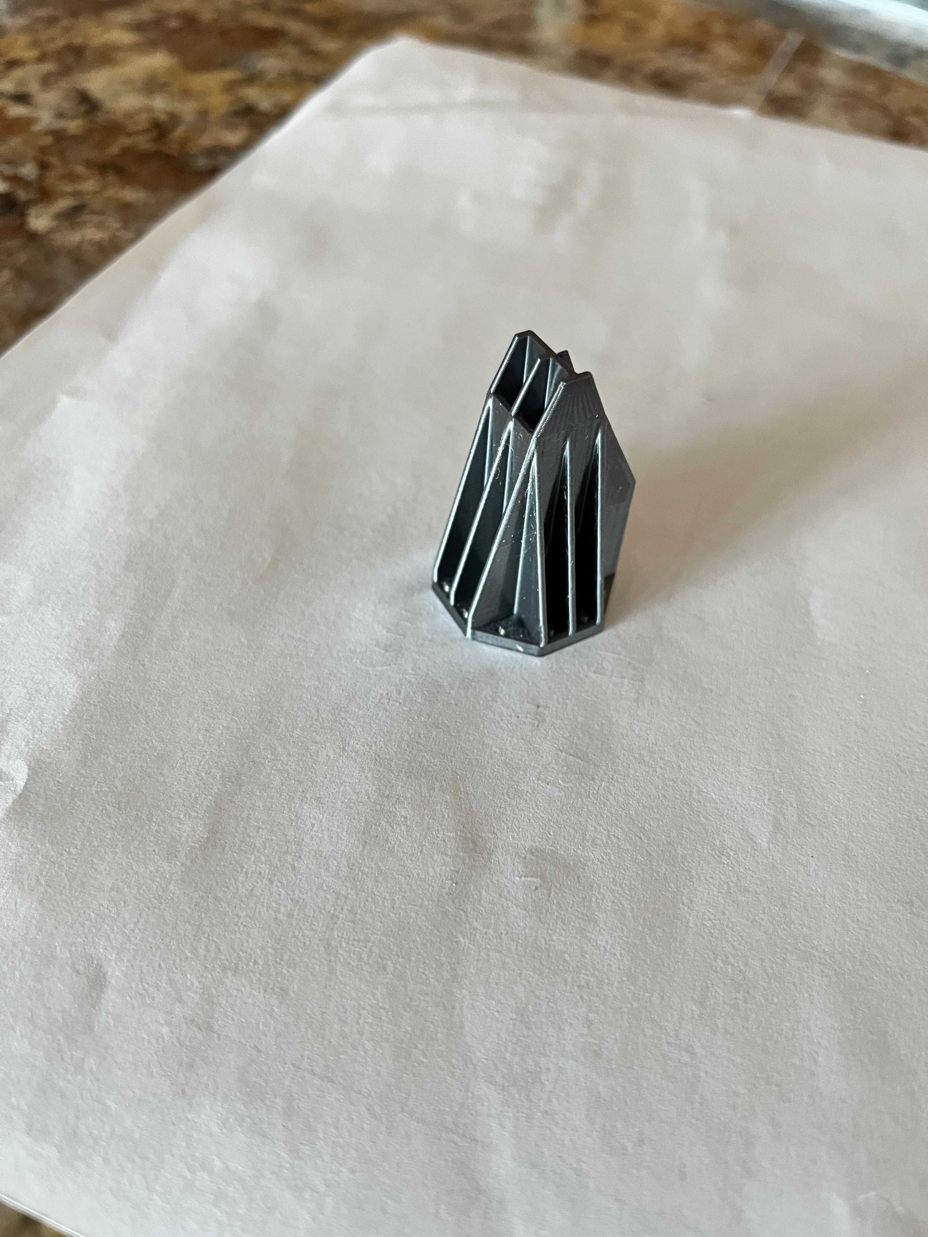
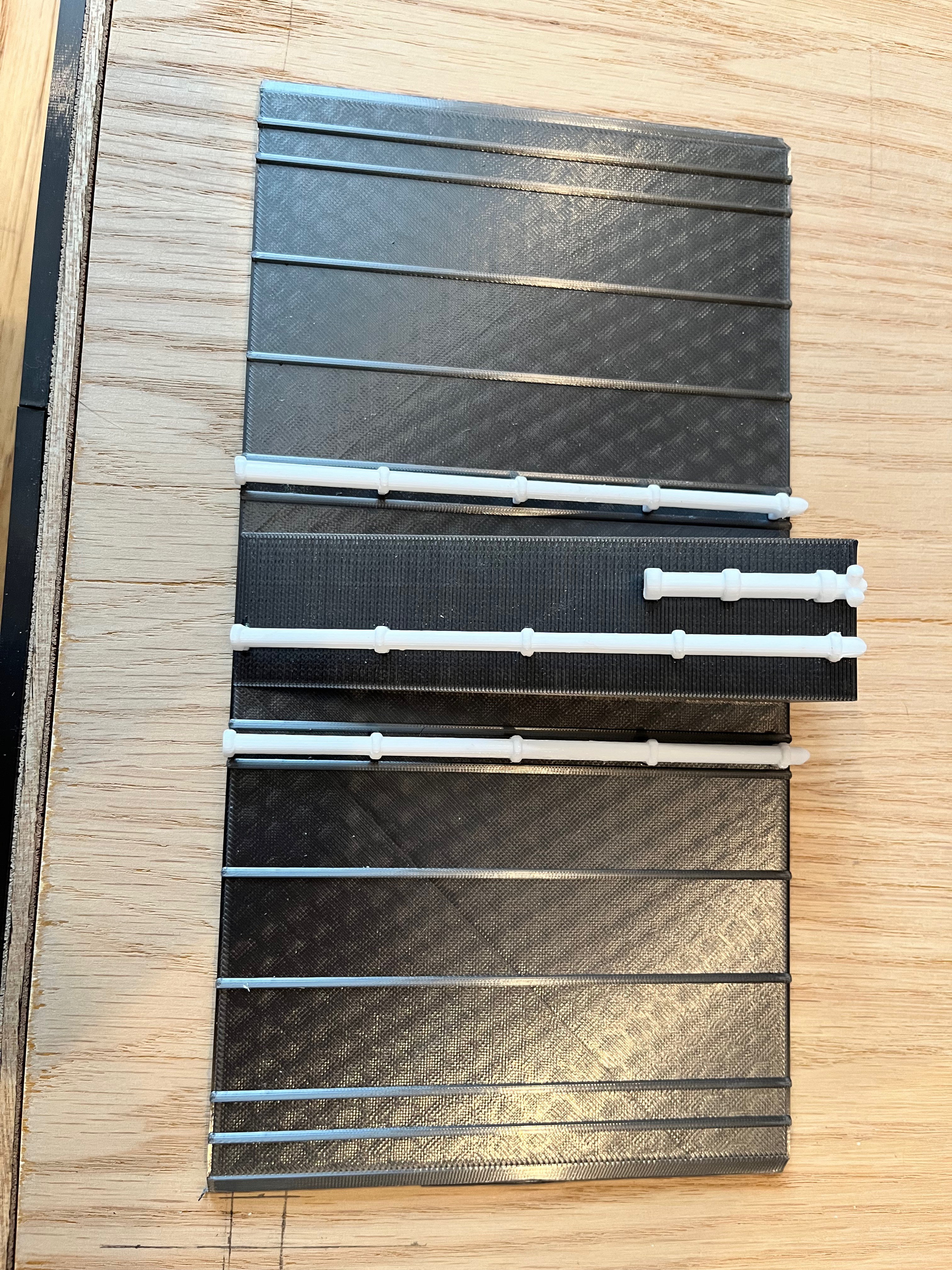
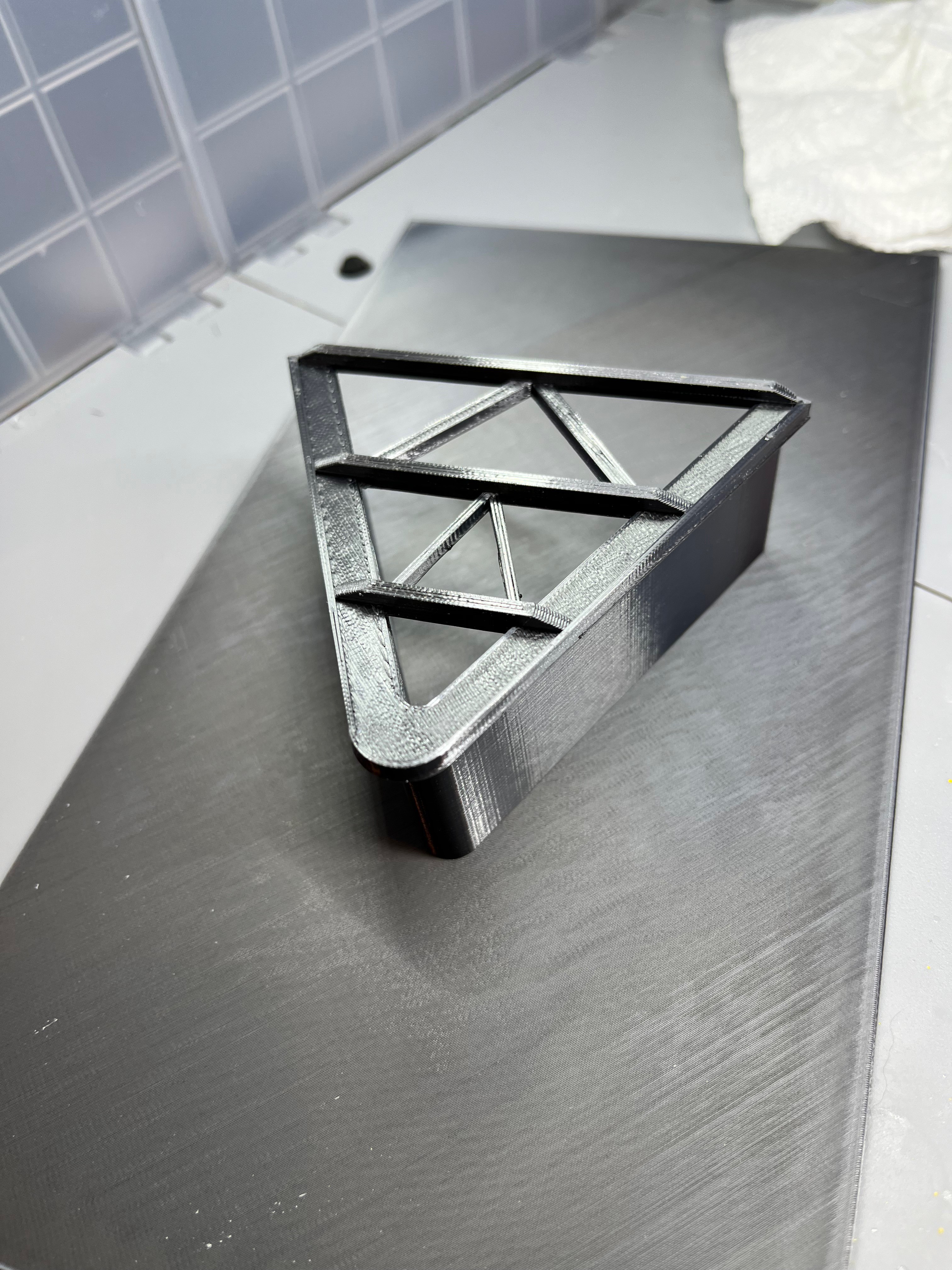
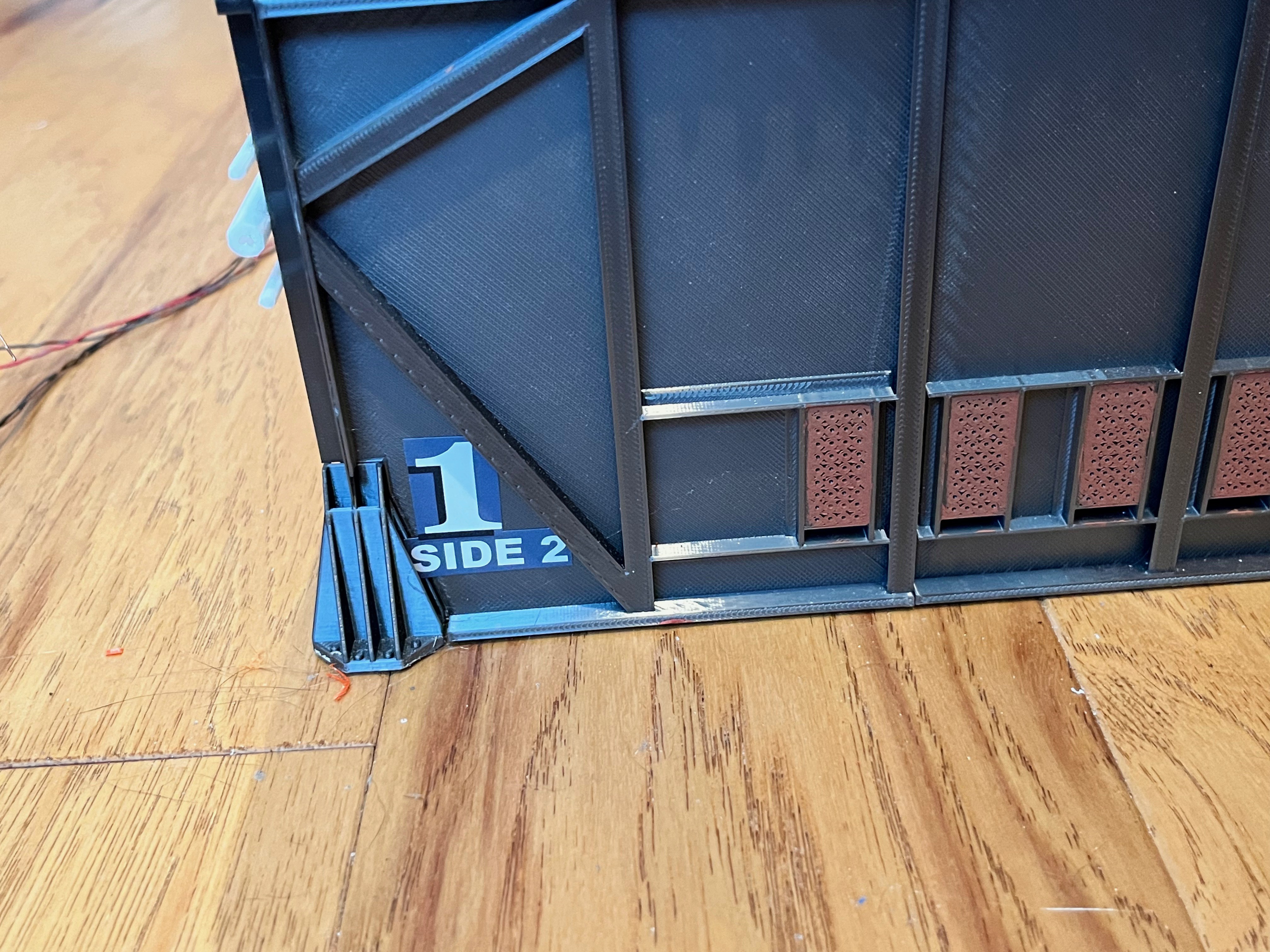
The most important part of the Launcher skins are the support interfaces where the piers attach. Six of these points have to support the entire model. At first I drew up one of the supports using the exact dimensions and printed it out only to realize that the 3/4" webbing scales down to something waaaay to thin. I decided to beef the webbing up to 1mm which is technically not to scale but is much stronger and still has a good look. You can also see I added a 1/4" hole up through the bottom. This is where a 1/4" wooden dowel will be inserted to pin the pier in place and add lateral strength. The corners of the box need to be chiseled out to fit the bottom plate so the launcher is flat on the bottom. This will also add more glue surfaces. Once these supports are epoxied in place the hole needs to be drilled out to remove the corner of the box. The 1/4" dowels can then be epoxied into place. I think this will give enough strength to support the model.


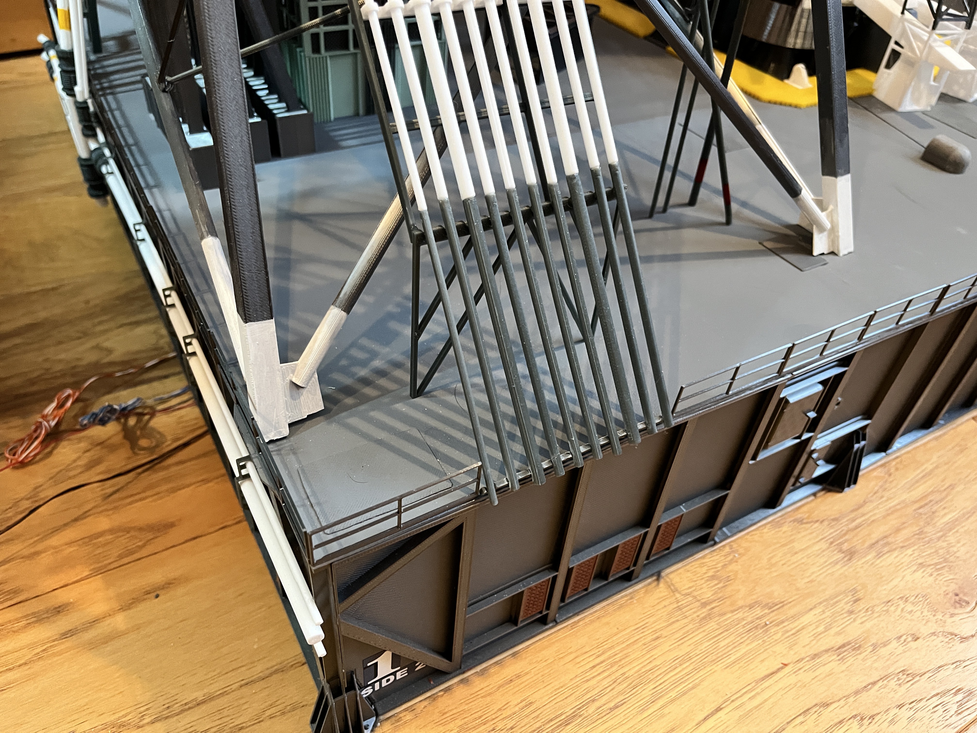
I have completed gluing the side skins to the box. I left one panel on each side for last so I could measure and adjust the skin before printing these. These skins were 4, 10, 16 & 24. Make sure the tops are flat with the top of the box. I used epoxy on the six corner supports for added strength. Once the glue dries, drill out the holes on the undersides to 1/4" for the dowels. I will add the piers and the rest of the side bling once the model is further along. I don't want fragile pieces to break off. Now on the printing the top skins.
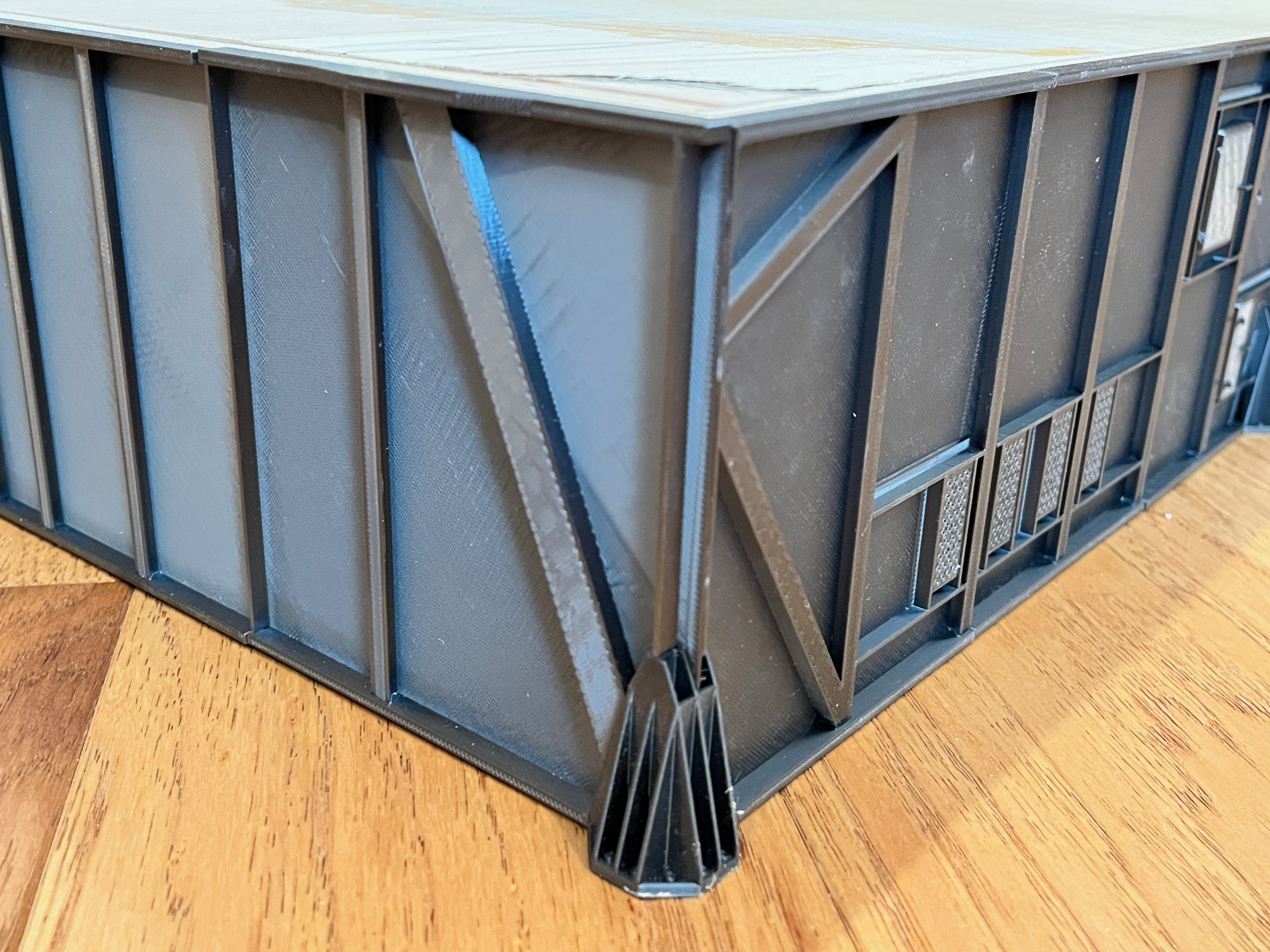
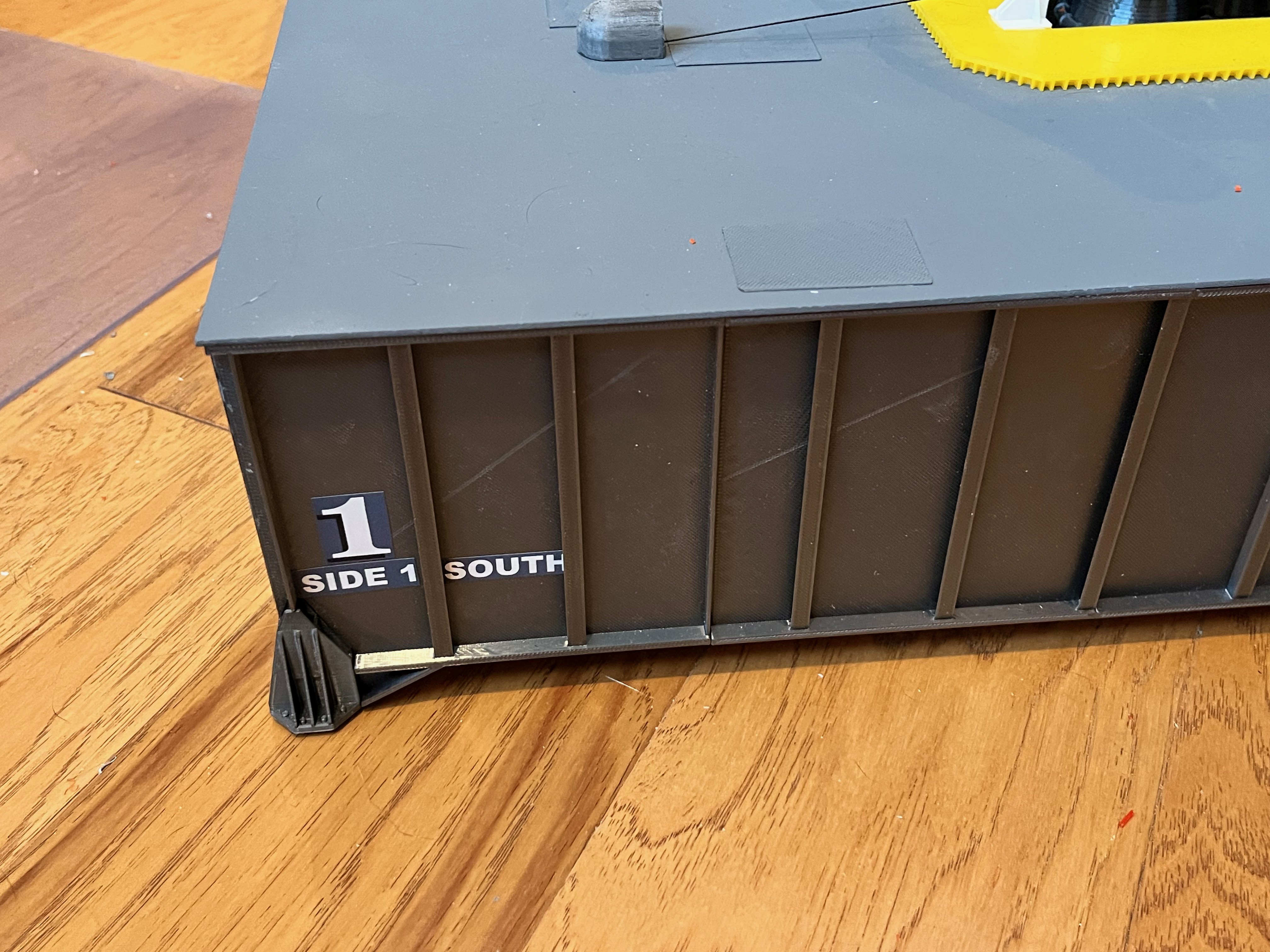
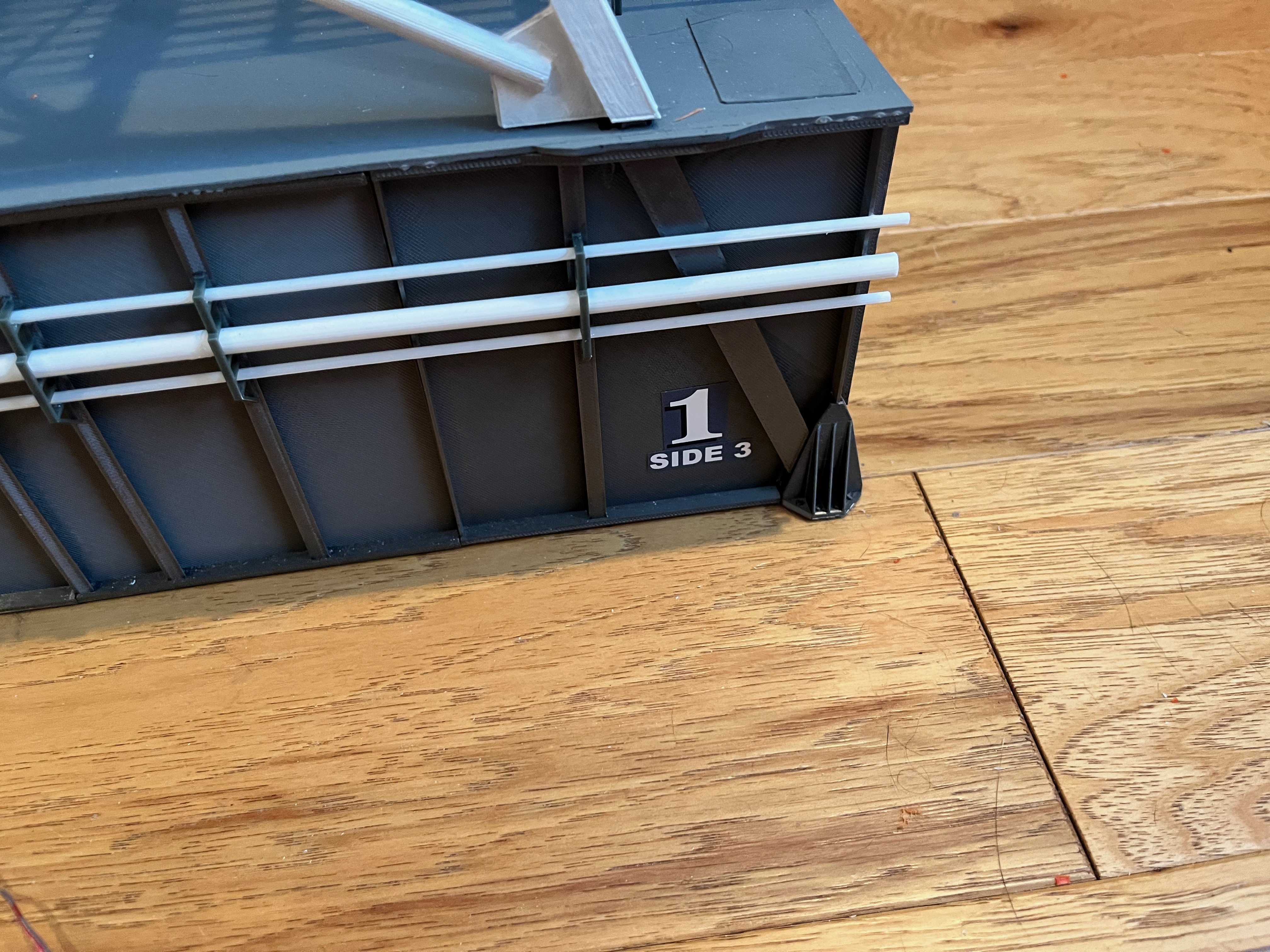
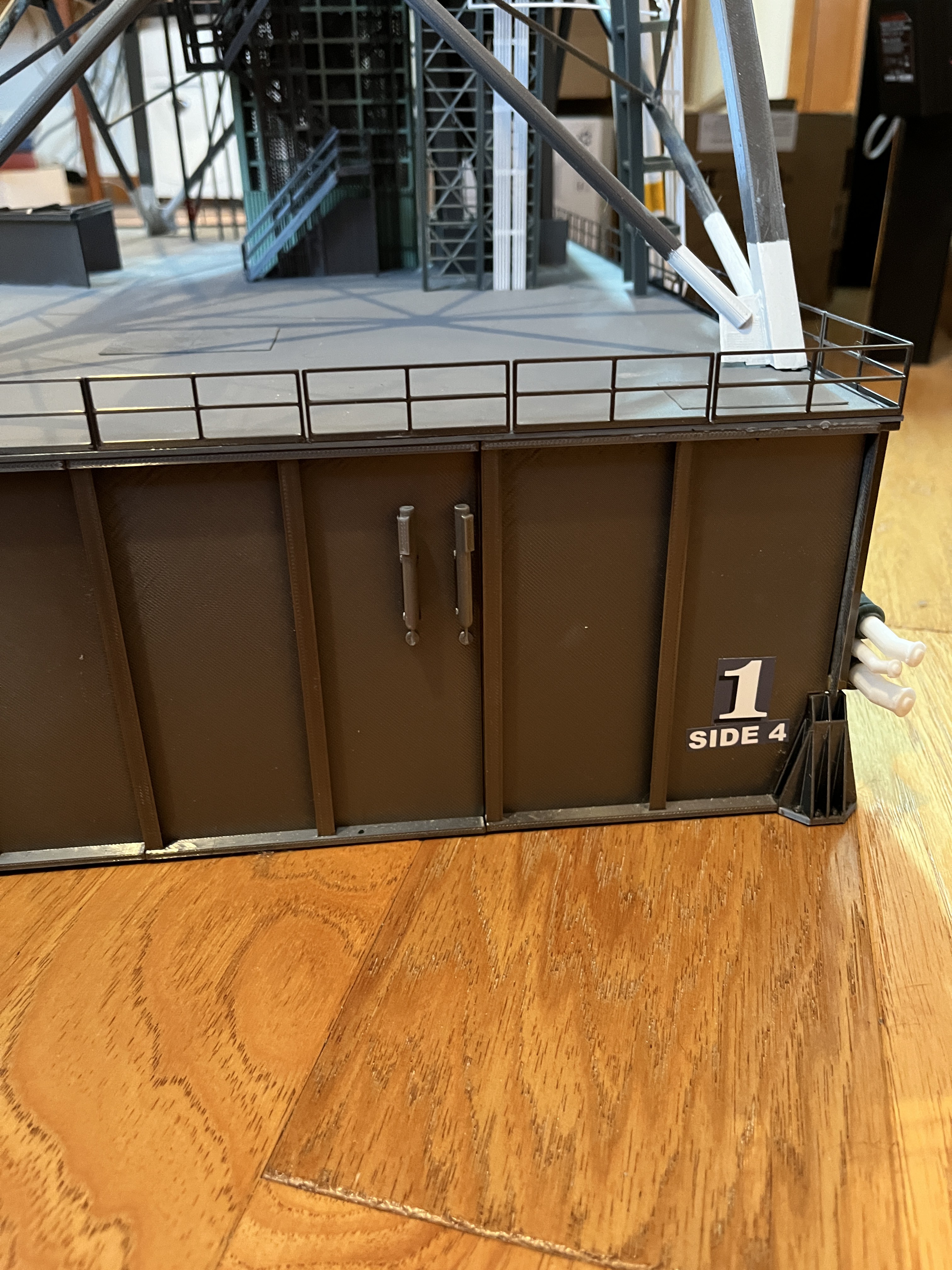
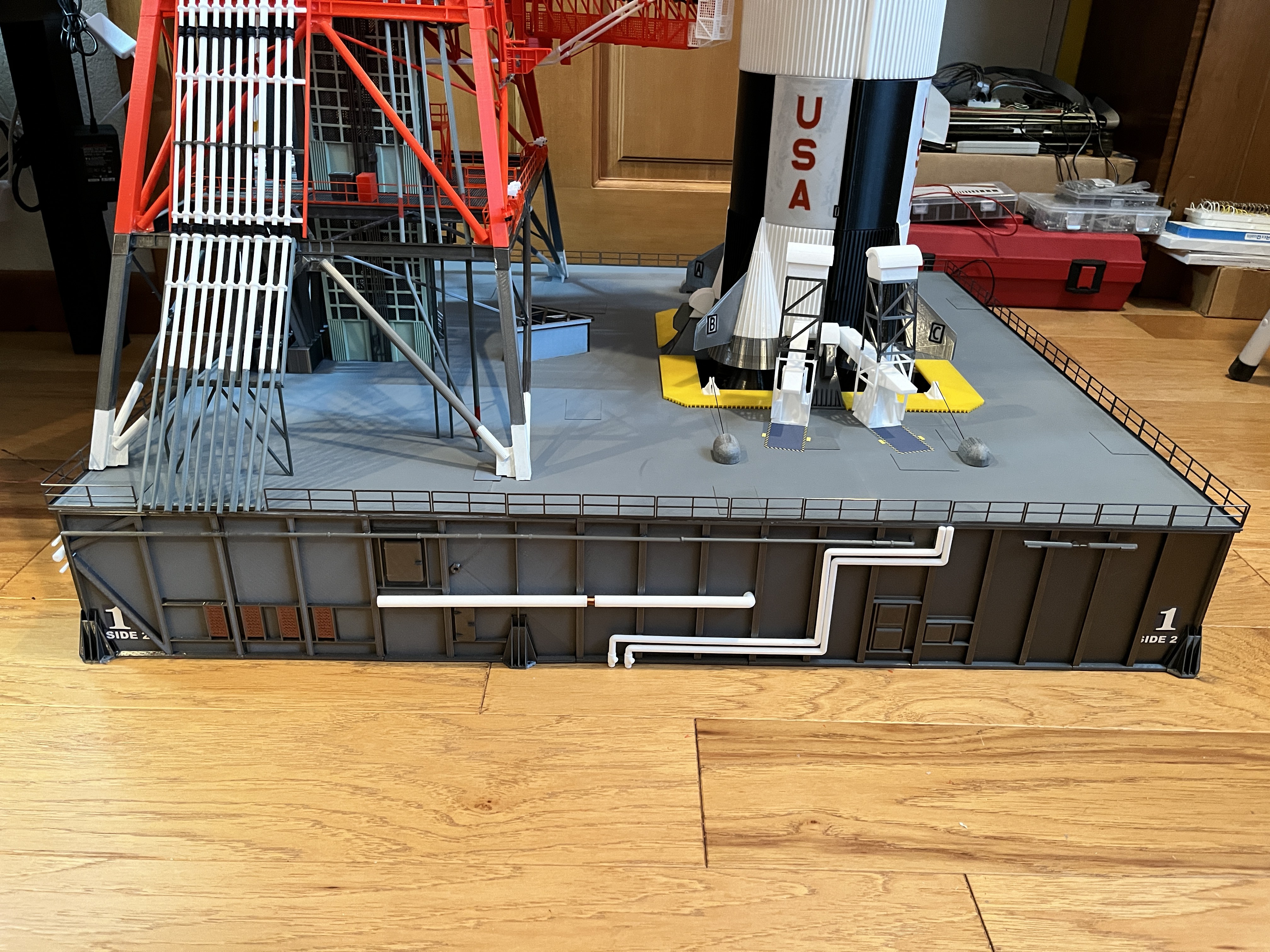
Side 1; Notice that the underside of this side of the launcher is elevated off the floor.
On this cross section of the model you can see this feature. The more you study these structural drawing, the more you will understand the model.
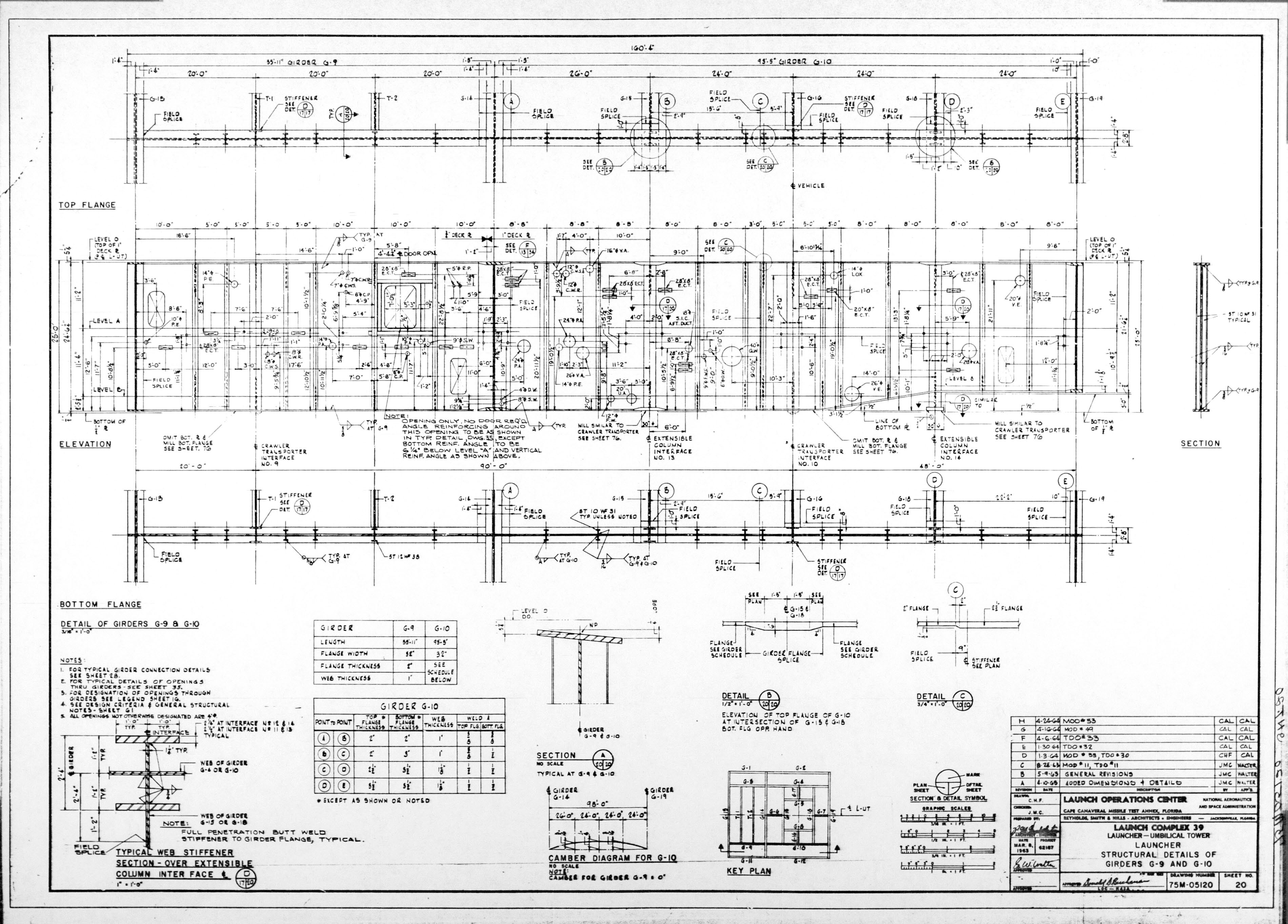
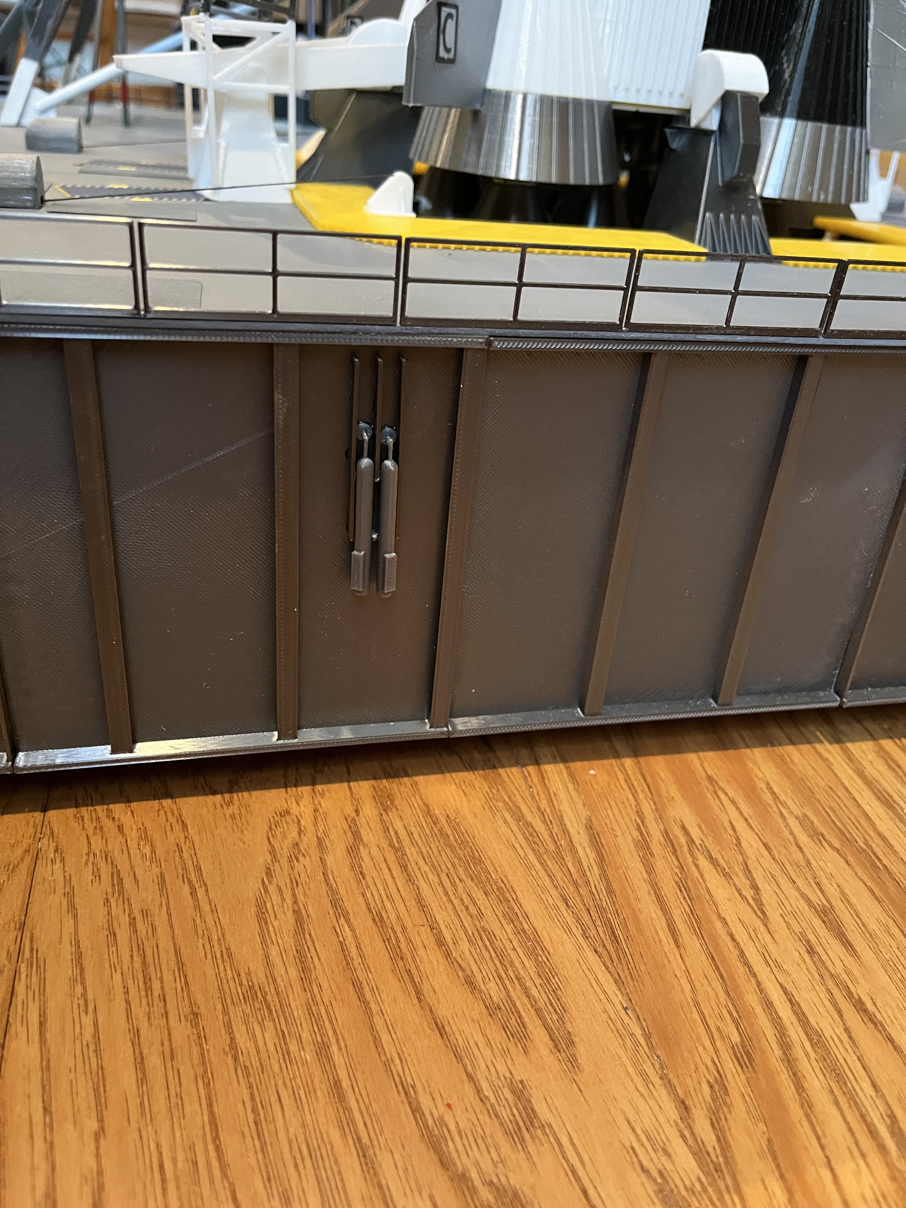
This is the corner of Side 2/3. I refer to everything by side and level.
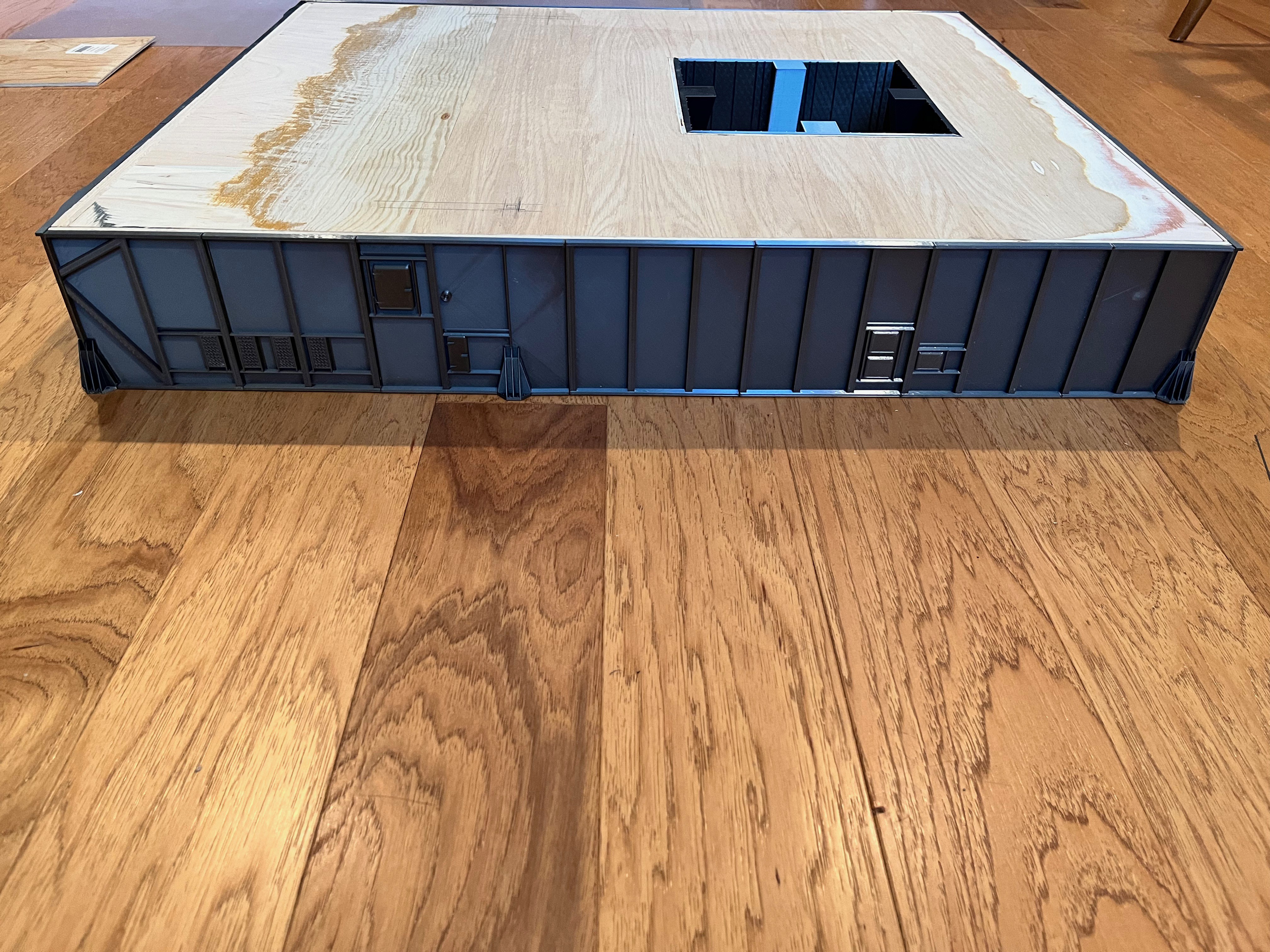
Side 2;
Side 4:

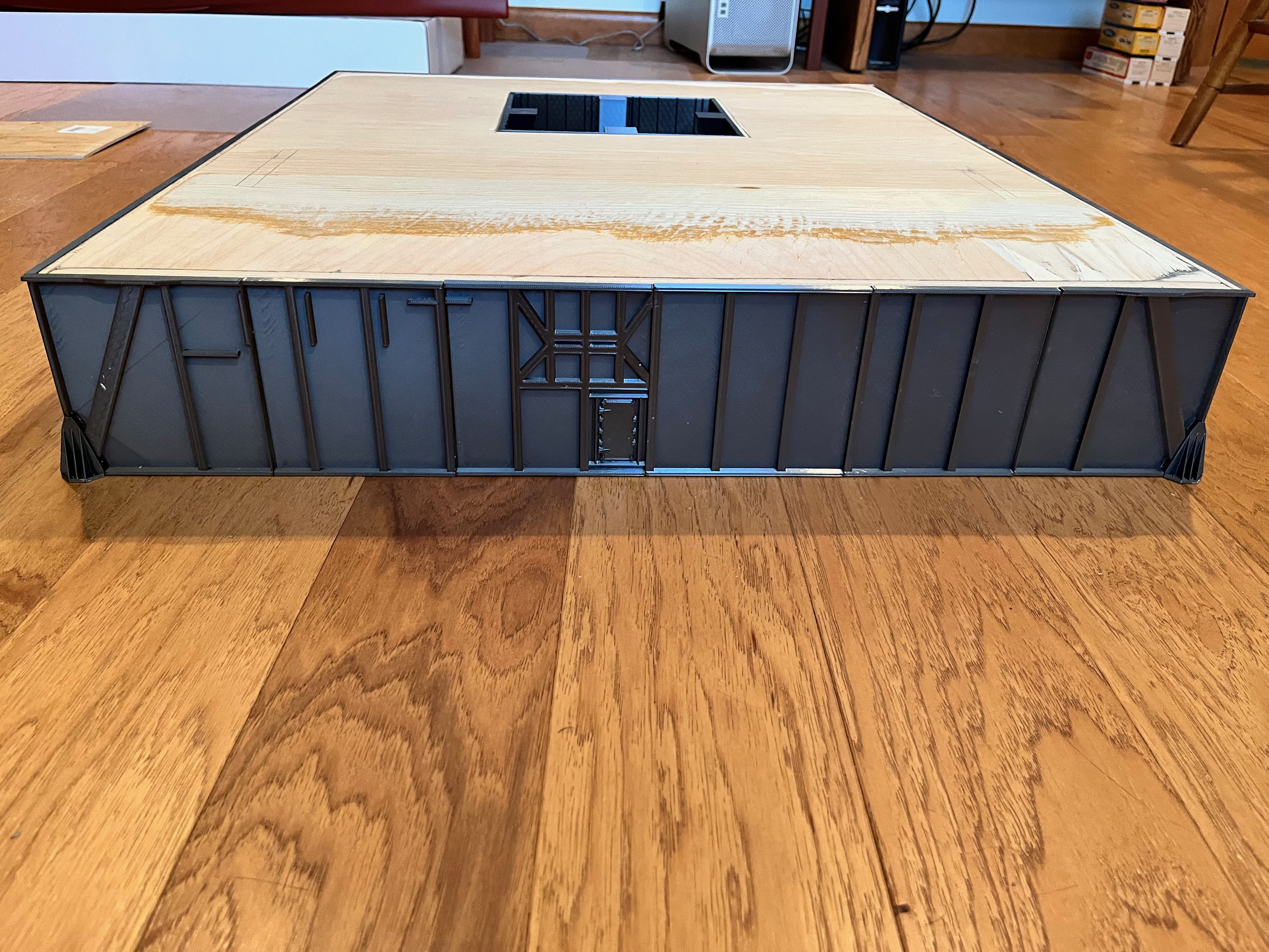
Side 3:
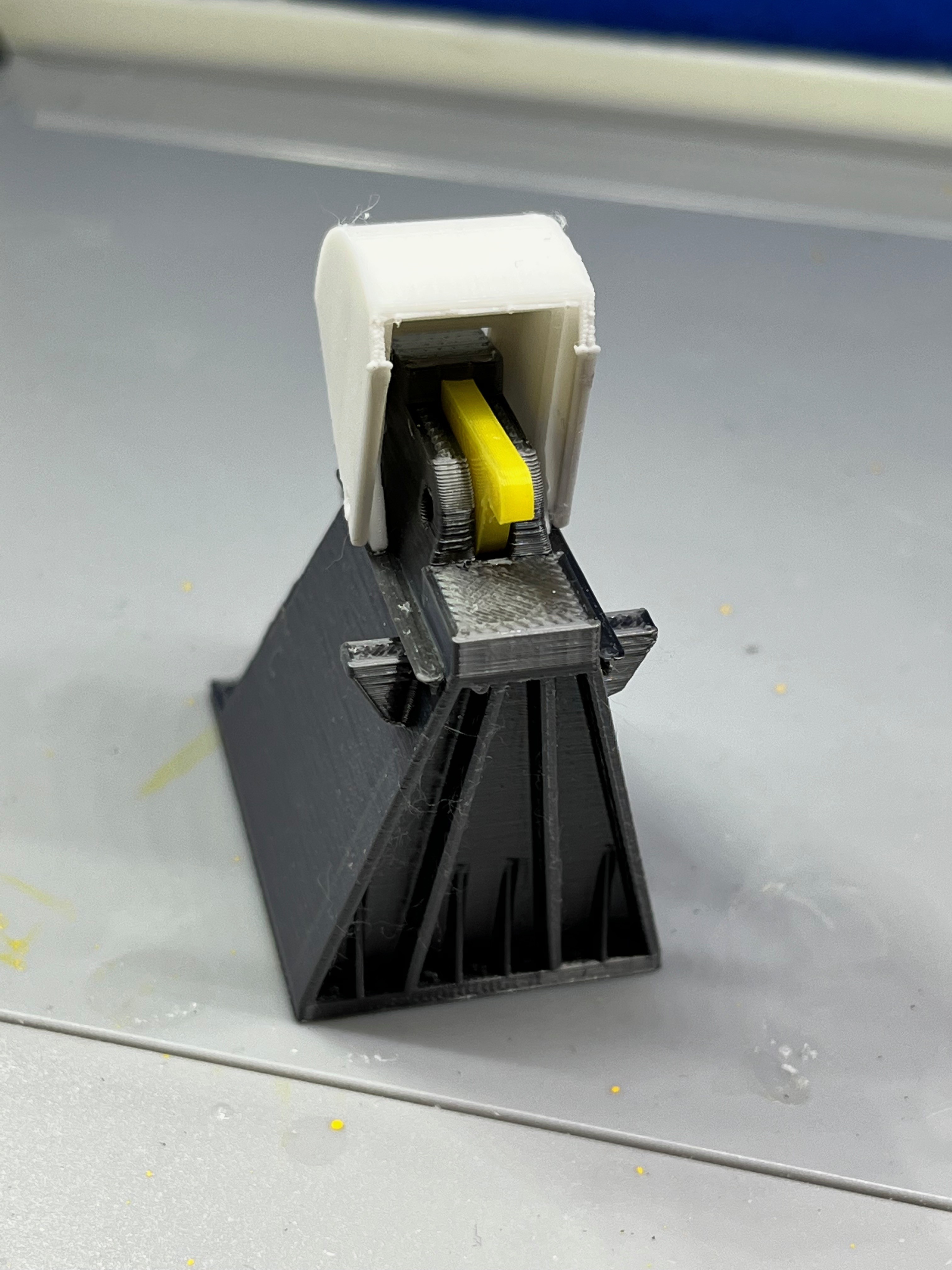
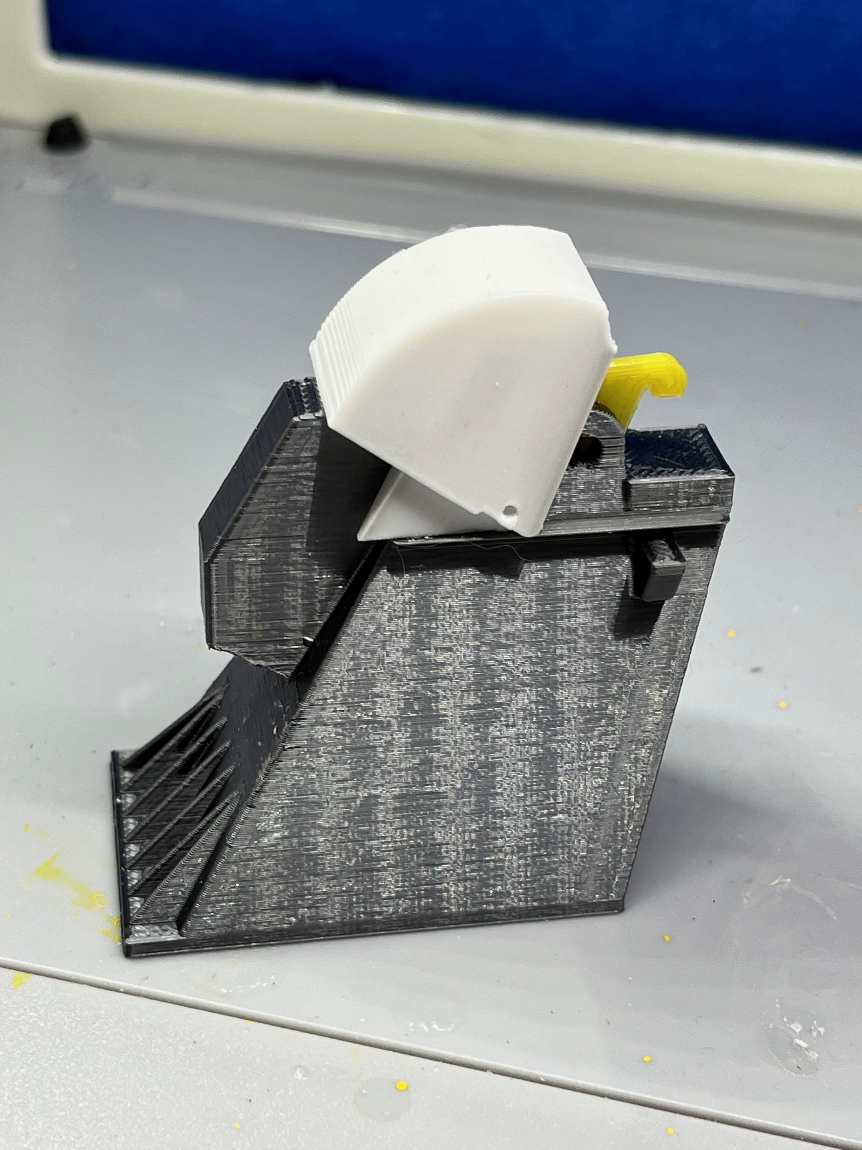
Another part I didn't have to design.
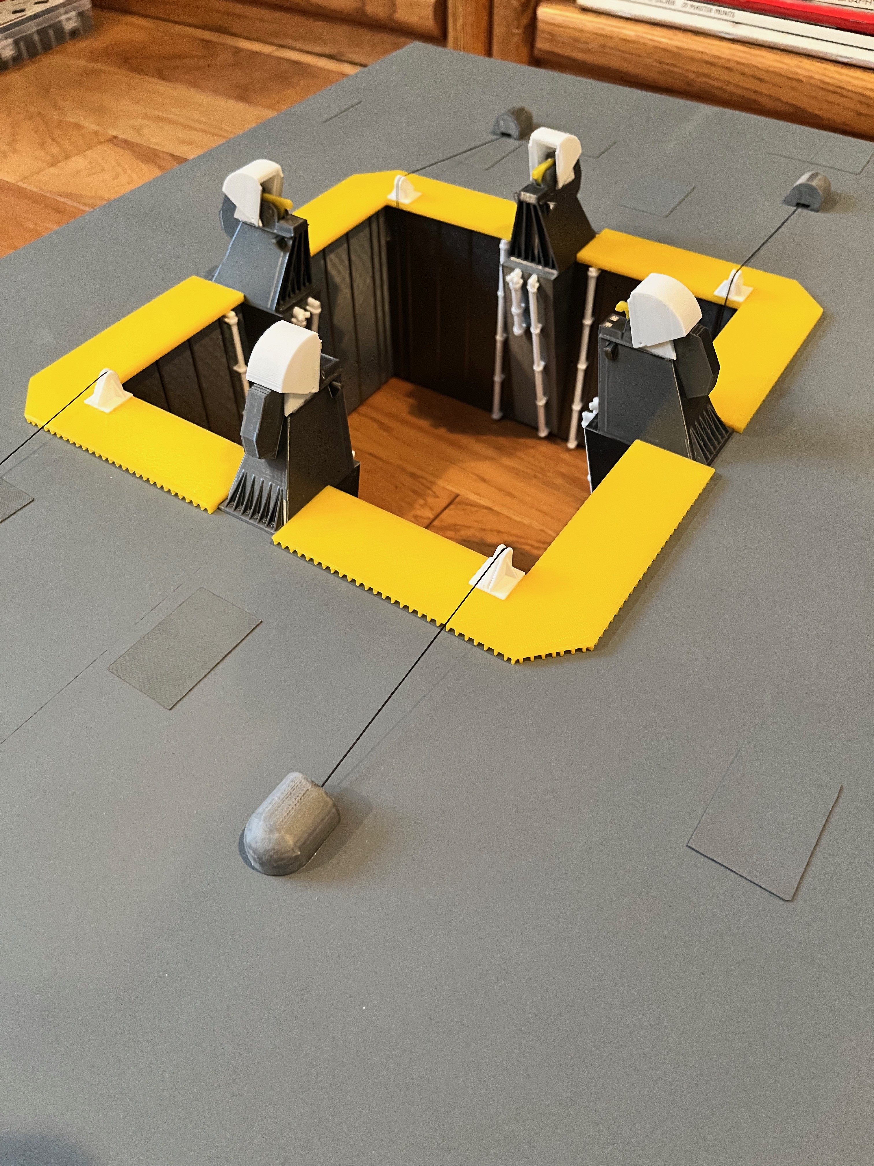
I went ahead and printed Farscape's tail service masts. They are accurate enough and operable. As I wait for parts to solve the deck issues I continue to work on the next pieces and I've started to print the second stage of the Saturn V. I'm also waiting for a second printer to arrive. The printer is definitely the long pole in this process.


To make it easier to get wires up through the launcher platform later on, I installed a piece of 5.5mm hollow tube I had left over from another project. After figuring out where the elevator shaft would be, I drilled holes and pushed the pipe through. The pipe was glued flush with the top and then flush cut with the bottom.

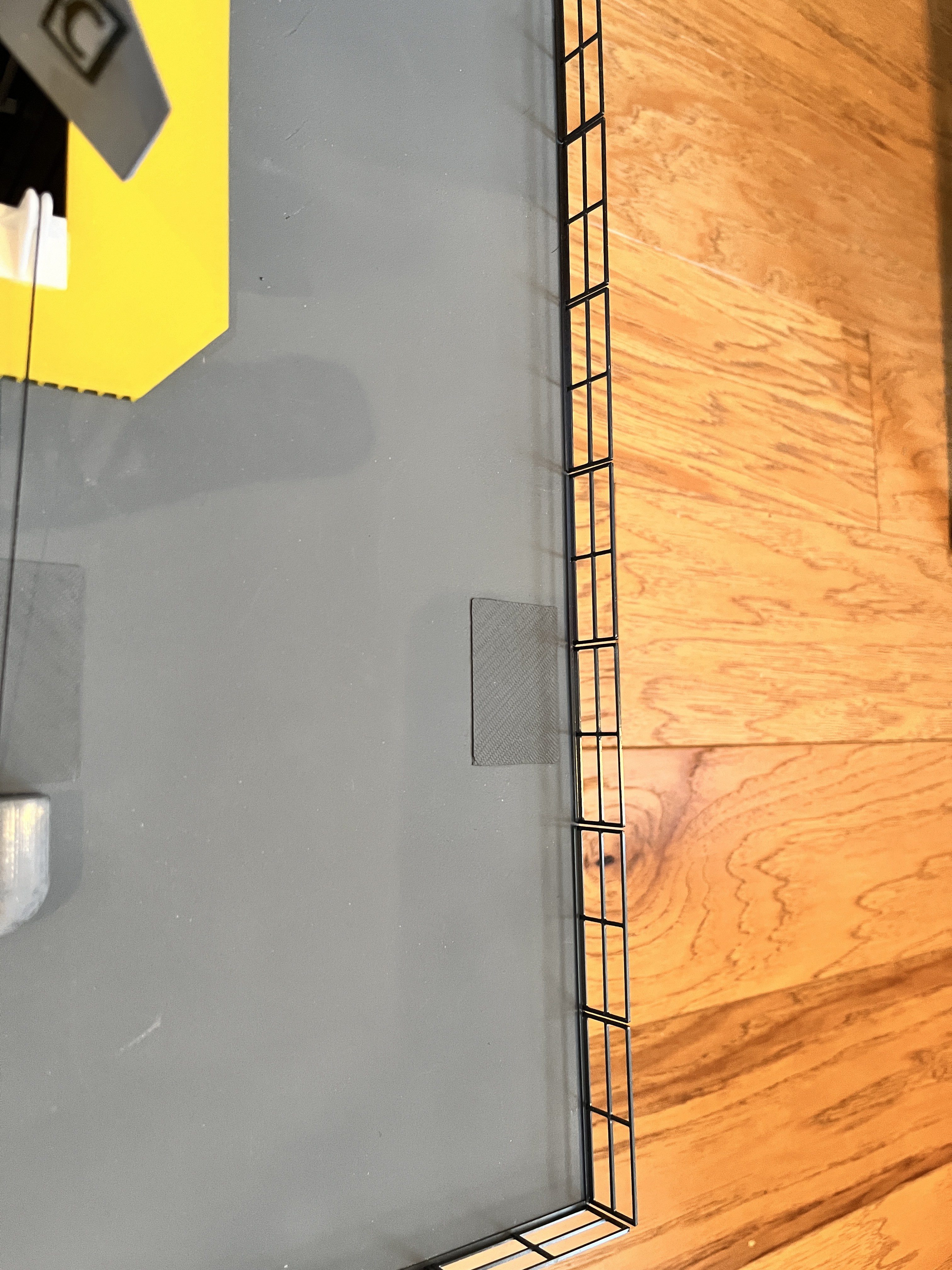
You will notice that there are little access plates on top of the model. Refer to 75M-05012 pages 12 and 13 for their placement.
I have now added the decals to the sides. Notice on side 3 the top surface has a bulge where the tower legs come down.

I still need to add some additional piping on the sides, some decals on top and the perimeter railing.
The launcher railing is on. I chose to make my own to match the look of the other railings on the model. I chose not to add the gutters. Here are how the parts lay out:
Short sides (side 1 &3): 6 - double sections and 1 - one and a half section
Side 2: 6 - double sections and 2 - single sections
Side 4: 8 - double sections
The two single sections of side 2 are on either side of the ECS pipes.


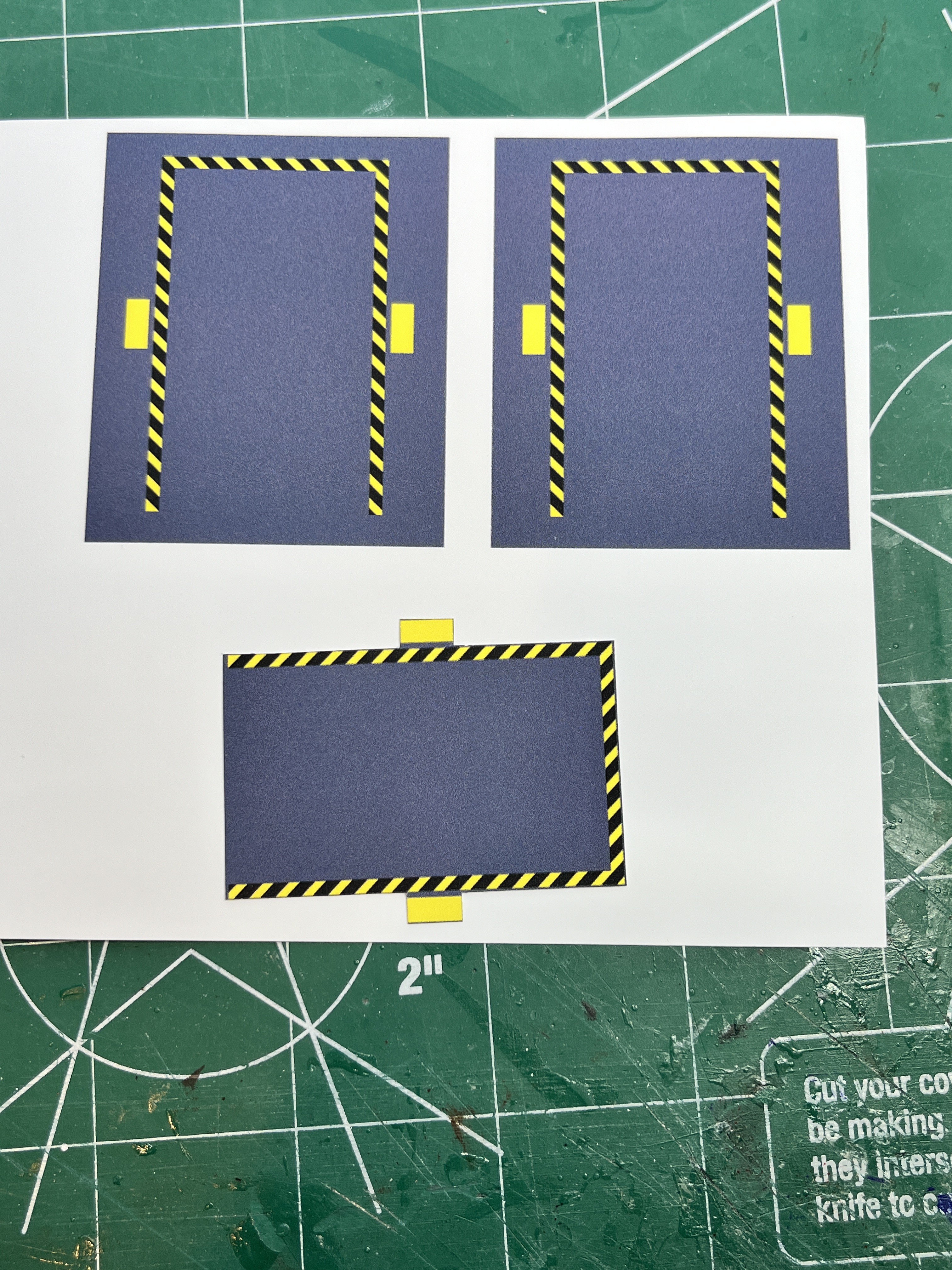
Here are the warning box decals. I printed them on a vinyl sticker sheet using best quality. Notice that I had the background grey extend beyond the yellow/black areas because if these areas were surrounded by white then you would have cut into these yellow/black areas to make sure a white rim was not around the part. The way this is printed you should cut them out by cutting just beyond the yellow/black areas leaving a little grey which will blend into the grey surface. This leaves very straight printed lines. I chose to leave the center section because I though it would be too hard to apply the decal without this. You may feel different. The grey is a bit darker but I figured that is OK because it is surrounded by the yellow/black border.
Here are small side vents on side 1 and side 4. There is also a pair on side 2.
Discussions
Become a Hackaday.io Member
Create an account to leave a comment. Already have an account? Log In.