I love it when I can find parts that someone else designed, it saves me time and effort. Aviator67 produced a treasure trove of add-on parts for the farscape1 LUT. After printing and assembling the Level30 floor framing along with the cable tray template I realized the cable tray template is inaccurate. I displayed the Micro Artwork level 30 picture and enlarged it to size. Matching up the template to the picture it appears the portion in the bottom of the picture is very accurate, however the upper portion is too stretched out and conflicts with the framing. It looks like I will be re-creating these parts. I will also make the cross members of this "template" look more like what is shown in the Micro Artwork picture.
John,
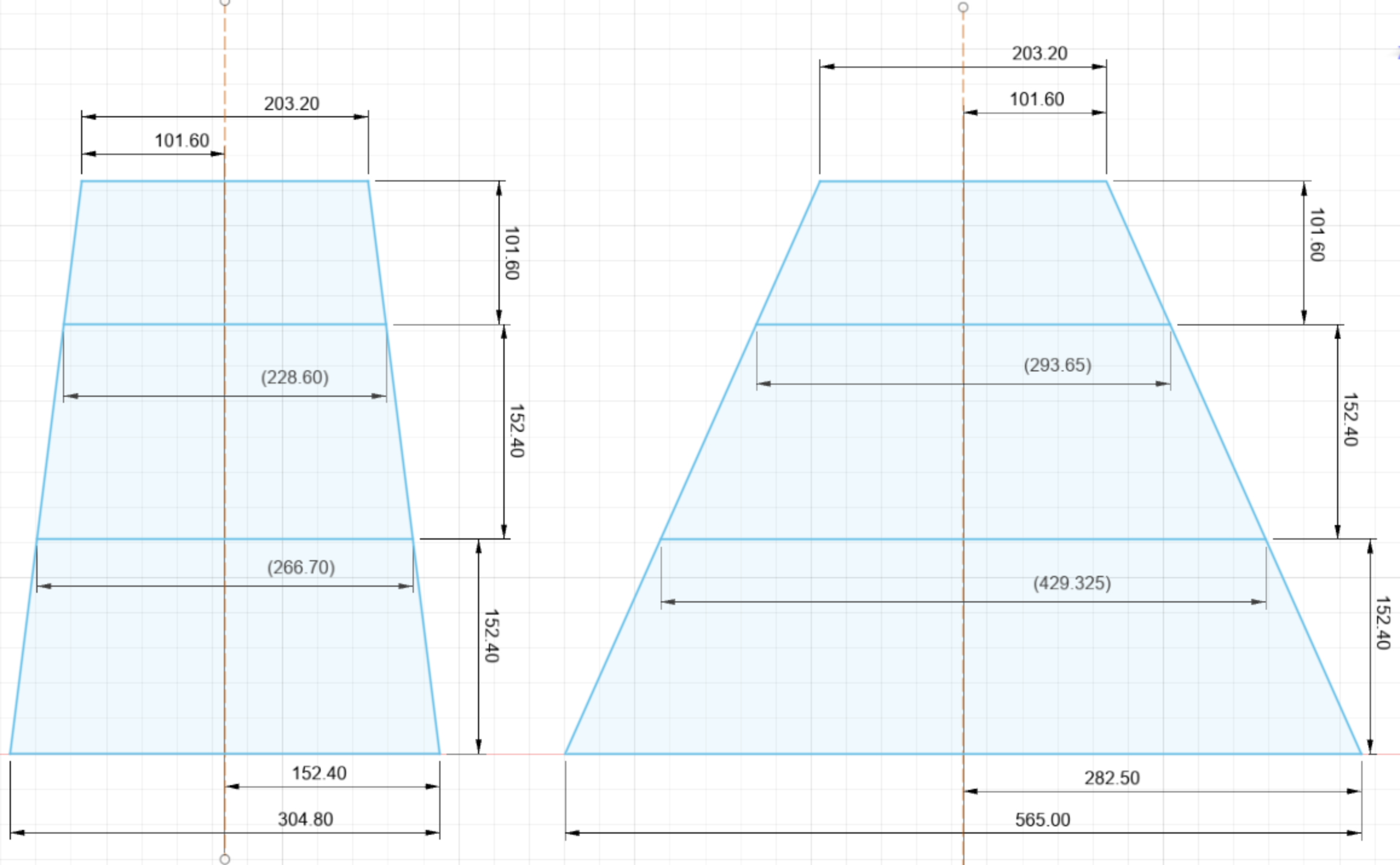
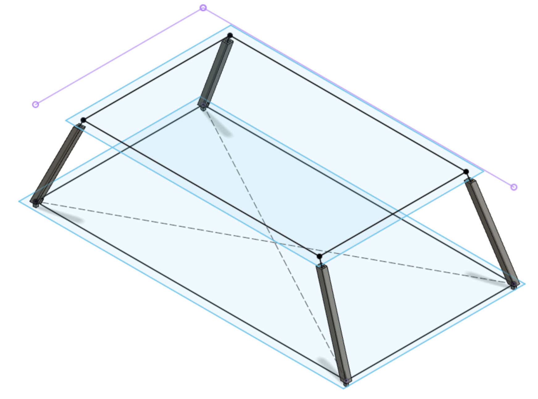
The level 30 platform should be 40' x 54'. The farscape1 platform is correct for the 40' dimension but off for the other dimension. The scaled dimensions are 250mm for farscape1 where it should be 274.32mm, off by almost 25mm, almost one inch!!! That will throw off the level 60 platform for sure. And as John says the gantry arms will all be too long as the entire tower needs to be shifted towards the Saturn V by over half an inch. I can see where this is going to take me awhile to redraw. I have started a new model page on Printables and will publish it once I get some parts drawn up.
A first, rather small start. Here are the scale dimensions of the first three floors based on pages 54 and 55 of 75M-05120. I will base the new parts on these dimensions.
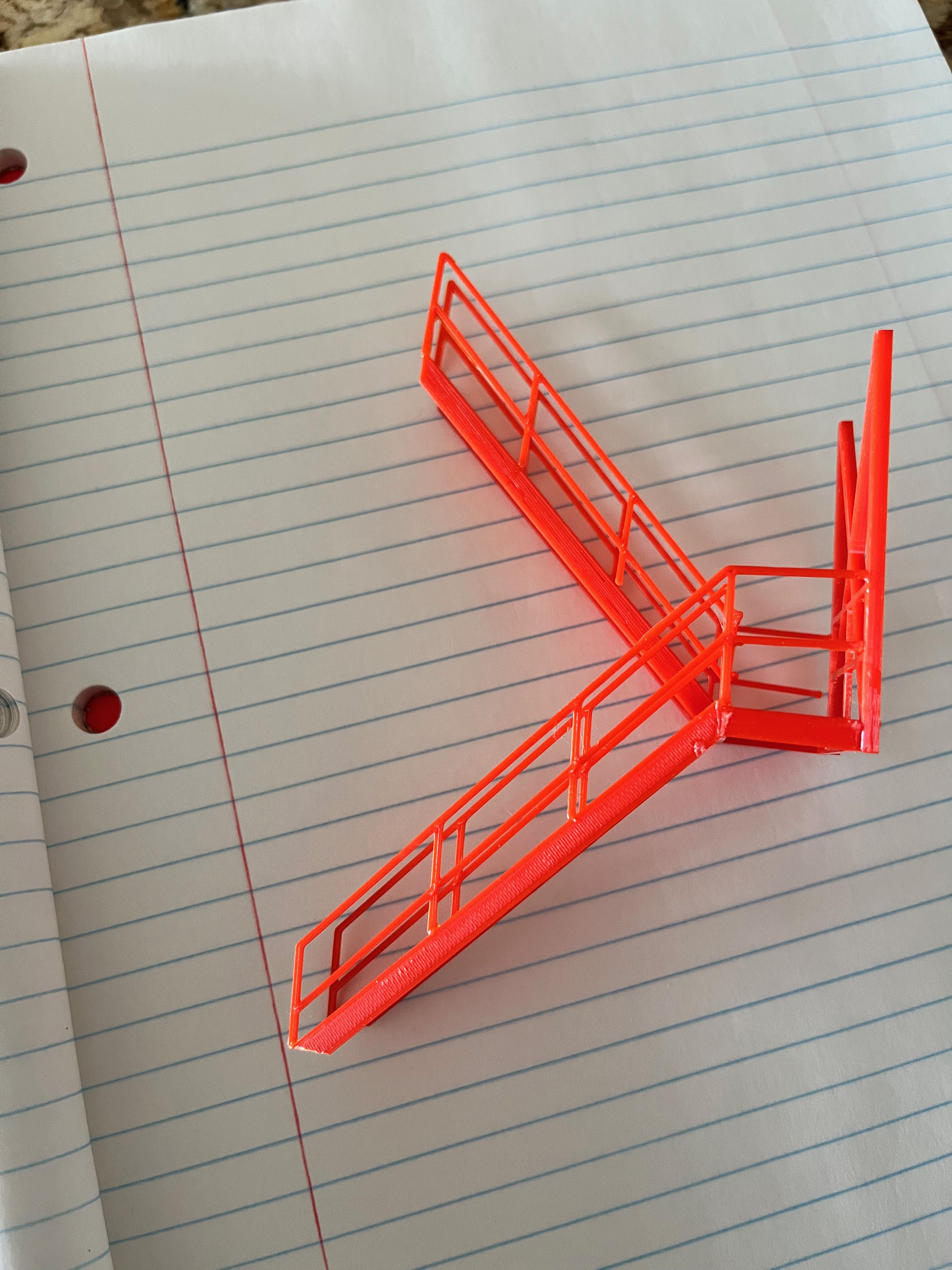
The easy parts have been redrawn; elevator, stairs and floor structure. Now I am working on the lower legs that are angled in two directions. I went ahead and printed the lower part of the elevator. The picture shows that even though the correctly sized elevator is only 12.1mm longer, the resulting elevator structure will be noticeably more substantial in size. Also notice that the elevator doors were incorrect per 75M-05120. This is more work than I originally planned, but in the end I think it will be worth it.
As I rebuild the tower I look at how to best draw and print pieces. Much of the tower is built using I-beams. If you print an I-beam as one piece you will need to add supports. Most people seem to create two pieces that are glued together. The farscape1 model slices the I-beams two ways. The floor supports divide the I-beams in the middle of the webbing. This is a rather visible portion of the beam that needs to be meticulously matched up in multiple directions. Since these I-beams are covered by flooring it is not too noticeable in the final model. The following picture shows a good joint and a not so good joint.
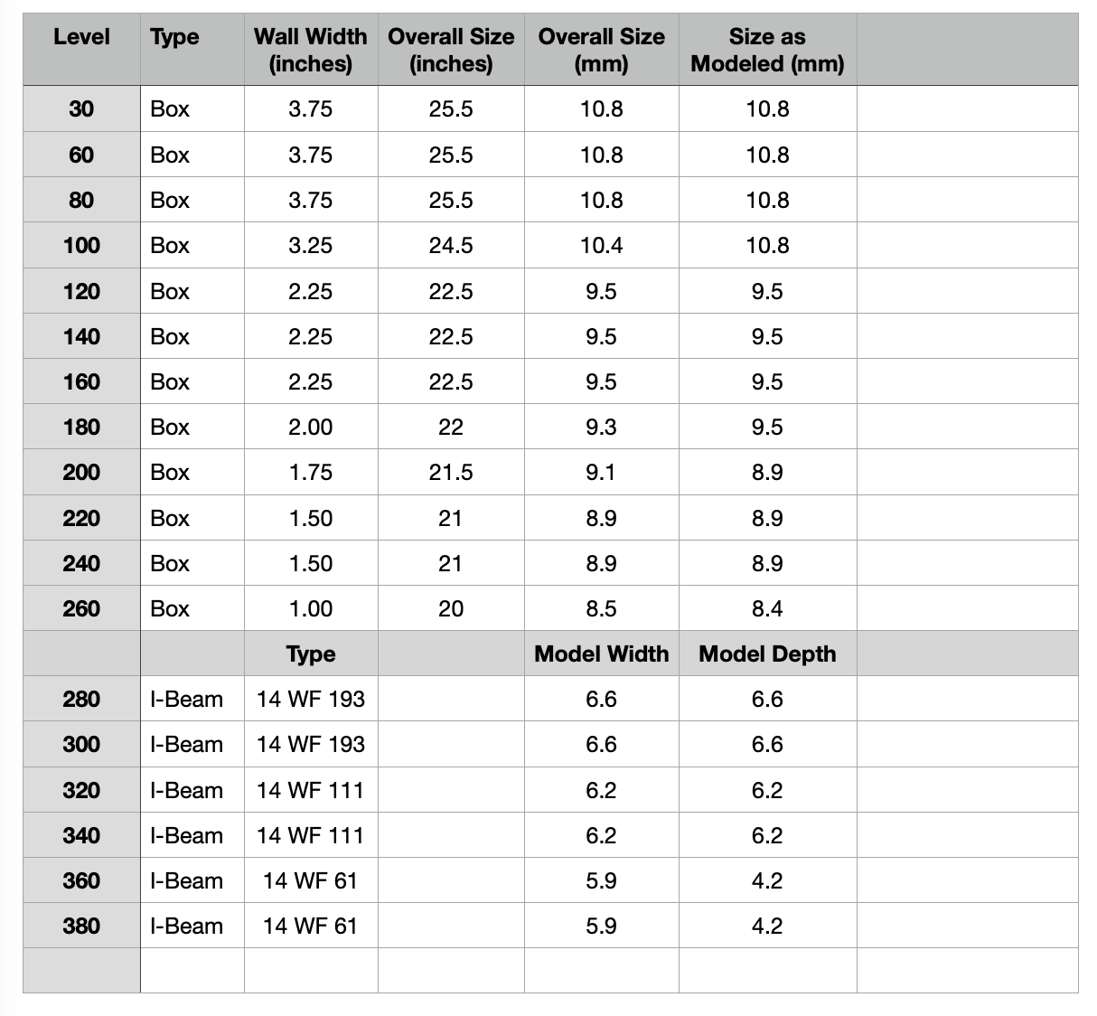
Not all I-beams are created equal. When building a model wooden ship the masts, spars and rigging get smaller as you go up in height. The same is true of the umbilical tower. The I-beams get smaller as you go up in height. This is a subtle but important detail to get the look of the tower correct and not have it look too top heavy. The following table contains the I-beam sizes I gleaned from 75M-05120. In the second table I translated each beam size into width and height for actual and 1:60 scale dimensions. At scale there are some sizes that are close enough that I combined some sizes. I decided to round up/down some sizes to something more printer friendly in some cases. When making the floor beam structure I also decided to make the internal beams that are covered by the floor grating rectangular versus "I" shaped, similar to what the farscape1 model does. All exterior or visible I-beams will be "I" shaped. Note: I made all web thicknesses 1mm even though the actual dimensions should be thiner, I wanted some added strength here. Same for the flange thickness, all are 1.4mm.
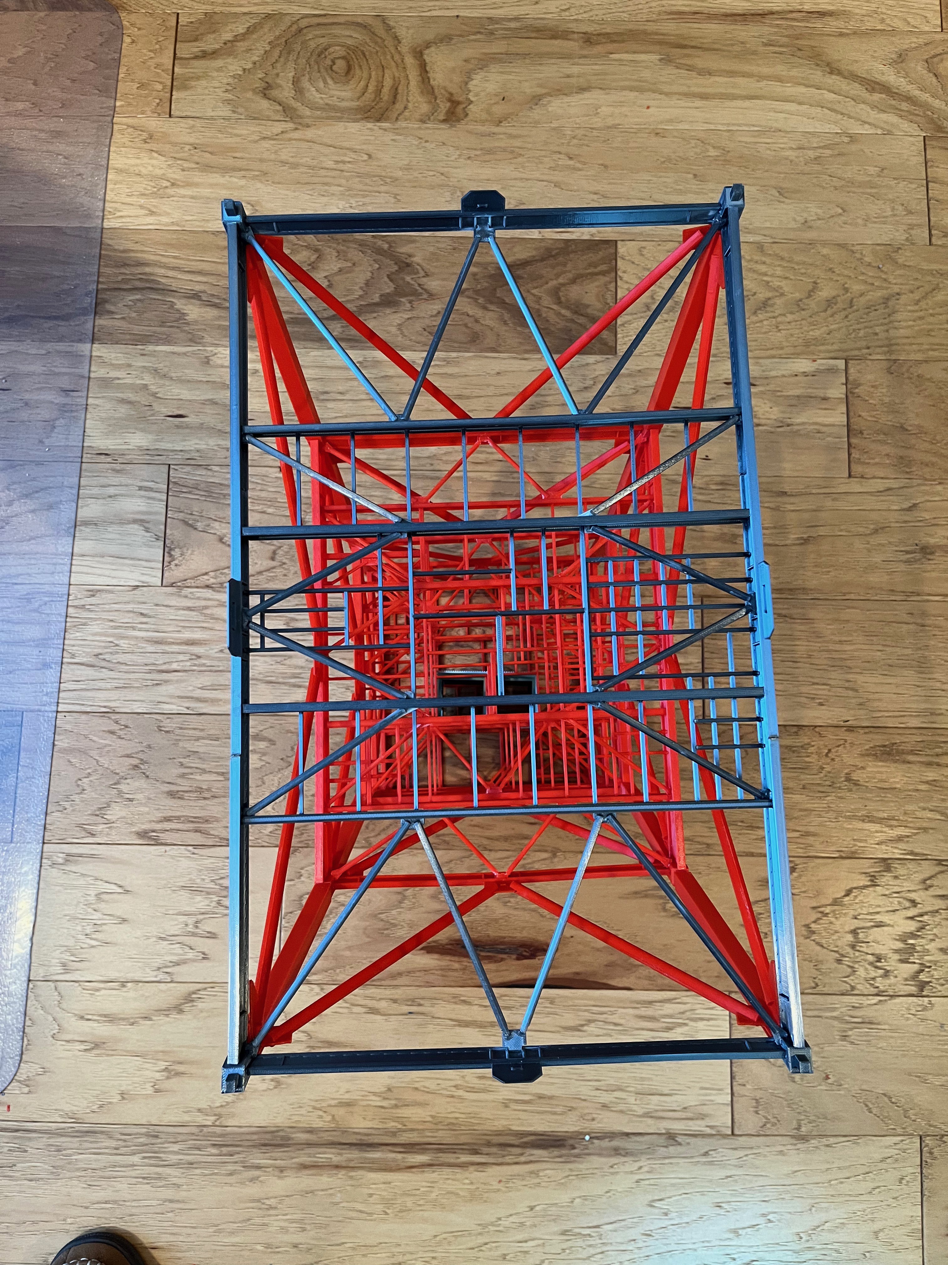
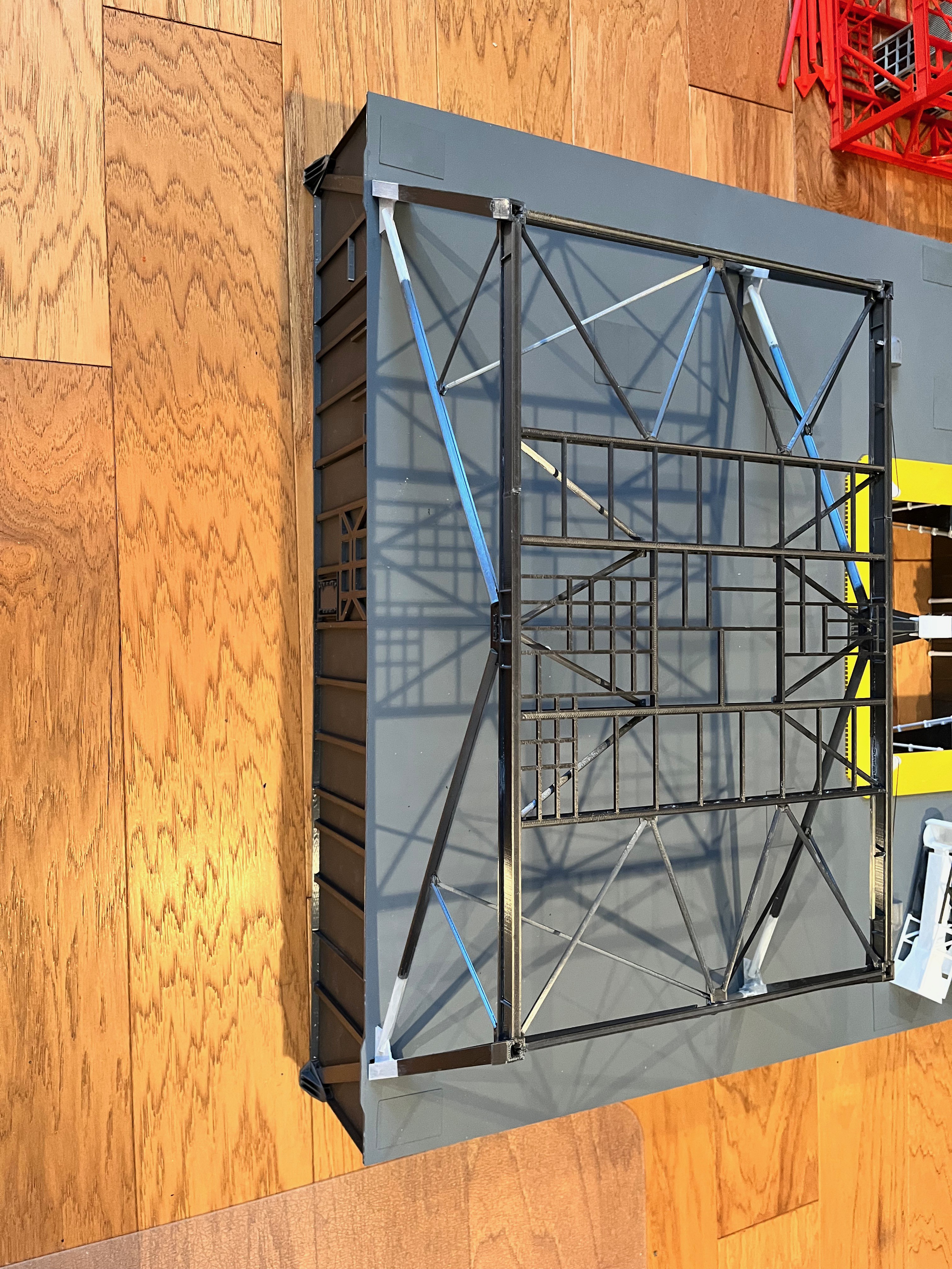
Both sides of the farscape1 floors are flat. Only the upper floor surface should be flat. The lower side has beams with many different heights. After constructing the Level 30 floor using actual sizes I compared the results to the Micro Artwork floor beams. I am pleased with the results. The four major cross beams will have flange strips glued to them. The outside beams are separate pieces.
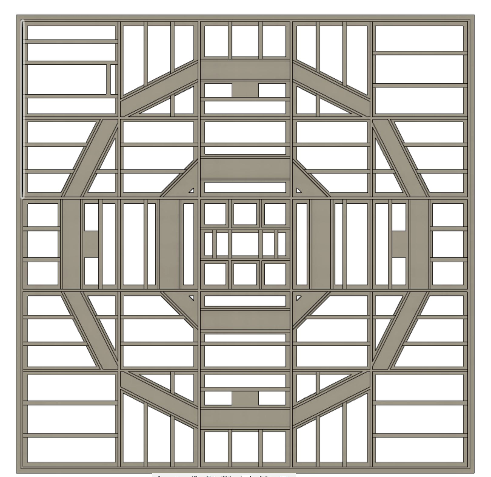
The floor size for all but the first two floors are 40' x 40' so that stays the same. The difference is the size of the floor beams get smaller as you go up along with the column sizes. I have just completed the Level 80 floor beams. The rest of the floors consist of minor modifications to beam and column size. There will be a total of 10 unique floor parts, see attached spreadsheet.Notice that I chose to build the floors from 80 up as one piece, including the corners. Well, not entirely true. There are 6 beams that need bottom flange pieces glued onto them, the four perimeter beams and the two large inner cross beams. All the other beams are rectangular shaped and not "I" shaped.
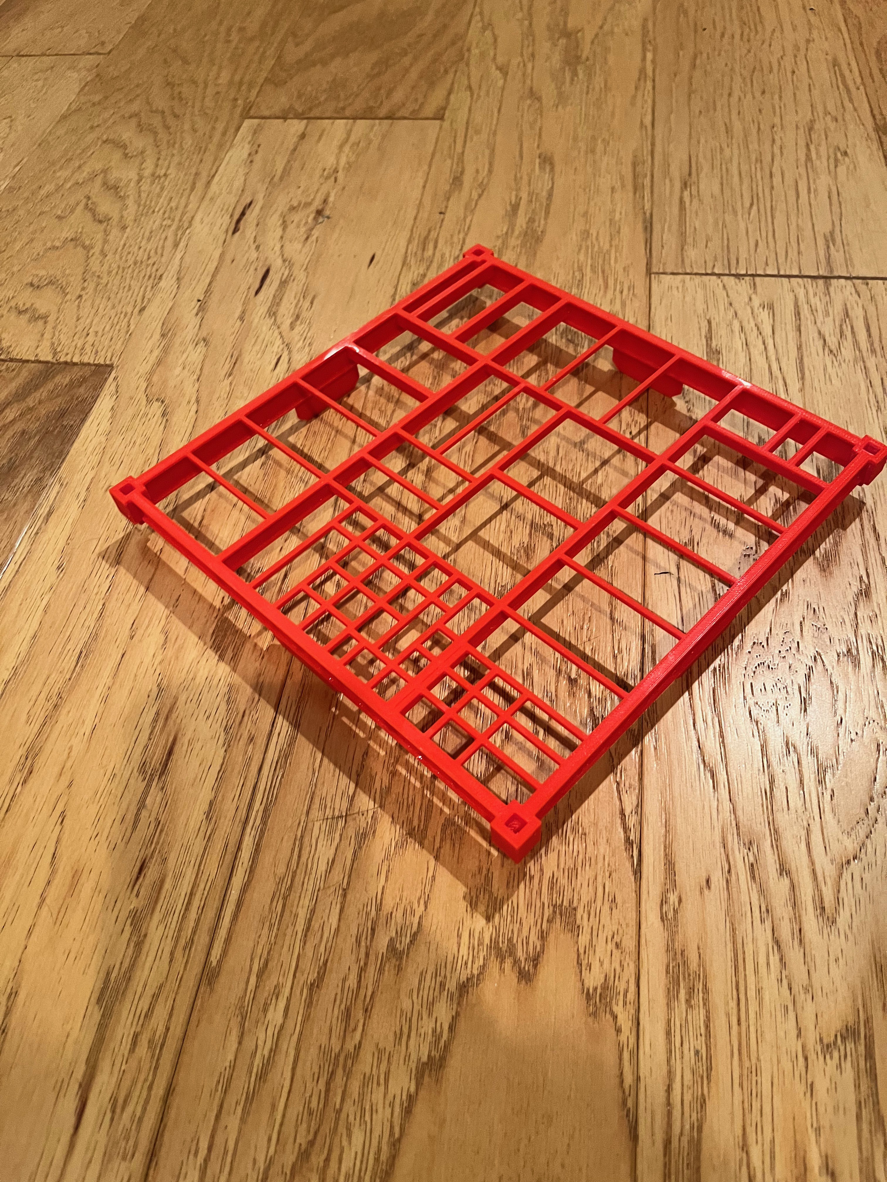
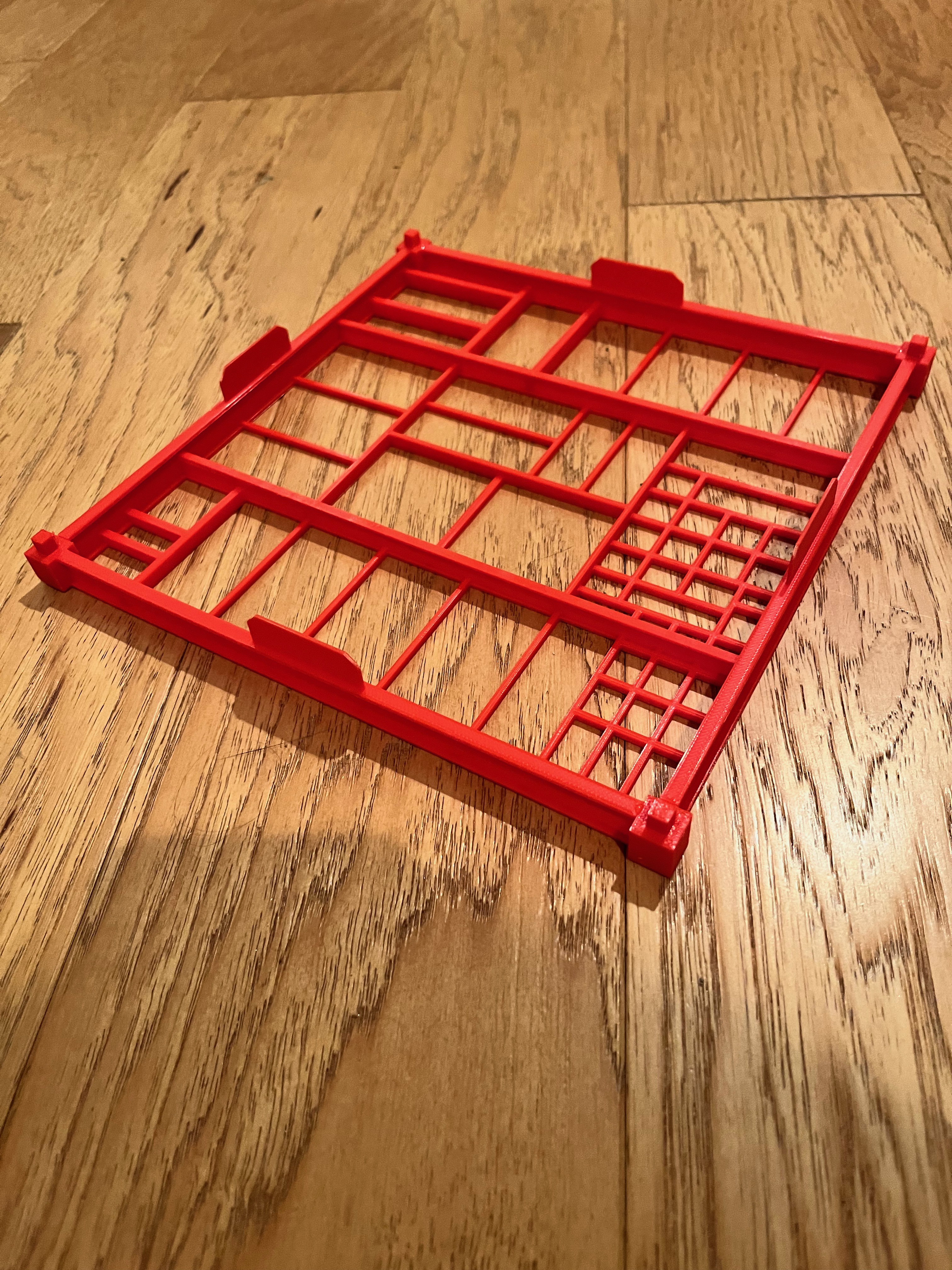
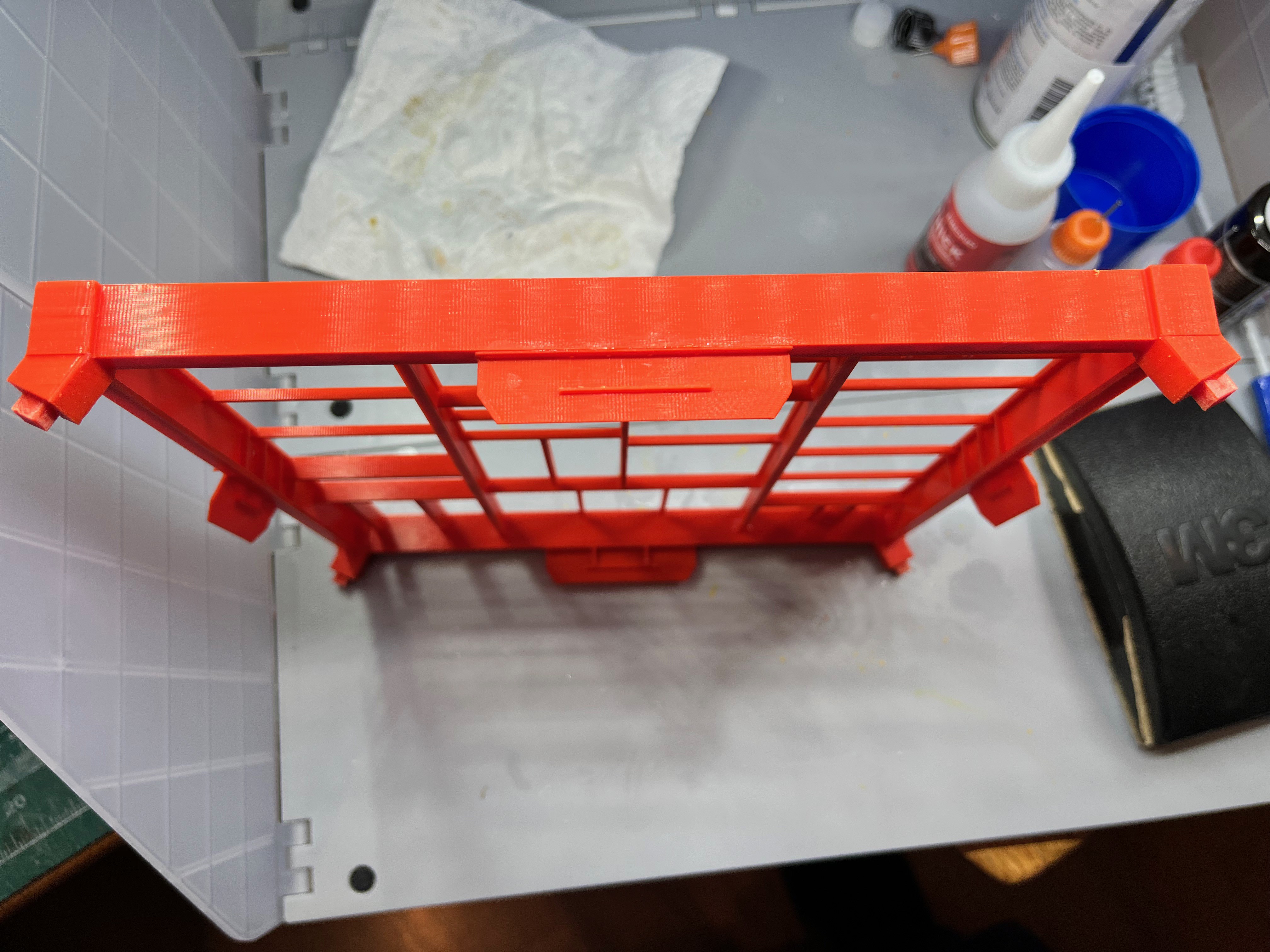
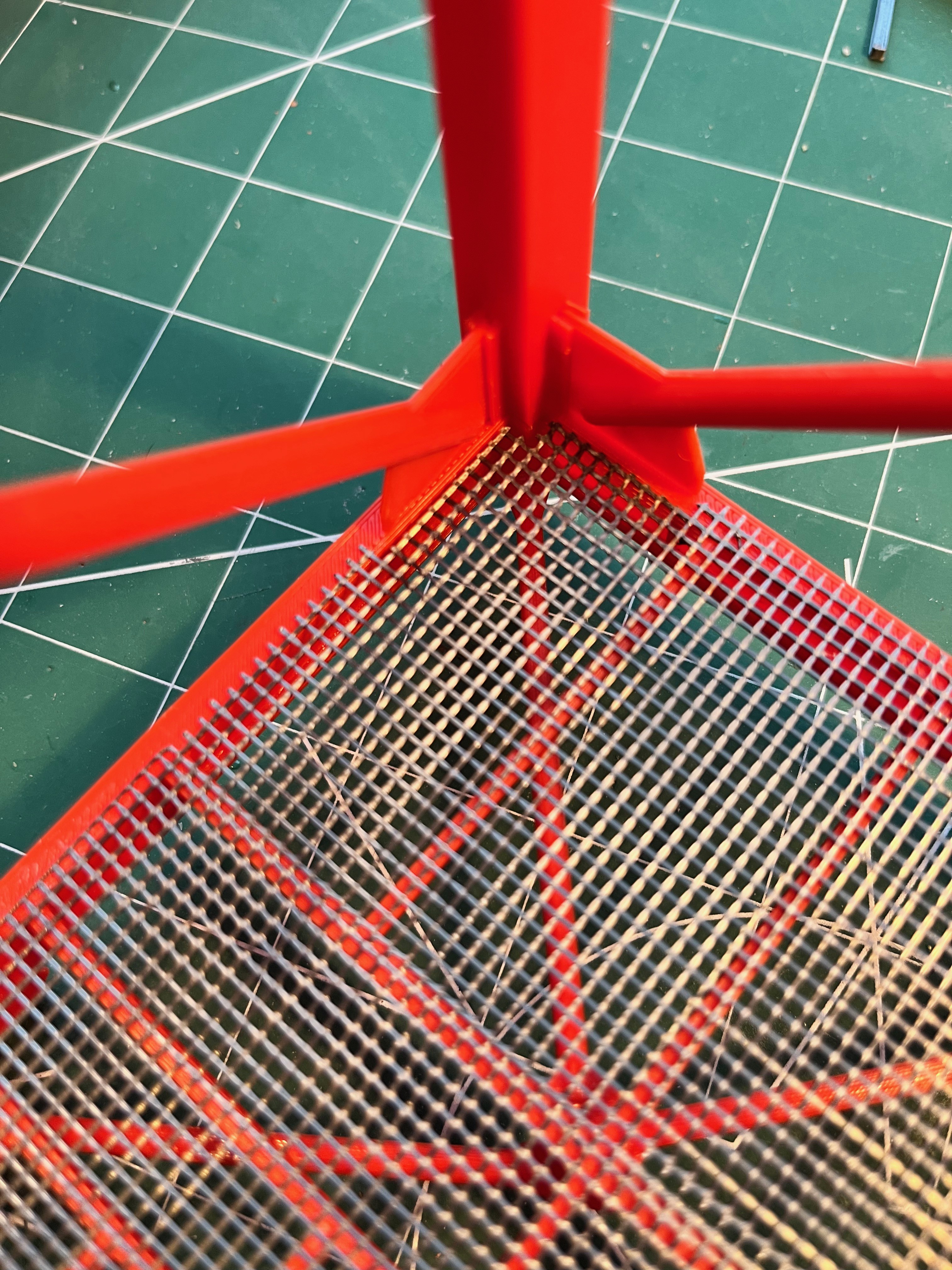
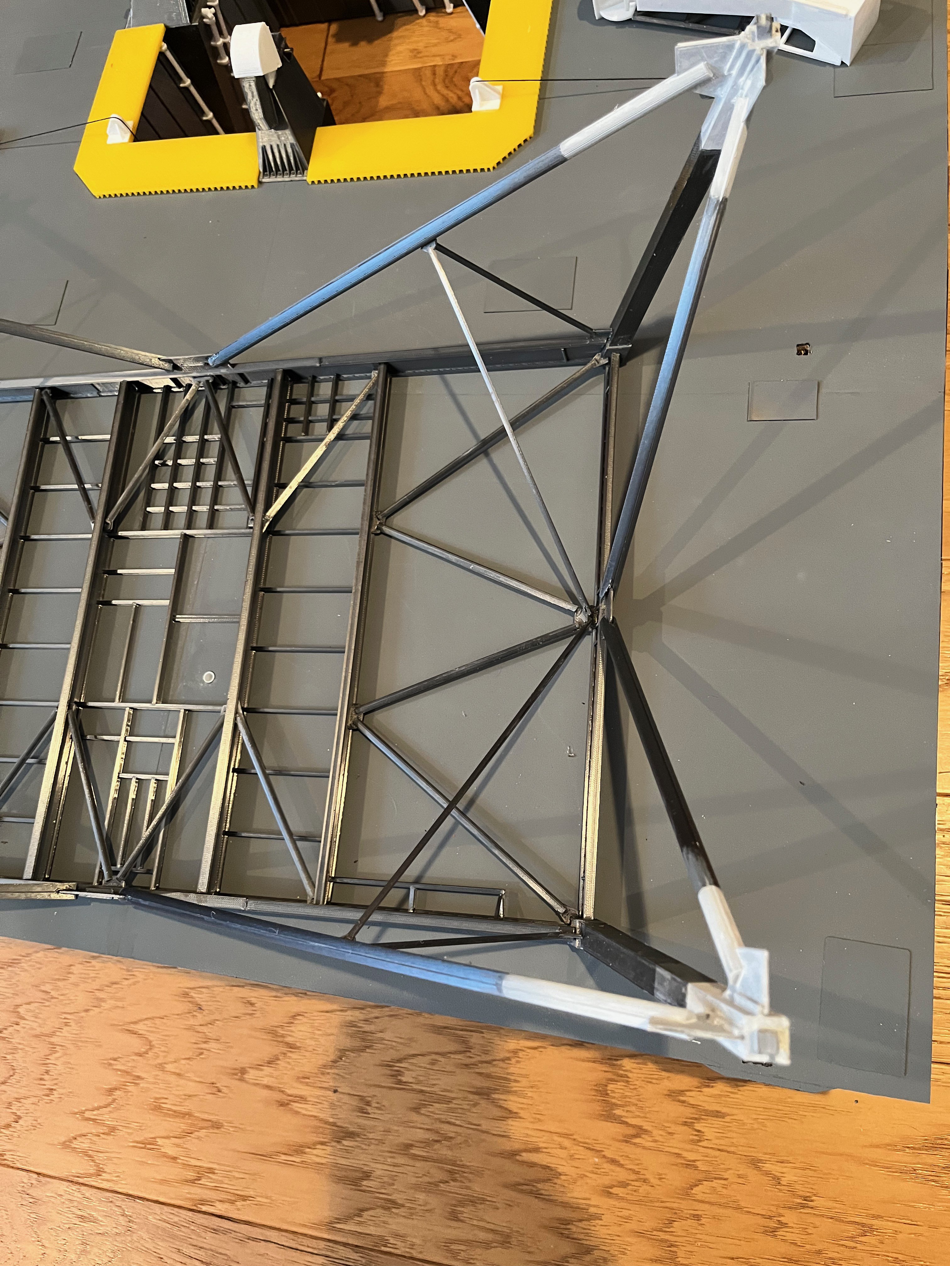
Now with all but the Level 360 floor drawn up I went ahead and printed the Level 100 floor to see if things are going as planned. I am happy with the results so far. Notice that the I-beams are correctly positioned and proportioned. You will also be hard pressed to find any glue lines. The majority of this structure is printed as one piece. This adds strength and dimensional stability. There are six I-beams that are modeled as actual I-beams, the four perimeter beams and the two largest internal cross beams. These six beams have their bottom flange printed separately and glued on, making the glue joint hardly visible. For the perimeter beams I chose to print the main brace gussets as part of the bottom flange. This corrects many deficiencies of the farscape1 model. The gussets are correctly sized, there are no glue lines and the gussets are centered without any glue tab behind them. The other advantage is when assembling the floors. The upper end of the braces will have a slot that fits over the gusset. This allows for some adjustment of the length of the brace. My plan is to glue on the legs and then the bottom of the braces to the legs. The floor can then be added to the structure and once the floor is squared up a small amount of thin CA can be used to cement the top of the brace to the gusset, no glue joint visible. I did forget to add beam stiffeners to the perimeter beams where the gussets attach. I will add those as they are visible detail that enhances the model.
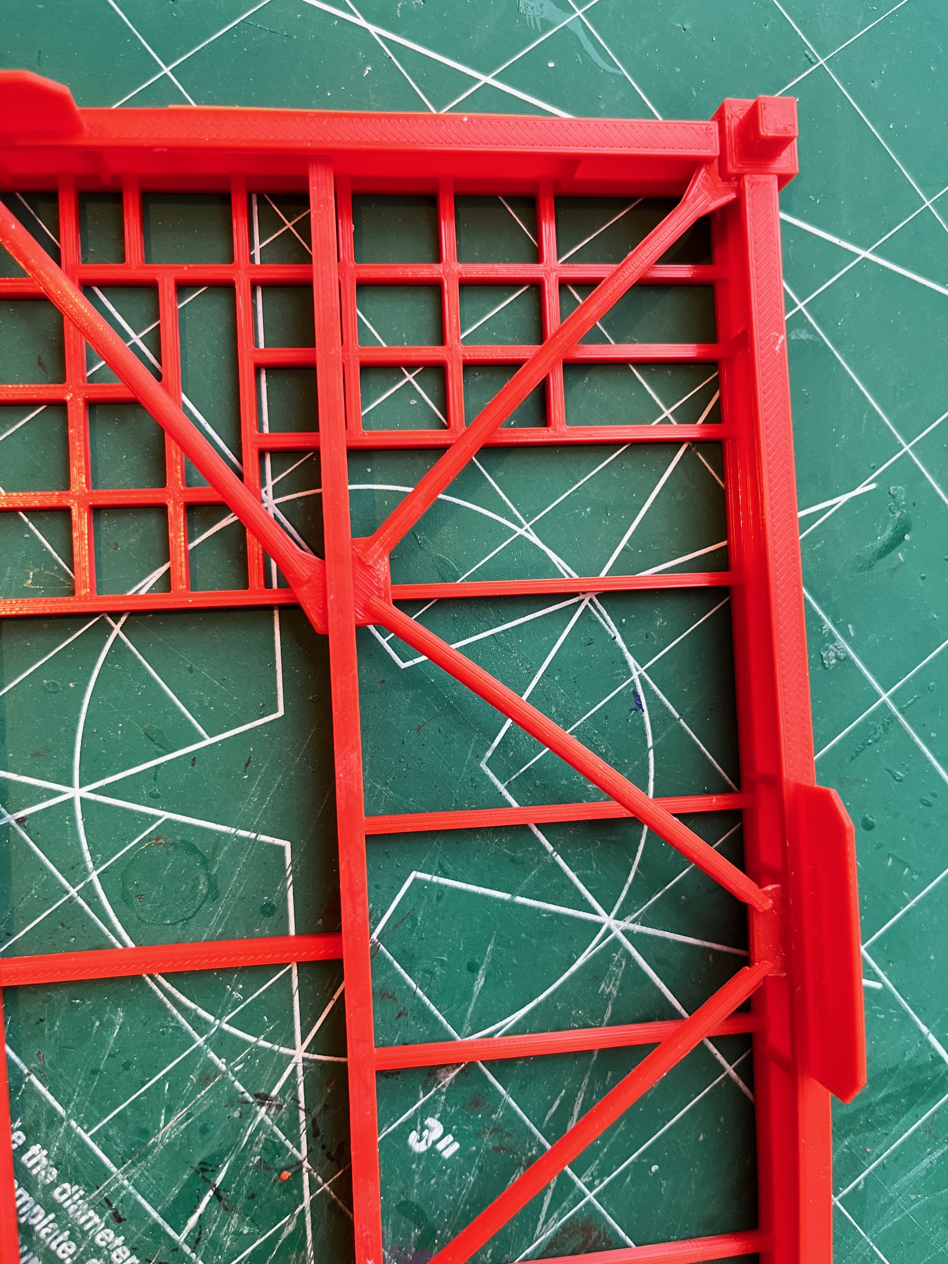
The Level 100 floor is complete. You can see the lower beams under the I-Beams. Notice in the one corner there is added support for the gantry arms. The farscape1 model has the main vertical cross braces glued to a glue tab on the leg. On page 57 of 75M-05120 you can see that there are two tabs welded to the legs that sandwich the gusset and the whole thing is through bolted. The advantage of two tabs is that this joint can be adjusted slightly with no unsightly gap. On the complete assembly (Level 100 is the top floor) you can see I reprinted the floor to add stiffeners above the gusset per the plans. I even added the stiffener on the center gusset. None of this is glued except for the pieces that make up the floor. Everything is a press fit for now. My plan is to be able to assemble the entire tower and ensure everything is level, straight and true before gluing any of the pieces together. The main vertical cross braces are made to move in multiple directions without noticing any gap or glue joint.
I finished drawing up the Level 380 floor. It was quite a bit of work. I need to set it aside and verify it in a few days. The micro artwork diagram for this floor does not match the 75M-05120 page 77 diagram so I went with the original document.
The more I dig the more I realize how inaccurate the farscape1 model really is. I just realized the legs not only get smaller as you go up but at Level 280 they switch from a box to an I-Beam profile. Here is the Level 280 leg. Now it's back to the CAD drawing board to redraw the legs from here on up and modify the floors.
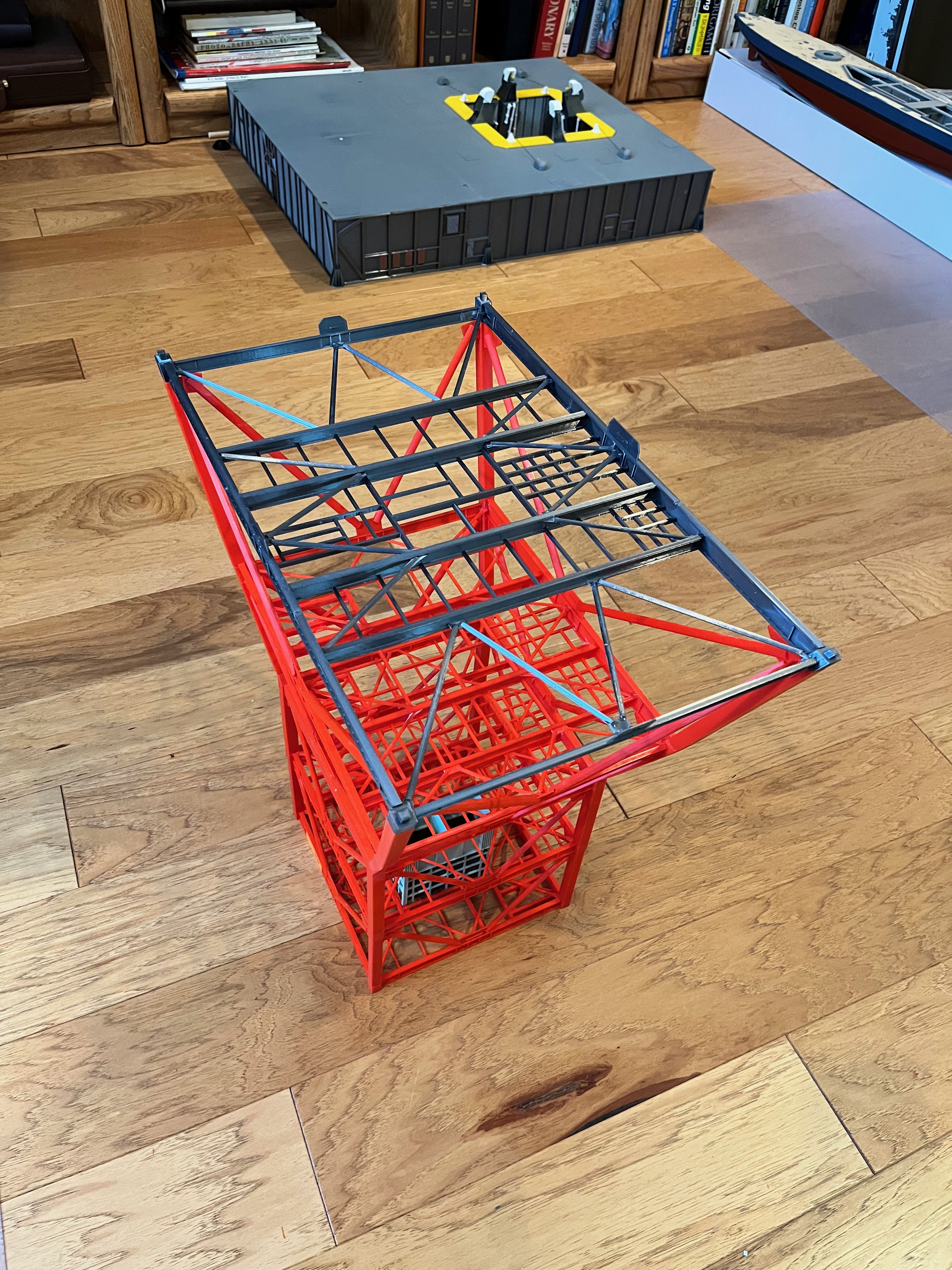
Here are levels 80, 100 & 120 dry stacked. I'm pleased with the results so far, although I just noticed some stiffeners are missing on level 80. I will add them to the drawing but probably not re-print floor 80. I will just print some strips and glue them in. I feel confident about the level structure from here on up. I will now concentrate on finishing the structure for levels 30 & 60.
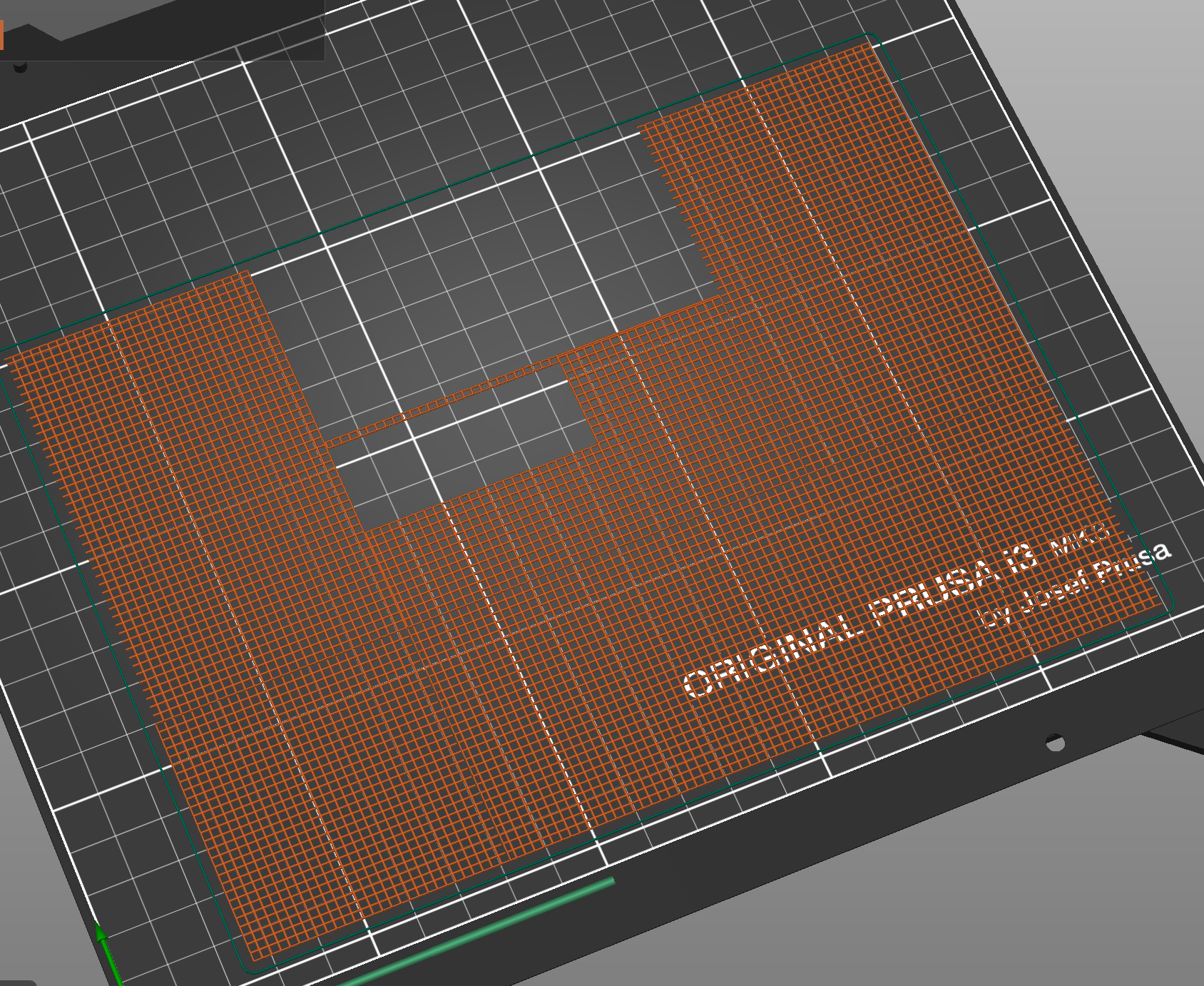
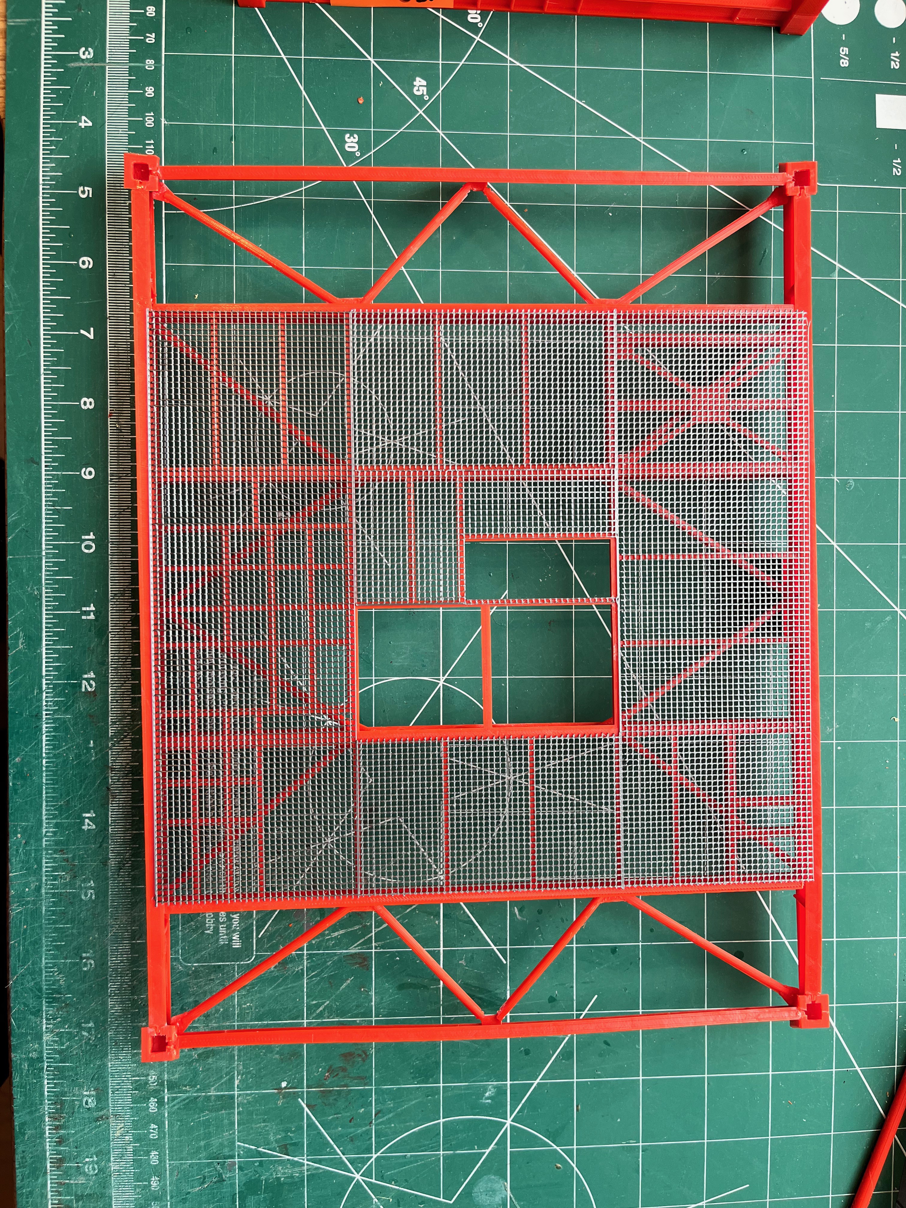
The floor grating pushed my old laptop to its limits. I had to create the floors in 9 sections, 4 unique pieces. They lay out as follows:3 2 34 1 43 2 3A first test print showed the pieces would be hard to line up so to get a single print I first saved them as STL files and then imported those files and joined them together. This created a pretty good print for levels 80 on up. My larger printer could print the first two floors but it has the elephant foot issue so these will get printed on the Prusa. For the lower two floors I will have to print them in parts because the entire floor won't fit. When I publish the floors I will include the separate pieces and the joined pieces I am using. If you want you can join them together or in a different way.
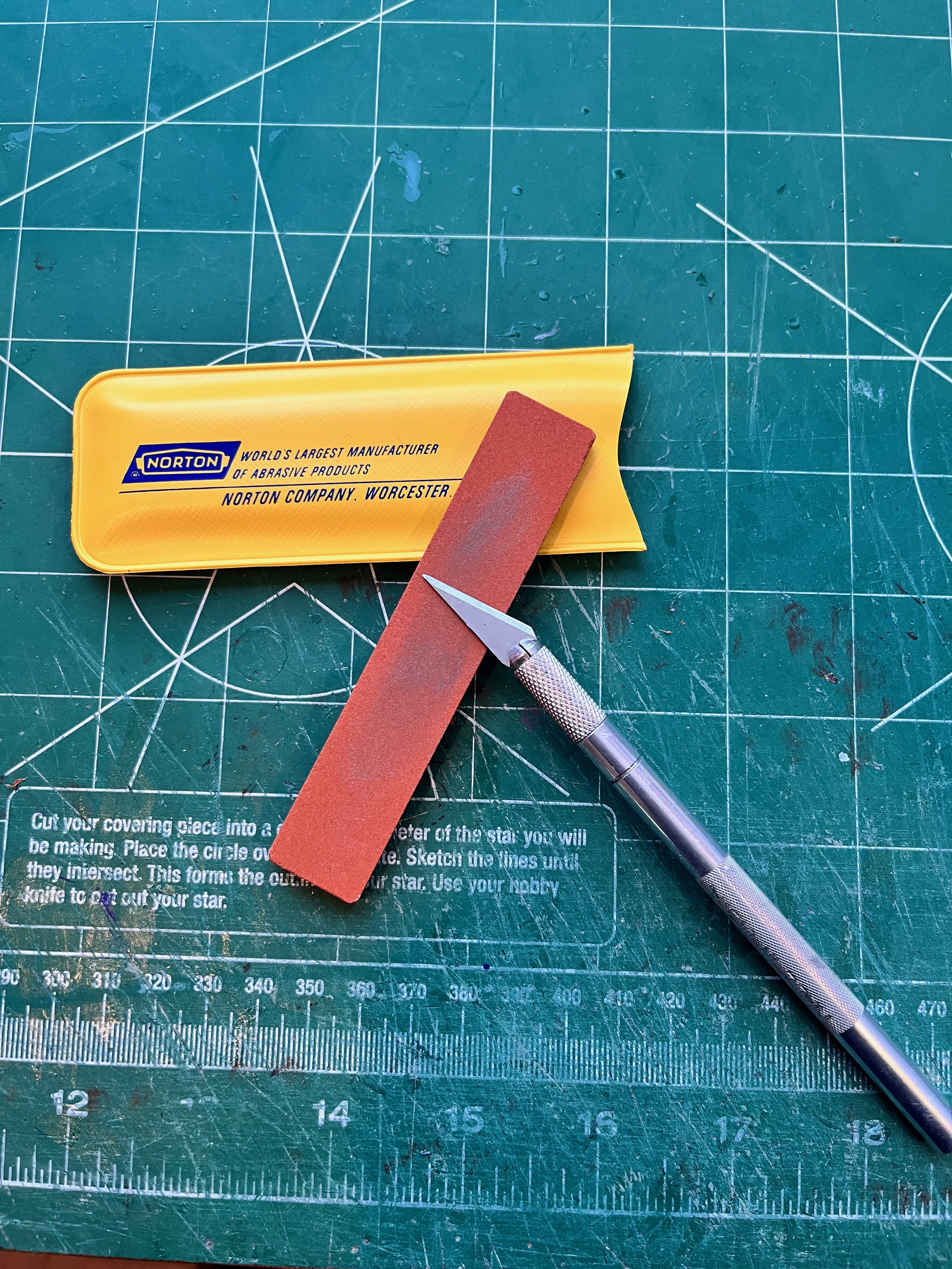
Since the vertical columns get skinnier as you go up the tower, that means other parts become unique. I could either choose to create unique parts or print generic parts and use an exact knife to cut the parts down to size. I'm talking about the floor grating and the 6" corner braces. These parts are not very visible and easy to cut so I chose to sharpen the exact knife instead of sharpening my Fusion 360 skills.
Here are levels 30 to 120 upside down, dry stacked. I am feeling pretty good about the structural portion of the tower. The elevators and floor grating are drawn up and print verified. I have drawn up the stairs and will work on printing and gluing up the stairs to verify the drawings. After that I will publish those three pieces of the puzzle.
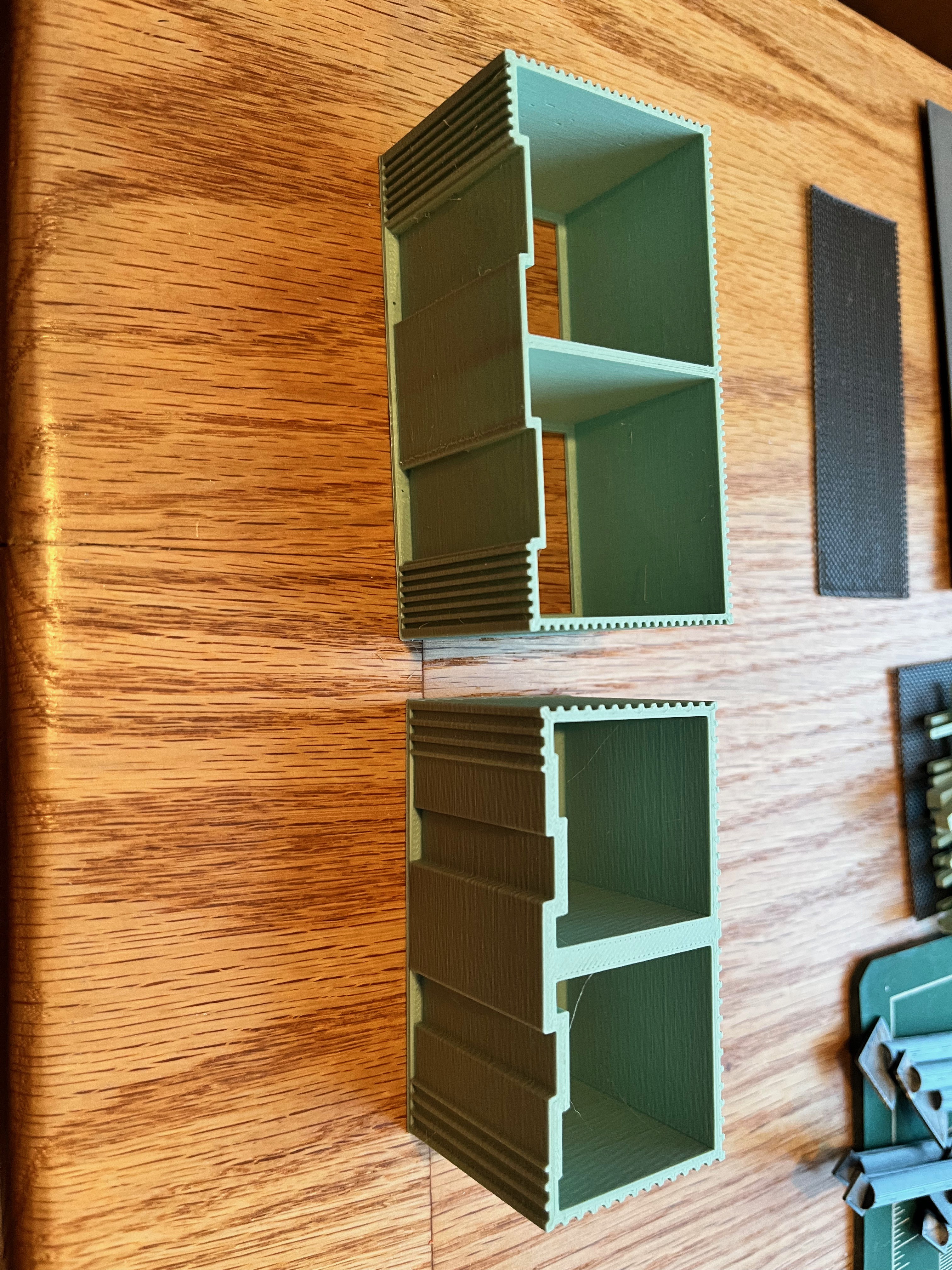
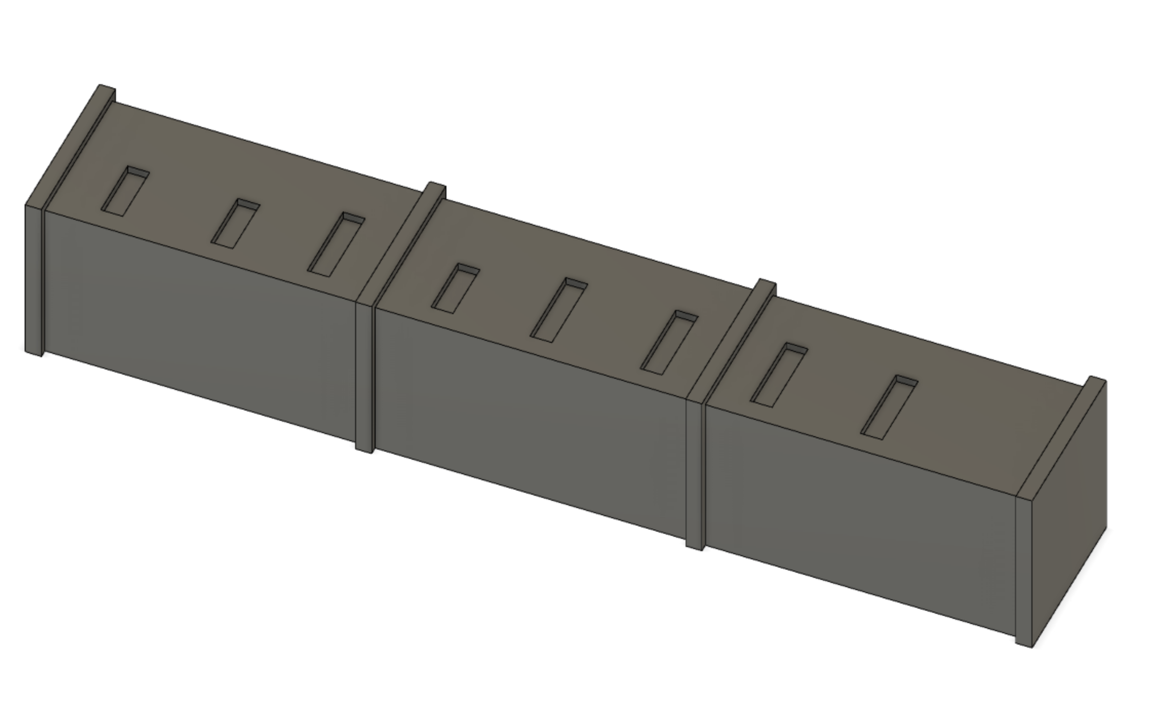
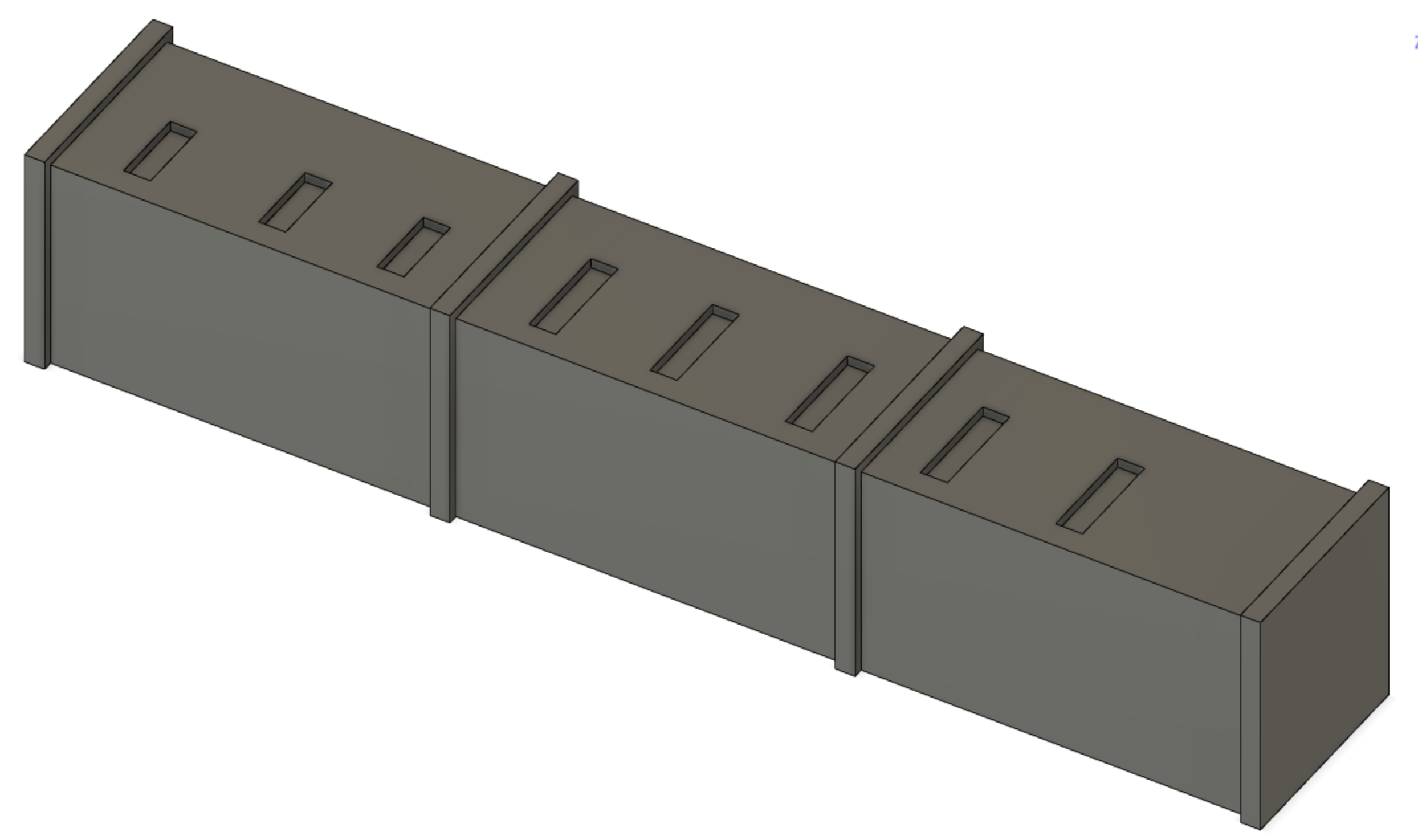
Looking at the Level 0 additional parts. My plan is to use as many of Aviator67 parts as possible. Comparing the 3 cable enclosures to the drawing 75M-05121-137, the length/width/height looks good. My thought was it would be nice to have indentions for the cable trays to sit in, easier to glue. I then compared them to the MicroArtwork and realized these parts match the MicroArtwork diagrams and not the actual engineering drawing. The difference is the number of bands around the boxes. The engineering drawing shows four bands, one at each end and two in the middle. The bands on the large enclosures being 8' apart. OK, so it's time to re-design new parts. Here are the three unique parts in the CAD tool; Inner, Center and Outer.
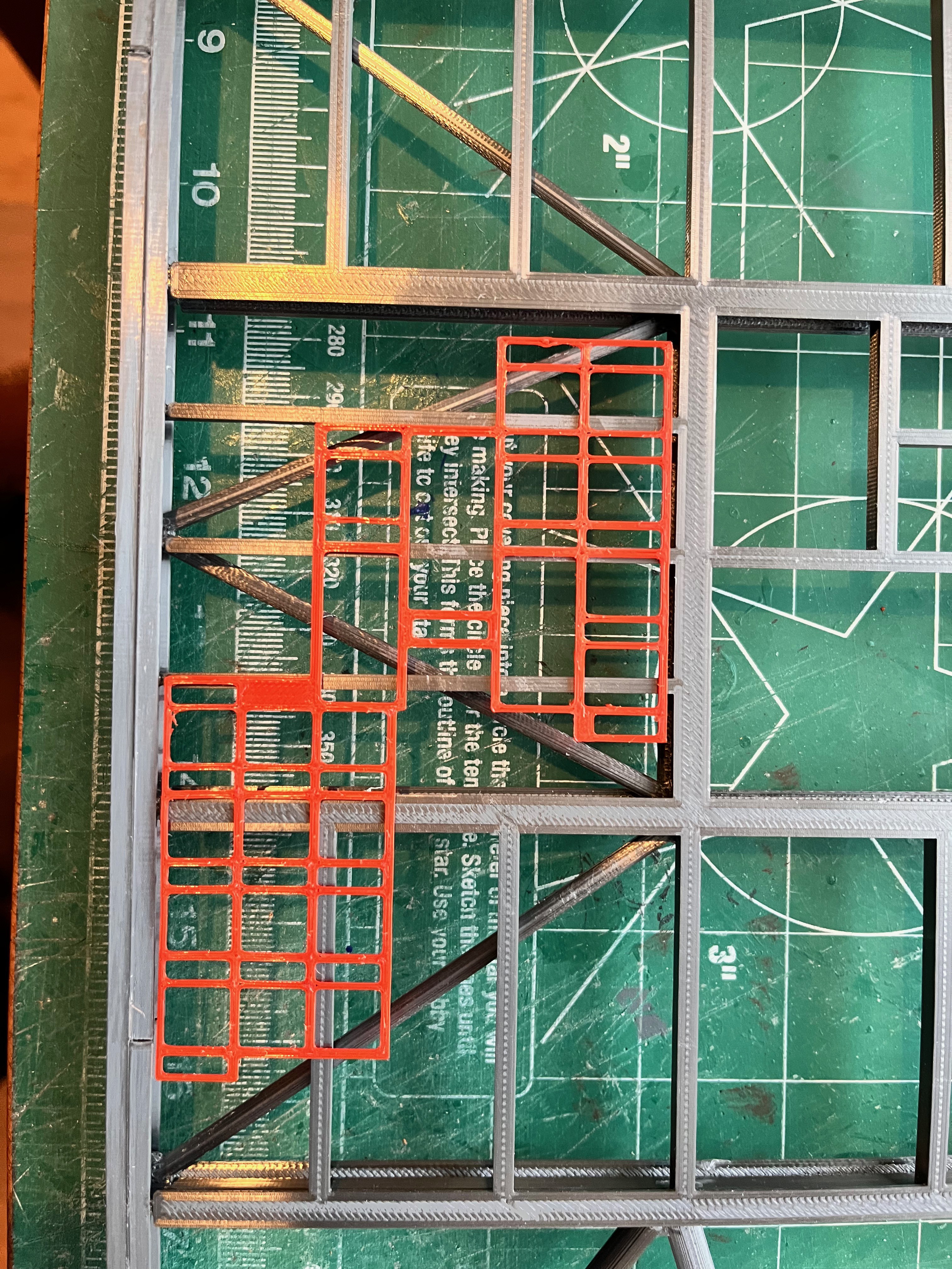
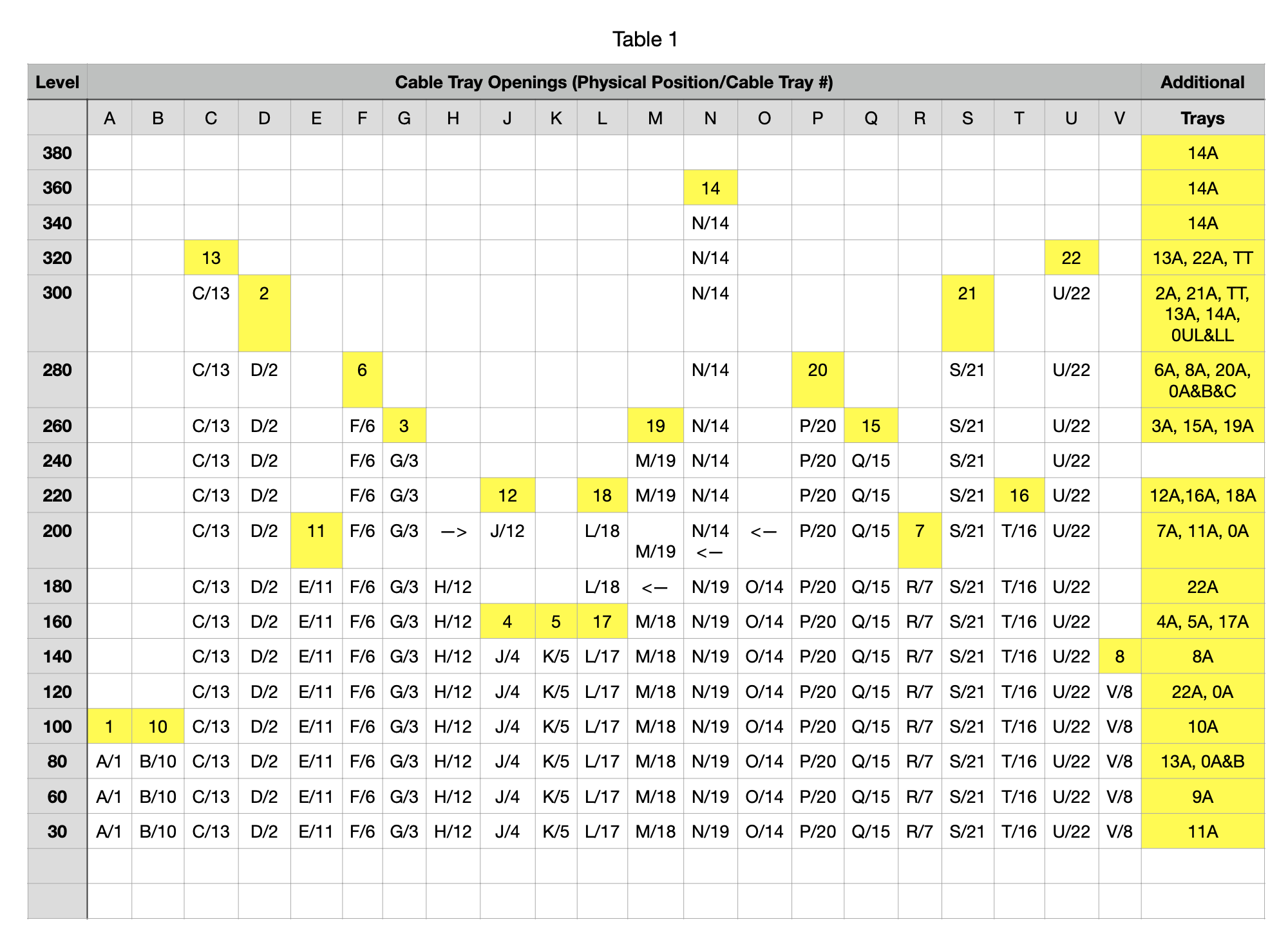
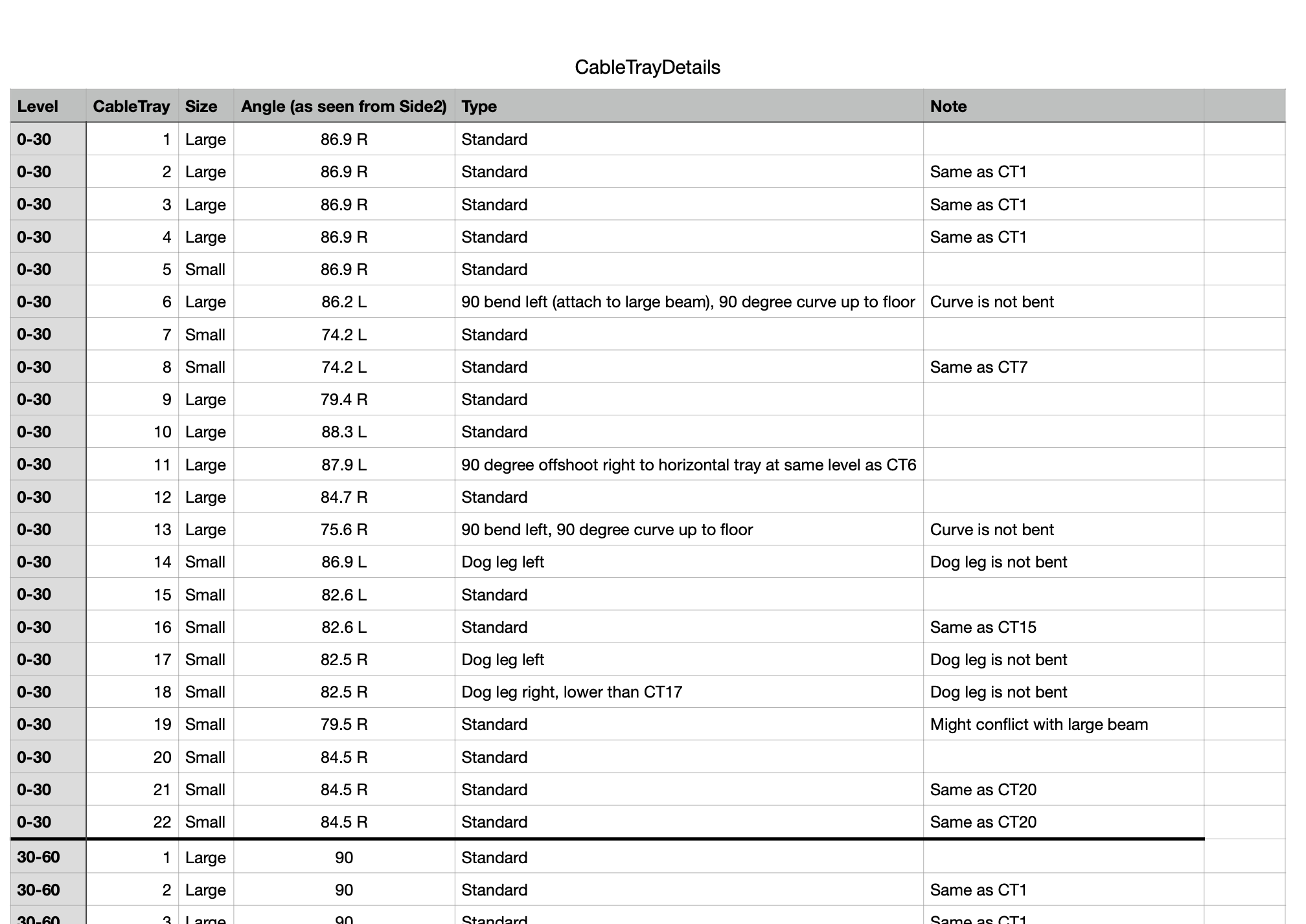
The vertical cable trays are rather complex and cannot be re-used because of the changes to the structure. As I usually do, I am creating a spreadsheet to understand each cable tray before I dive into Fusion. The first thing I did was compare the cable enclosures to the cable tray holes in Level 30 per 75M-05121-137. Measuring from elevator shaft and given a height of 30 feet minus the height of the cable enclosures, I was able to calculate the angle to the right or left looking at the tower from Side 2. Fortunately all the cable trays are 90 degrees looking from sides 1/3. The real cable trays penetrate the floor grating and there is a joint about a foot above the grating. Given the previous test prints of the grating, I realized I would not print holes in the grating and have the cable trays joint at the grating. Here is a snapshot of the first level of vertical cable trays. There has been some inconsistency between the official documentation and MicroArt as to which level the cable trays belong. I chose to unambiguously label them Level 0-30 for the cable trays that exist between Level 0 and Level 30. Here is a screen shot of the first part of a rather long table. You can get the complete table on Printables.
Status Update: I have completed the initial drawings of all the cable tray parts, 89 new parts. There are two new/updated spreadsheets in the main LUT model that help understand the cable trays. I have also updated the LUTPartsList spreadsheet to show my progress. I am now 24 shy of 3000 pieces that have to be printed. I'm sure this model will go over 3000 when I start on the gantry arms. Now that the cable trays are out of the way, I will test out under floor lights and then I should be ready to build out Level 0-30. After that I will probably publish the elevator/stair parts and the cable tray parts, knowing that only the parts I have printed and glued up have been verified.
I now have the railing design completed. The first thing I noticed was what I am calling catwalks on Level 30 that extend out and have three cameras each. Aviator67 has the camera and camera mounts so I will use those as is.
Yes, I have noticed many discrepancies. I'm guessing this may be due to modifications/additions that were made between missions. If I find a discrepancy, I am considering the 75M-05120 and 75M-05121 documents as the absolute truth. They win out over everything else. For the cable trays there are plenty of exact measurements. I do like the Micro-Artwork because it is easy to visualize the parts in three dimensions.
Level 0-30 Structure: The first level structure is complete!
 The other method used is to slice the perimeter beams long ways through the webbing. This leaves a very visible seam along the top and bottom of the flanges. Again, not the best solution.
 What I will do is create two pieces, a flange and a combination of the other flange and the webbing that form a "T" shape. This will place the joint not on a flat surface but at a 90 degree connection point. Combining the two pieces does not have to be exact, just make sure the two pieces are weighed down to form a good flat surface. This is what I did with the crawler and it worked well.


Discussions
Become a Hackaday.io Member
Create an account to leave a comment. Already have an account? Log In.