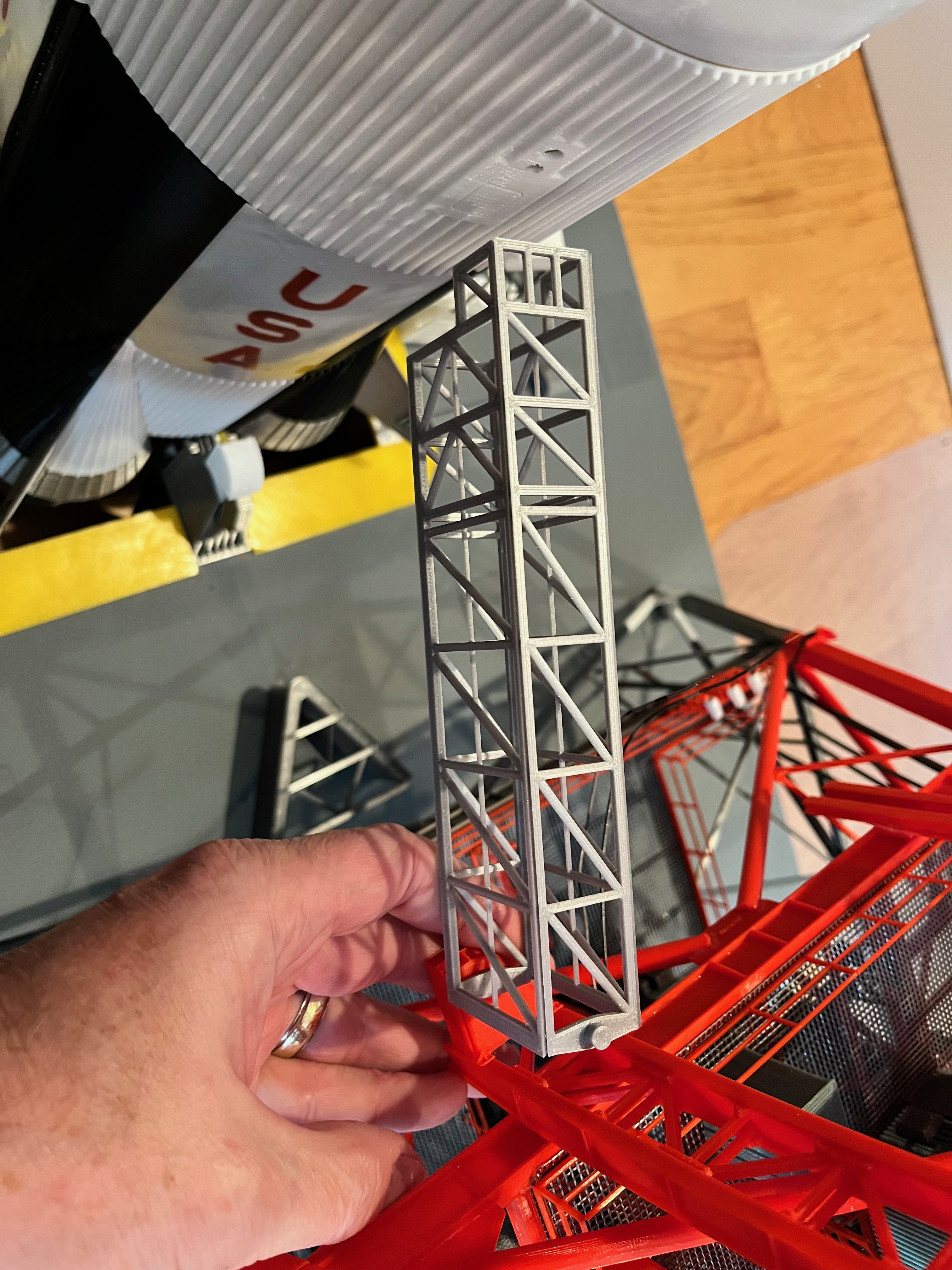
Swing Arm #1: I have started designing the first swing arm. The hinges are already designed and printed. The first thing I did was measure the distance and angle between the hinge pivot point and the connector on the rocket. With a hand held protractor and a 6" ruler I was able to eyeball the angle at 73 degrees +/- 1 degree. The actual measurement should be 72 degrees 13'-36". The length should be 452.02" which translates to 191.36mm. The actual measurement is 188mm which is within 1.75% of the actual measurement. I couldn't be more pleased with the results. The launcher and tower have to be pretty close to exact to get these results. This means I can go with actual measurements and take advantage of the sliding components that bridge the gap.
Here are pictures of a test print of the first and second elements. I used some "Galaxy Silver" filament that shipped with the printer, something I would never use in a model. The cross beams are round and everything else should be angle iron, but like before I squared those off for strength. These arms should be light and airy, not something that looks like it is made from Legos or something out of MineCraft. Lots of bling still needs to be added to these pieces. For the grating I plan to go with something even lighter than the floor grating. I will try a 0.2 x 0.2mm grating that is integral to the sides and bottom.

Swing Arm #1: I'm glad to be doing something more exciting than pipes. The swing arms are detailed models unto themselves. I suggest you get a good pair of tweezers and a lighted magnifying glass on an arm.
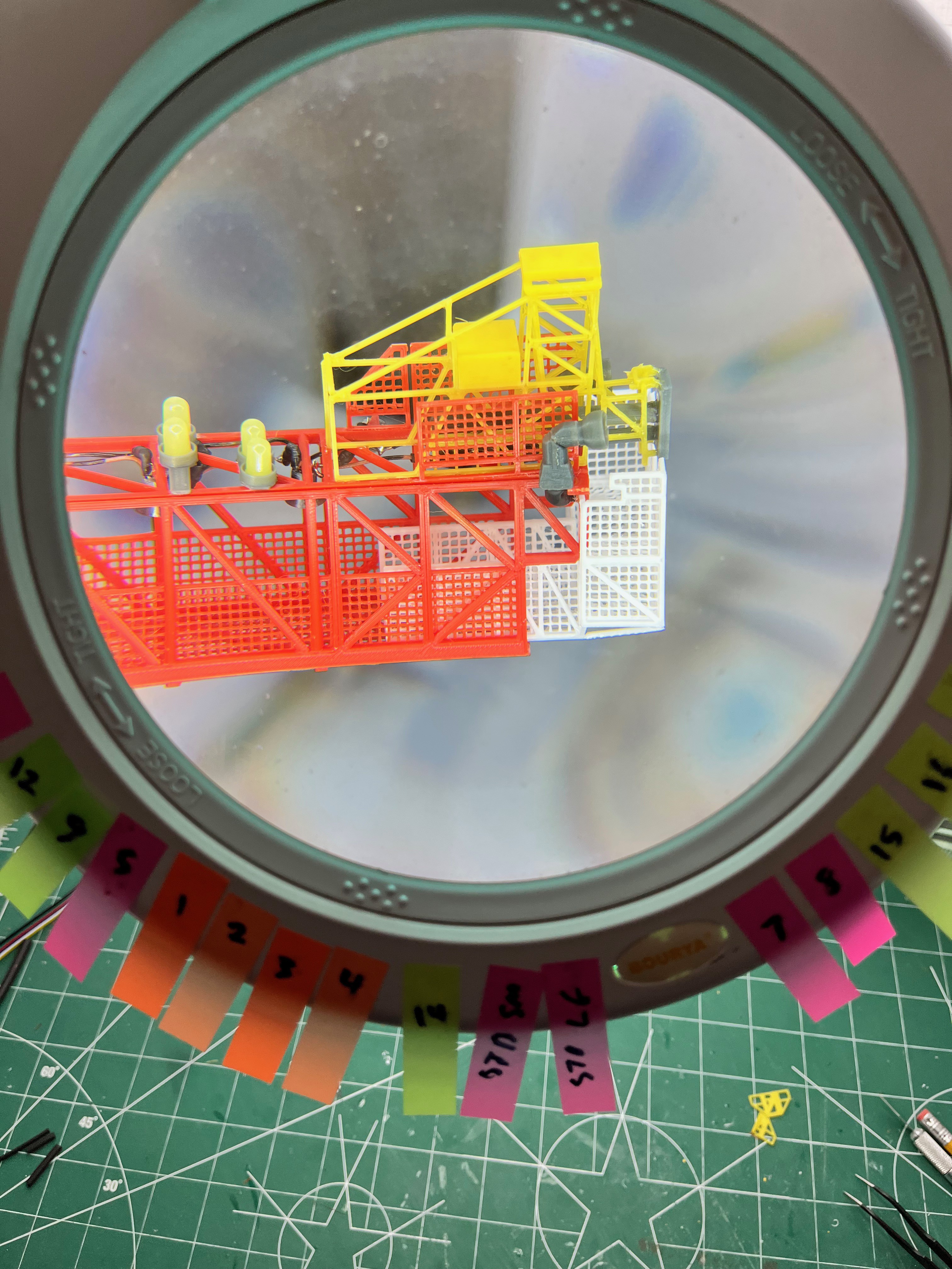
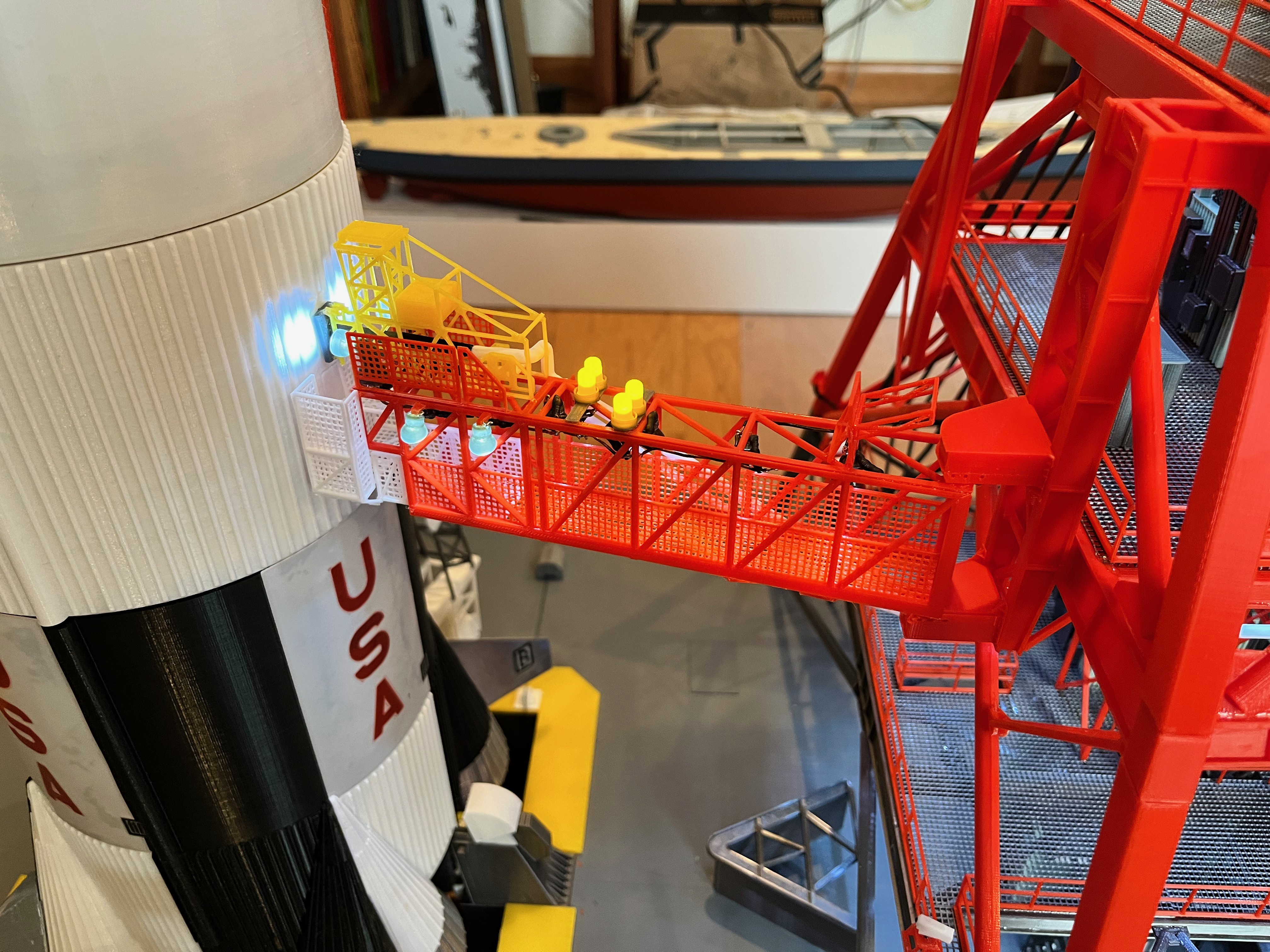
The yellow lights on top of the arm should be 3mm. I had some leftover 5mm LEDs so I used those. They are a bit too large but I had them so I used them. When I publish the parts you will see I made holders for both sizes. The wiring was tricky. The wires for the spotlights needed to be snaked through holes smaller than the lights so I had to solder them in place. Start by gluing the sides to the top, leaving the bottom open so you have access to solder. Once the lights are glued in and working then you can glue the bottom on.
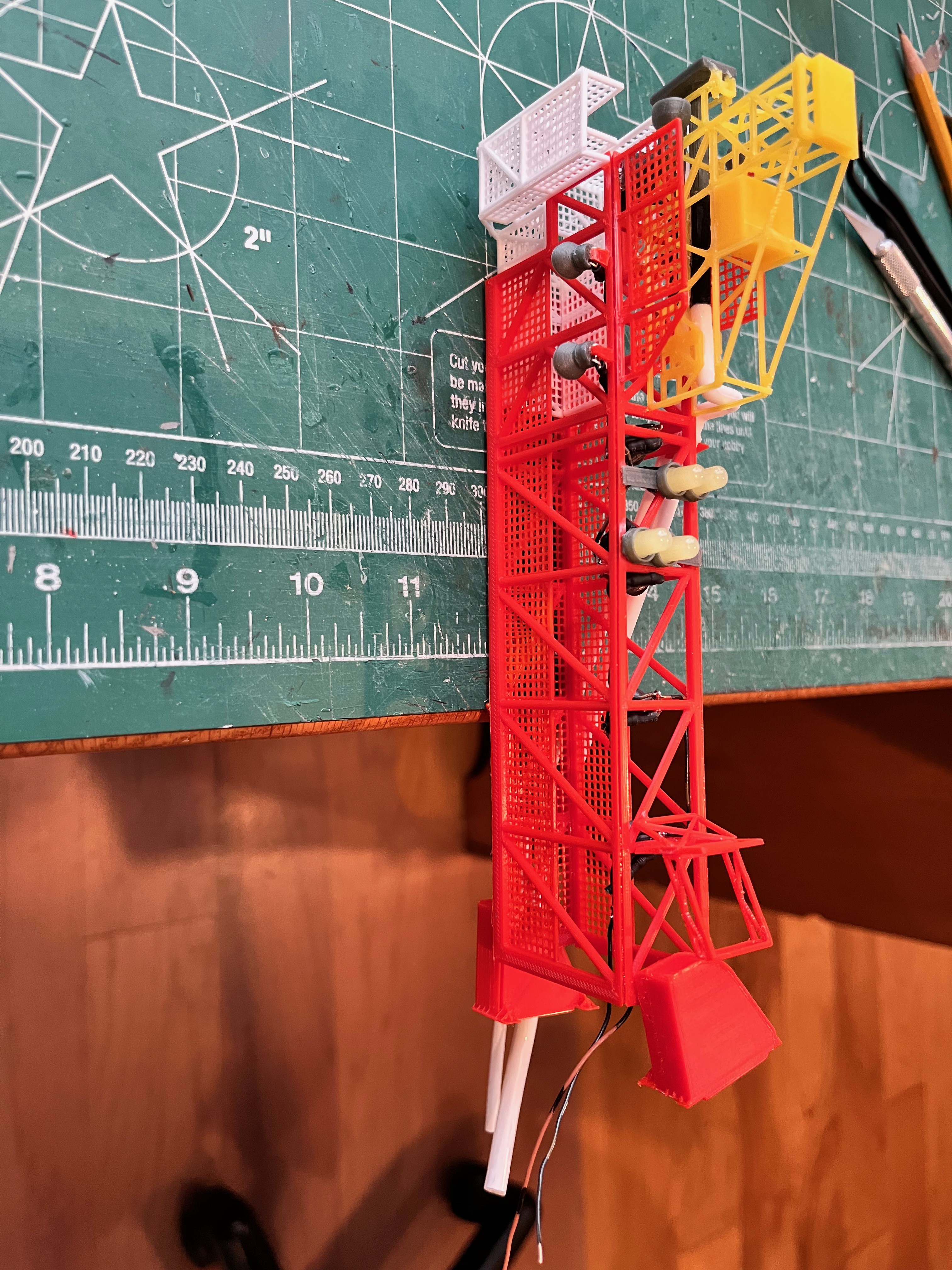

The white extension platform can be left unglued and adjustable. The parts for the swing arm are made to the original dimensions. My arm length is 3mm shorter than it should be. Fortunately this part can be adjusted to make up the error. I chose to glue in the extension platform, leaving a 2-3mm gap between the end of this platform and the rocket. This appears to be to scale and allows a gap for the arm to swing out of the way. On the underside of the platform there are support braces that go out to the corners. I simply cut some 1x1mm braces from a failed print. In the final parts you will notice some 1x1mm straight pieces to use for these braces.
As for the upper yellow structure I am calling the Fueling Mechanism (FM), this part was also made to not be operable. To have made this tiny structure operate would be in the too hard category. As you are gluing up the structure, check and double check with the arm held into place so the end just touches the rocket. I find it best to use slower setting medium or thick CA. Put glue on the surface, hold the part in place with tweezers and then shoot it with aerosol glue accelerator.
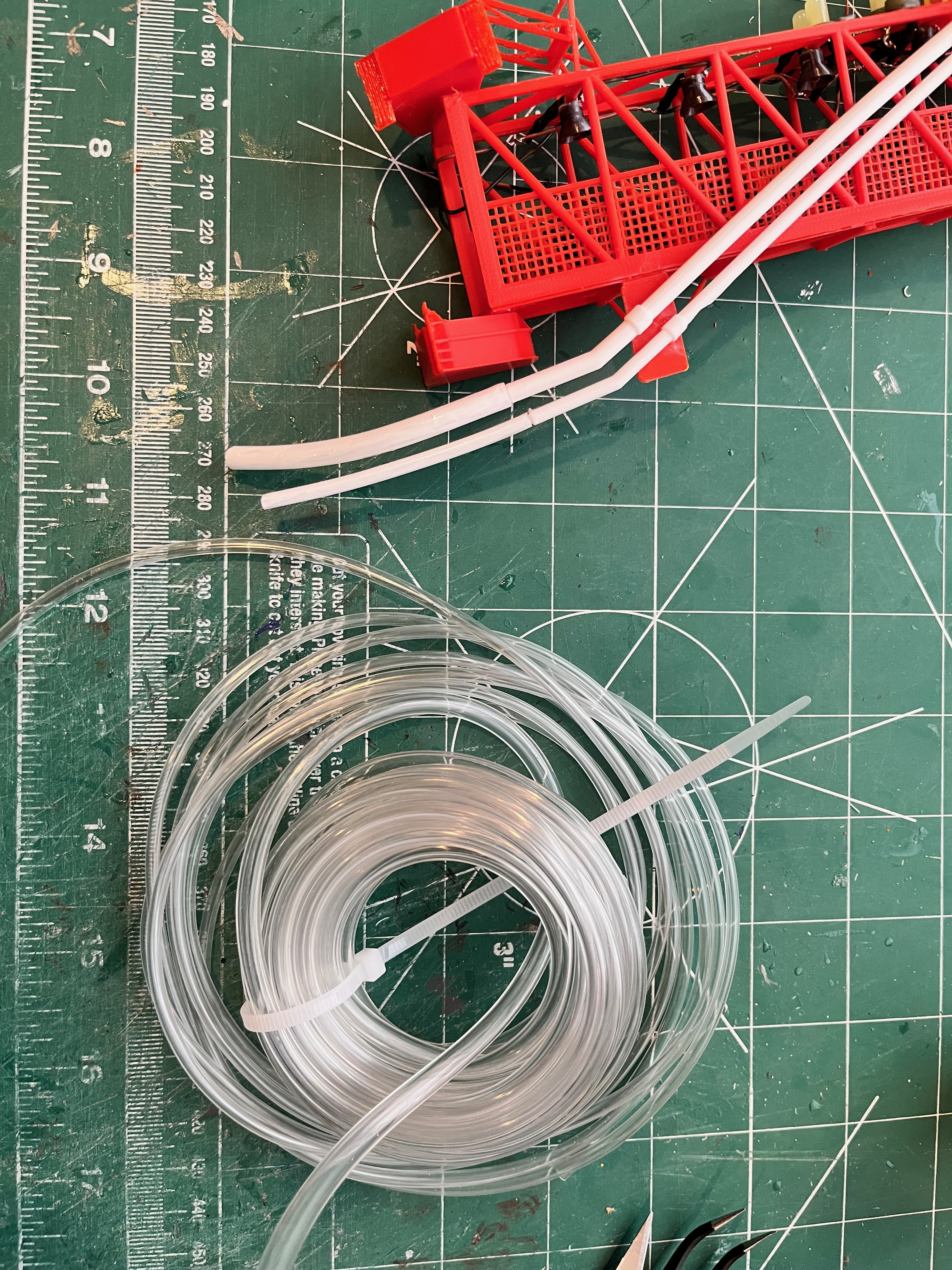
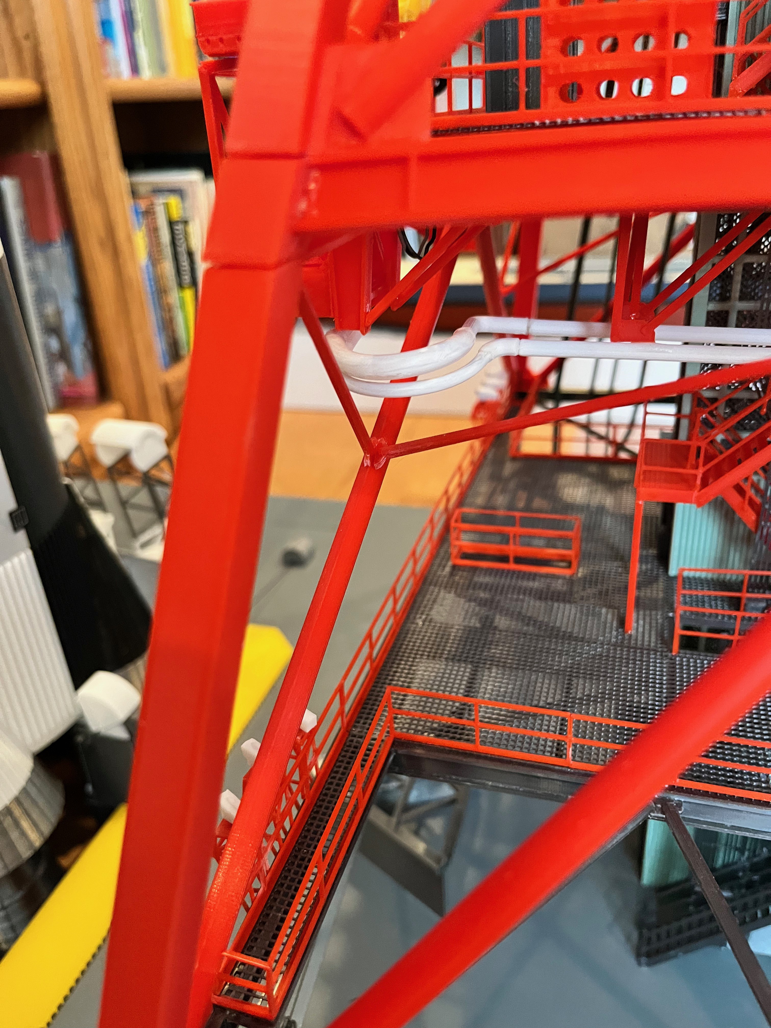
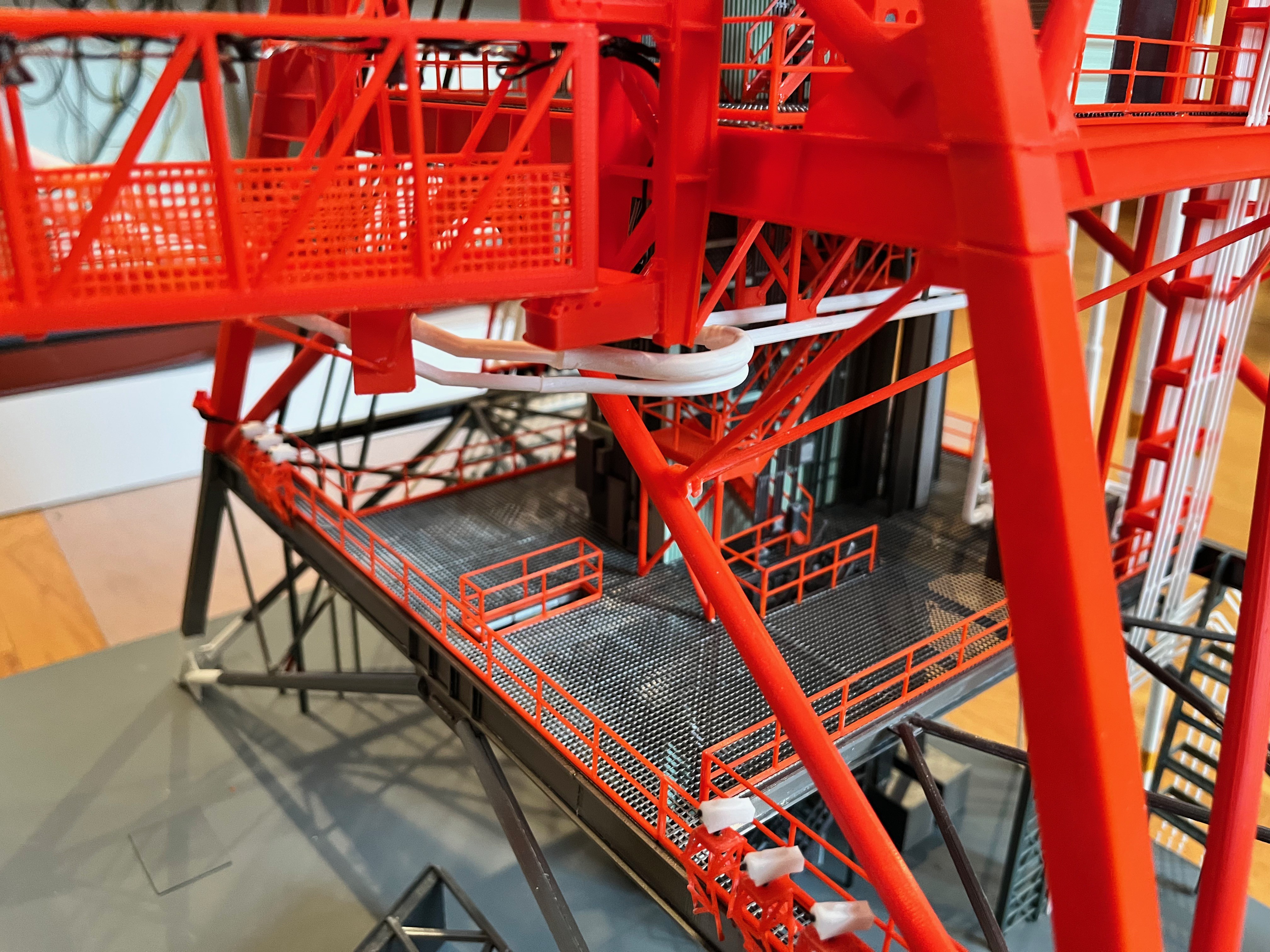
The tubing is a clear vinyl tubing, both 1/4" and 3/16" OD tubing. Fortunately this stuff is paintable.
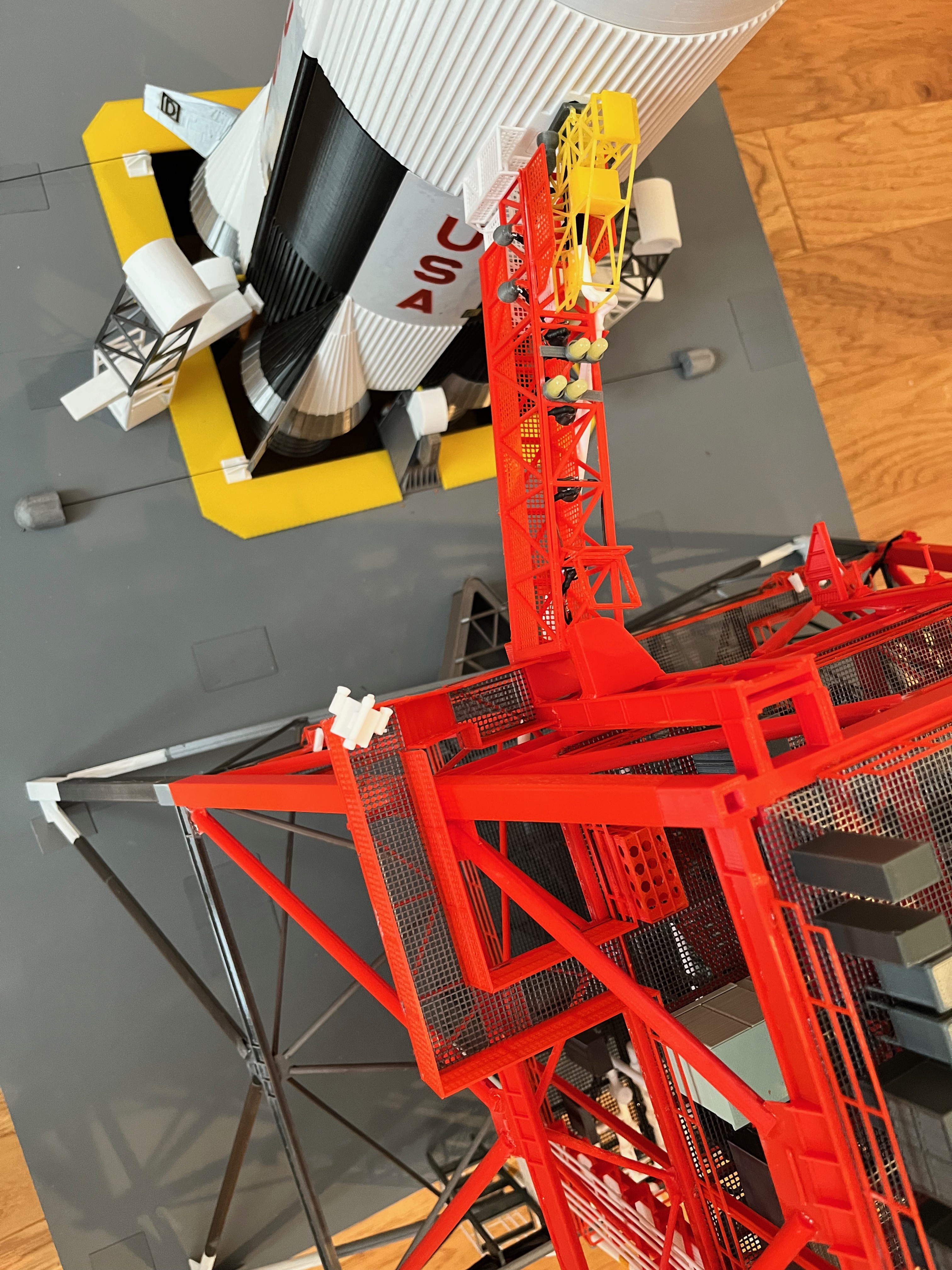
Swing Arm #1 Attached: The arm is attached! You can see a picture of it retracted and extended and lit. Four lights are in-board and two are out-board plus the two end spotlights.

The pipes that feed the LOX are not per the MicroArtwork. Those pipes didn't make sense when you look at the pipe bends both extended and retracted. The larger of the two vinyl tubes is much less pliable than the skinny one. Taking all that into account, this is my solution. You can see the tubes both extended and retracted.
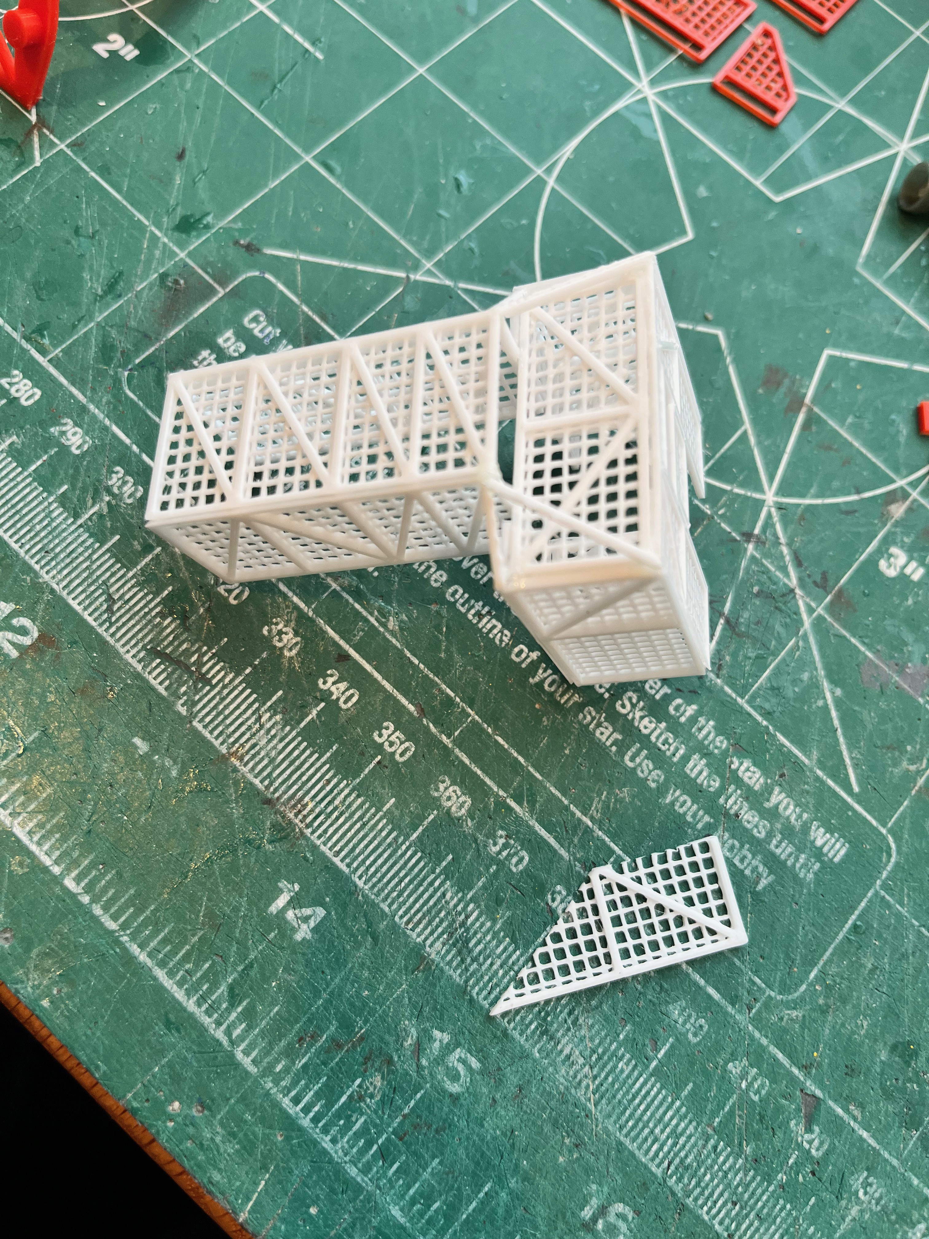
Swing Arm #1 Complete: The walkway is in and this portion of the model is now published. I was going to paint parts of the camera black but forgot to. Notice that the stair treads are not grating. These parts would have been too small so I made the treads solid (just a shorter version of the main stairs). Since swing arm #1 was 84 parts and rather complex, the other arms will also be their own models and therefore will be tackled as they come up.
Discussions
Become a Hackaday.io Member
Create an account to leave a comment. Already have an account? Log In.