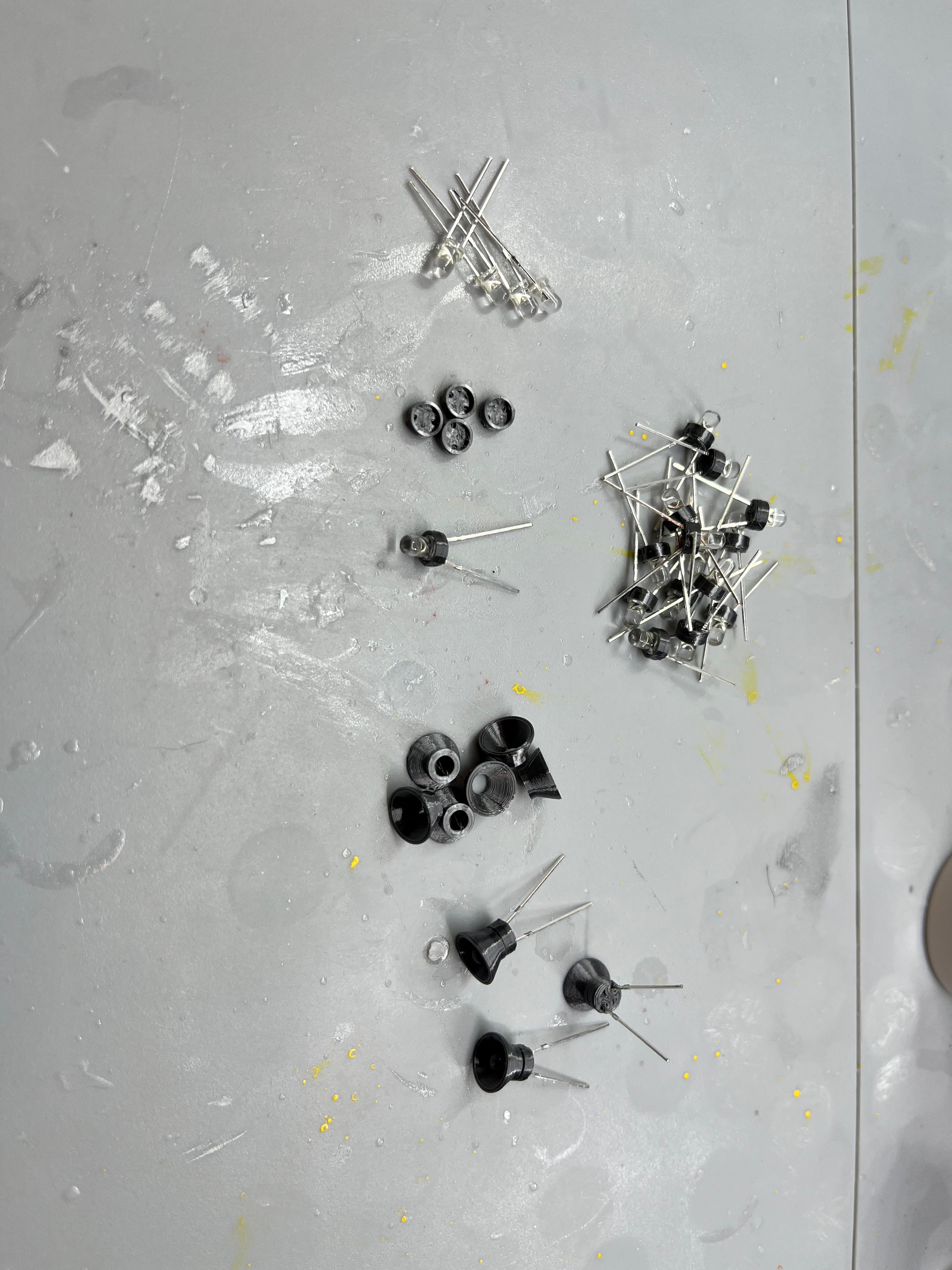
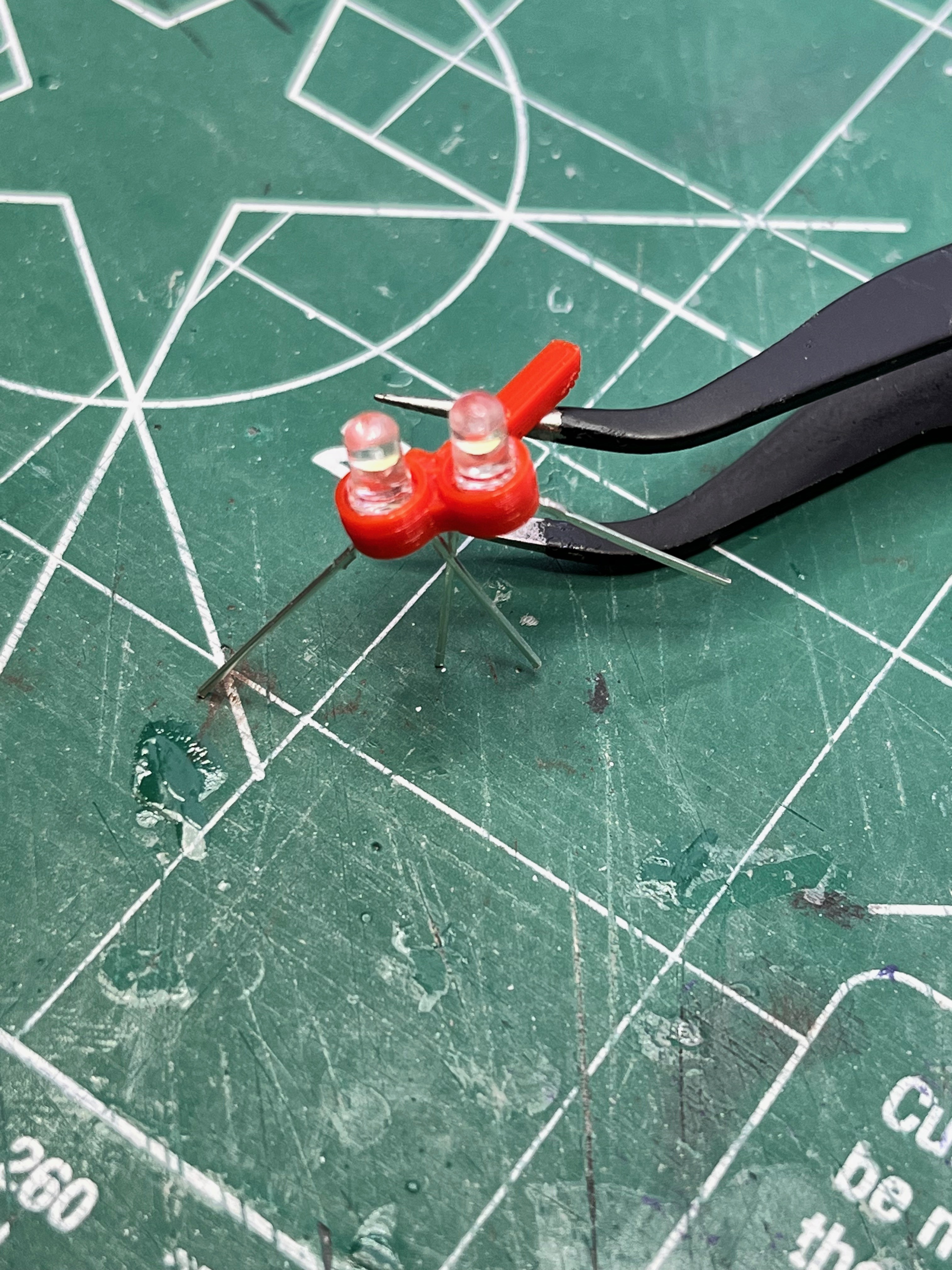
Lights: There are almost 250 lights on LUT, not including the swing arms. To get the correct scale look, the proper number of lights, fairly dim will be the best. For this I had a bag of 3mm white LEDs from a previous project. I ordered another 200, $7/100 from Amazon. To direct light downward and make them look good I created two pieces, the shade and a cap to cover the top.
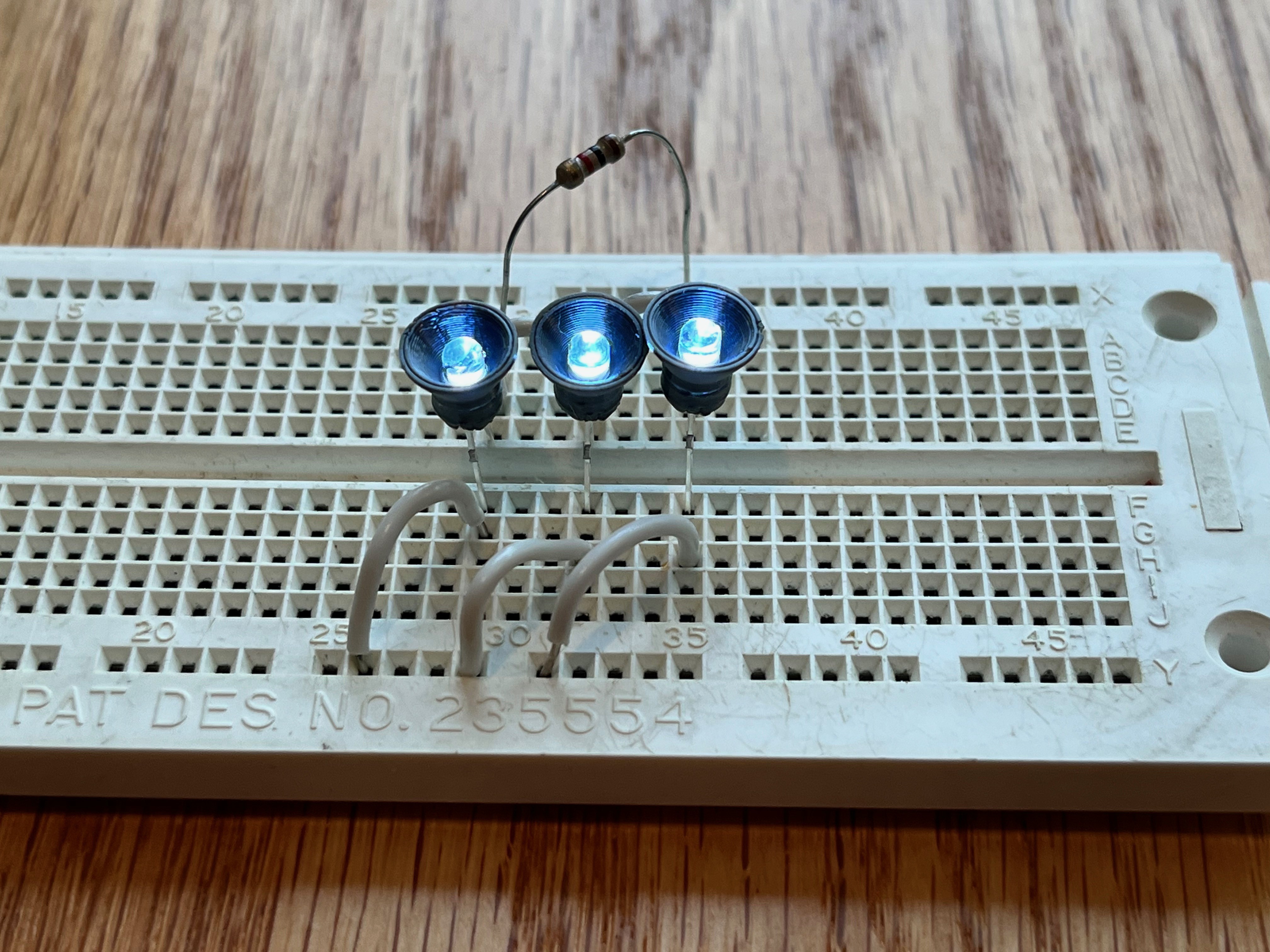
Here are three assembled lights being tested.
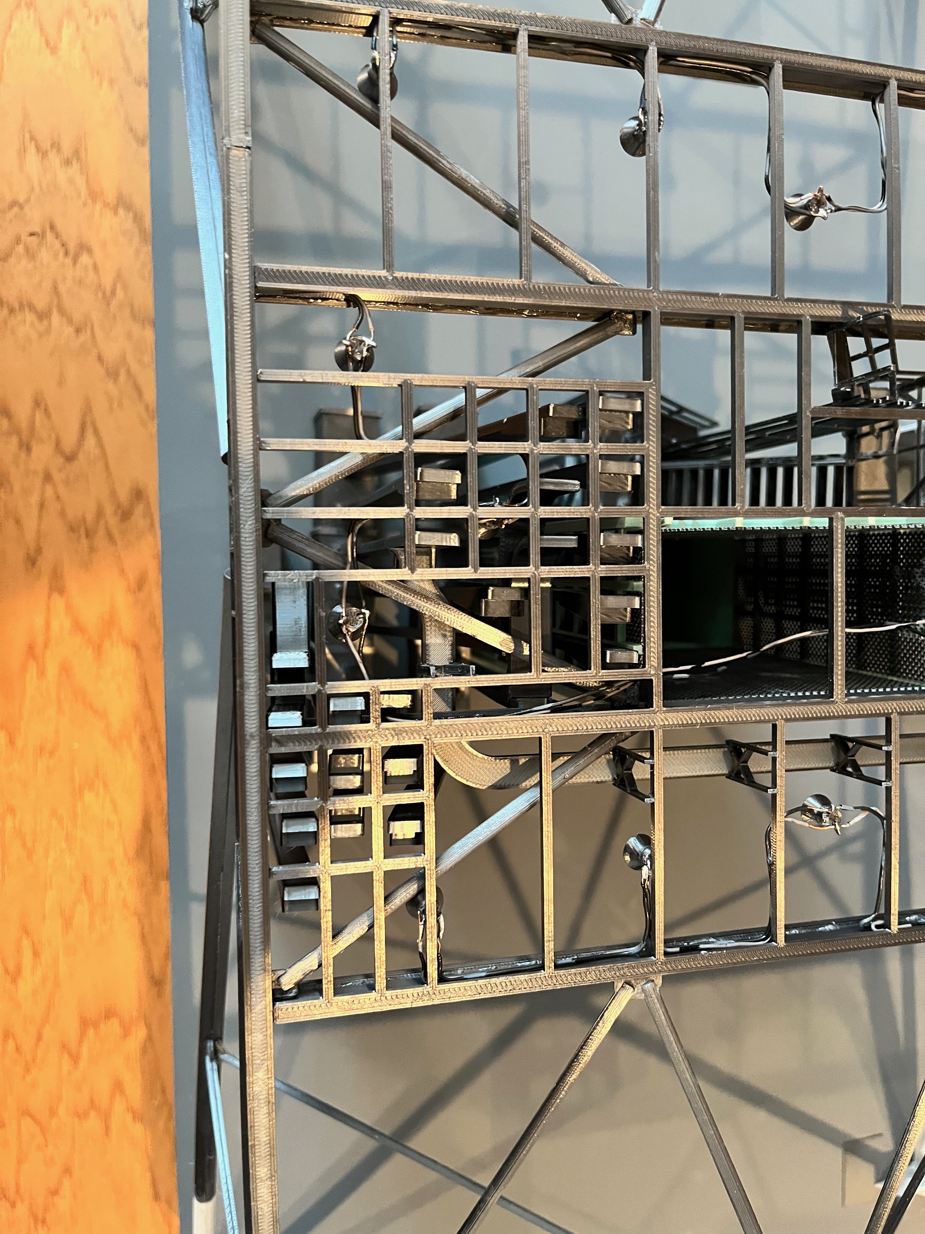
I wired up and glued in 5 lights on the underside of the level 30 floor.

I am always looking ahead 4 or 5 steps. Is there something I need to be considering now that makes things easier later on? So far I have done nothing with the swing arms. These are models unto themselves. Fortunately the main structural portions are common, the first and second elements. Despite this, some of the arms are very complex. I want this model to be as detailed as possible given the limits of scale, therefore the swing arms should articulate, both swing away and extend/contract. There should be working lights and accurate piping and cabling. The cabling should be easy, various size wires. The piping will be more difficult as there are flexible sections. The best material for this seems to be vinyl tubing. There are various small sizes available; 1/8", 3/16" and 1/4" OD. As long as these take paint everything should work. There is a good set of on-line pictures at turbosquid that show various angles and the ends extended and contracted. So far I have combed through these pictures and the various technical drawings out there to update the spreadsheet and sketched in an initial set of parts that may be required. Usually this first quick pass results in less parts than are required for the finished model. As a result of this effort, the total parts count is now up to 4,000. Bottom line? The arms attach to the support and locking columns that can be added on after the tower is built as will the external pipes that run up the tower. The one thing that is affected are the railings because there are walkways that extend out and around one of the legs to access the arms. I expect these railings to be added on after the tower is built due to their delicate nature.
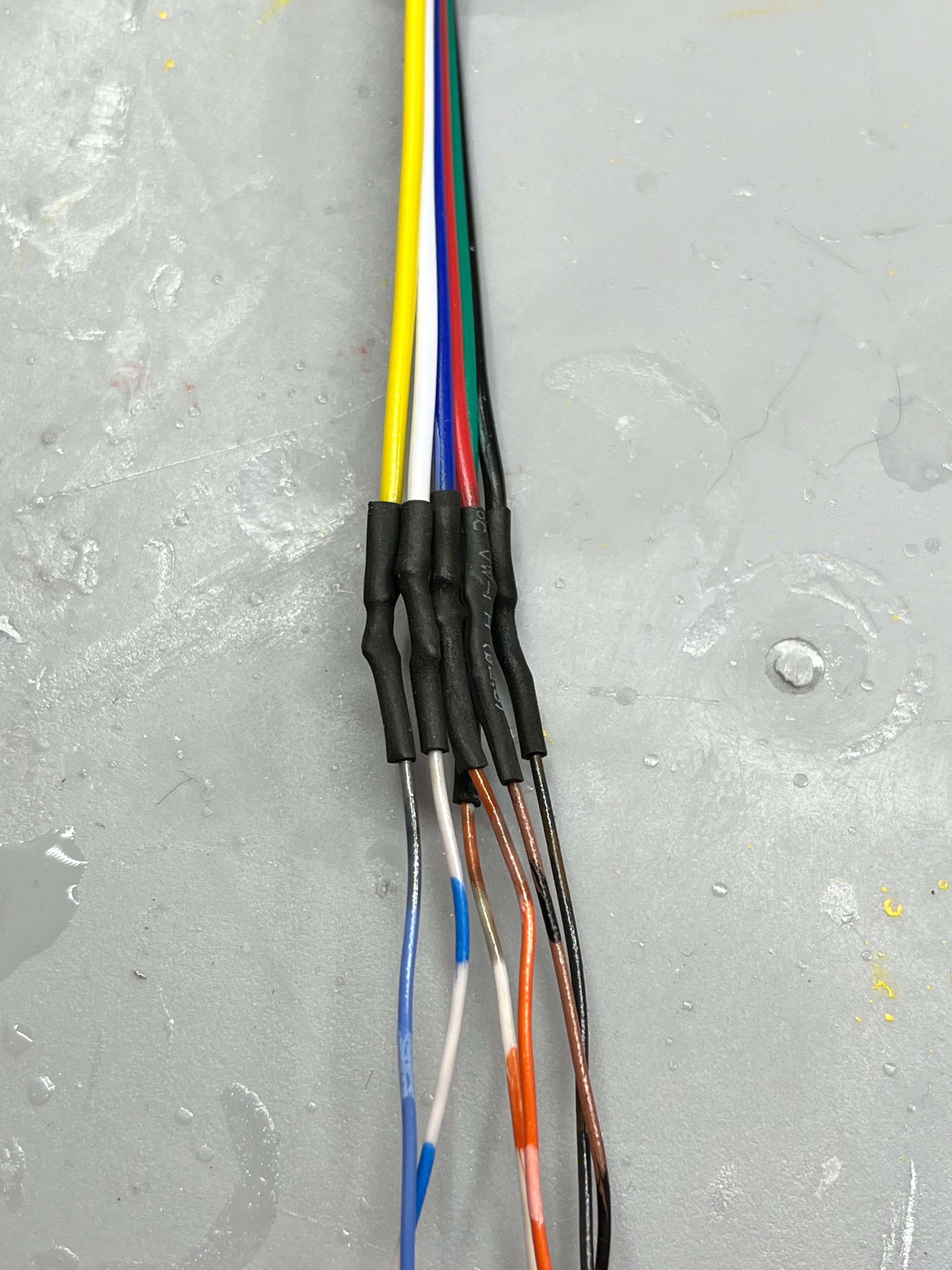
To glue or not to glue, that is the question. Actually the question is how much of the tower to glue together. The launcher base is large and heavy. I should definitely be a separate piece. As far as the tower goes, having each floor separate seems to be too much. At this point I think if I glue together levels 30/60/80 that would be a good chunk of the tower that can be easily managed and manipulated. The Support and Locking columns split at that point. From there I plan to glue the tower in 3 section chunks. That would be 100/120/140, 160/180/200, 220/240/260, 280/300/320 and 340/360/380 with the crane probably being separate. This means I need to have connectors at every break for the six wires running up through the elevator shaft. I plan to have the swing arms removable as well. The lower hinge can be glued to the support columns with the upper hinge being split into two pieces that dovetail together with the base glued to the columns. The swing arms will need a two wire connection for their lights.
I have completed a restructuring/renaming effort to make more sense of the parts. The farscape1 model lists parts with a prefix of say "L60". Are these parts above or below level 60? Same thing with the Aviator67 parts. It appears the Aviator67 parts designation mean the parts sit on or above level 60. For the farscape1 parts it appears the parts are on or below level 60. This has been confusing as I am printing and assembling parts.
What I have done is denote levels as say "Level 60-80" which means the parts that sit between level 60 and level 80. I have not renamed the existing parts so the "Level 80" structure parts sit between level 60 and level 80 (the level 80 floor beams and legs that support level 80). It also contains the Aviator67 parts that sit on top of level 60.
I hope this makes sense.
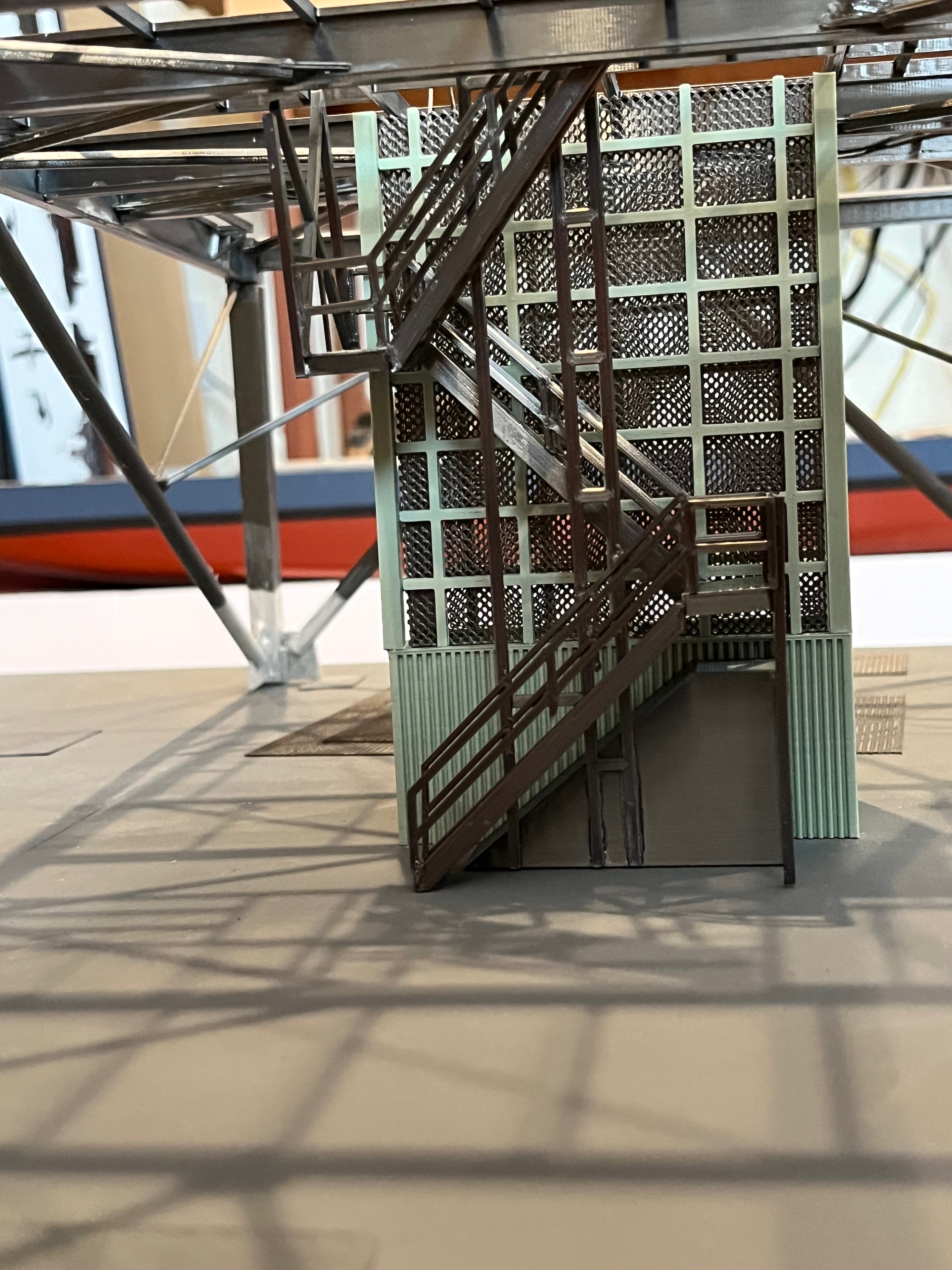
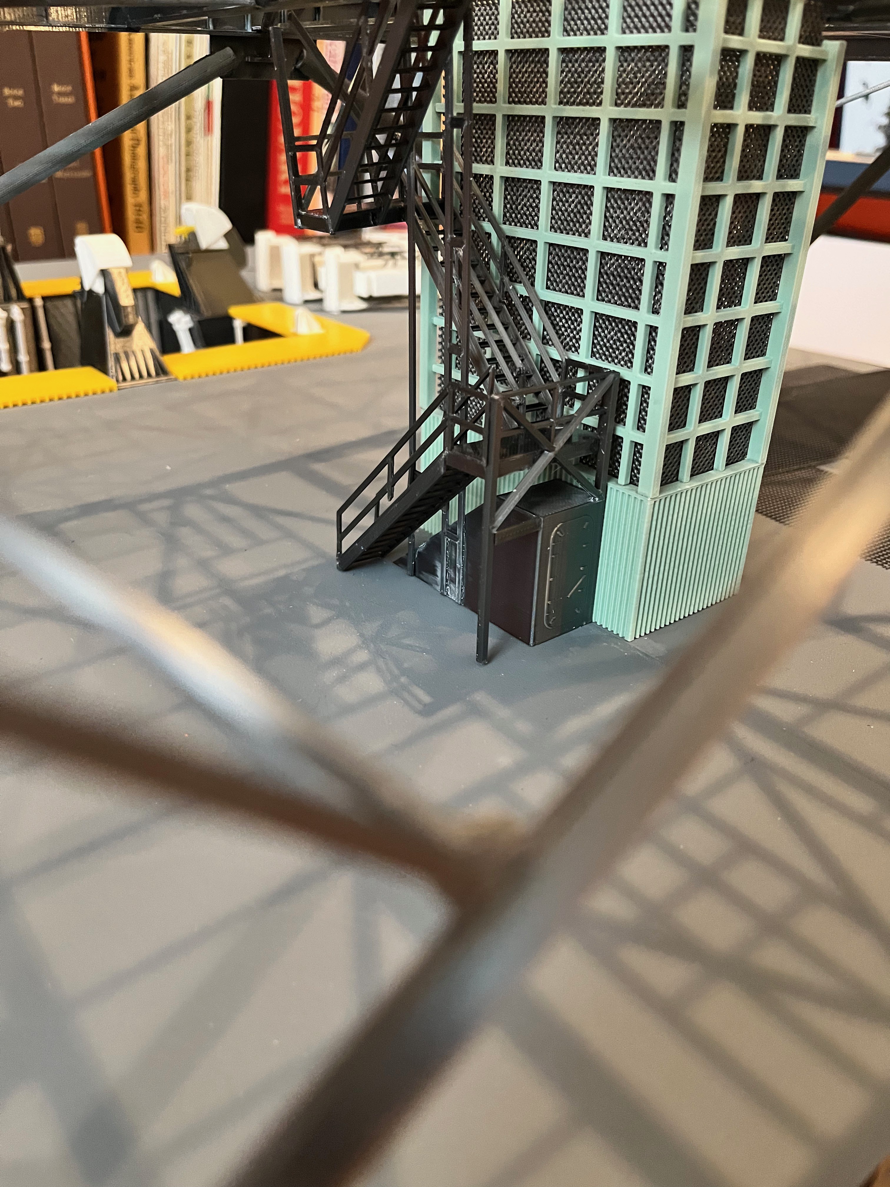
I have built and dry fitted the elevator shaft and stairs up to level 80. This includes piping that runs up through the stairs as well as the elevator pipes that Aviator67 produced. I have now decided to publish these files that go all the way up, however I have not verified anything above level 80, but much of it is repeated. Near the top I will have to add some more files related to the stairs.
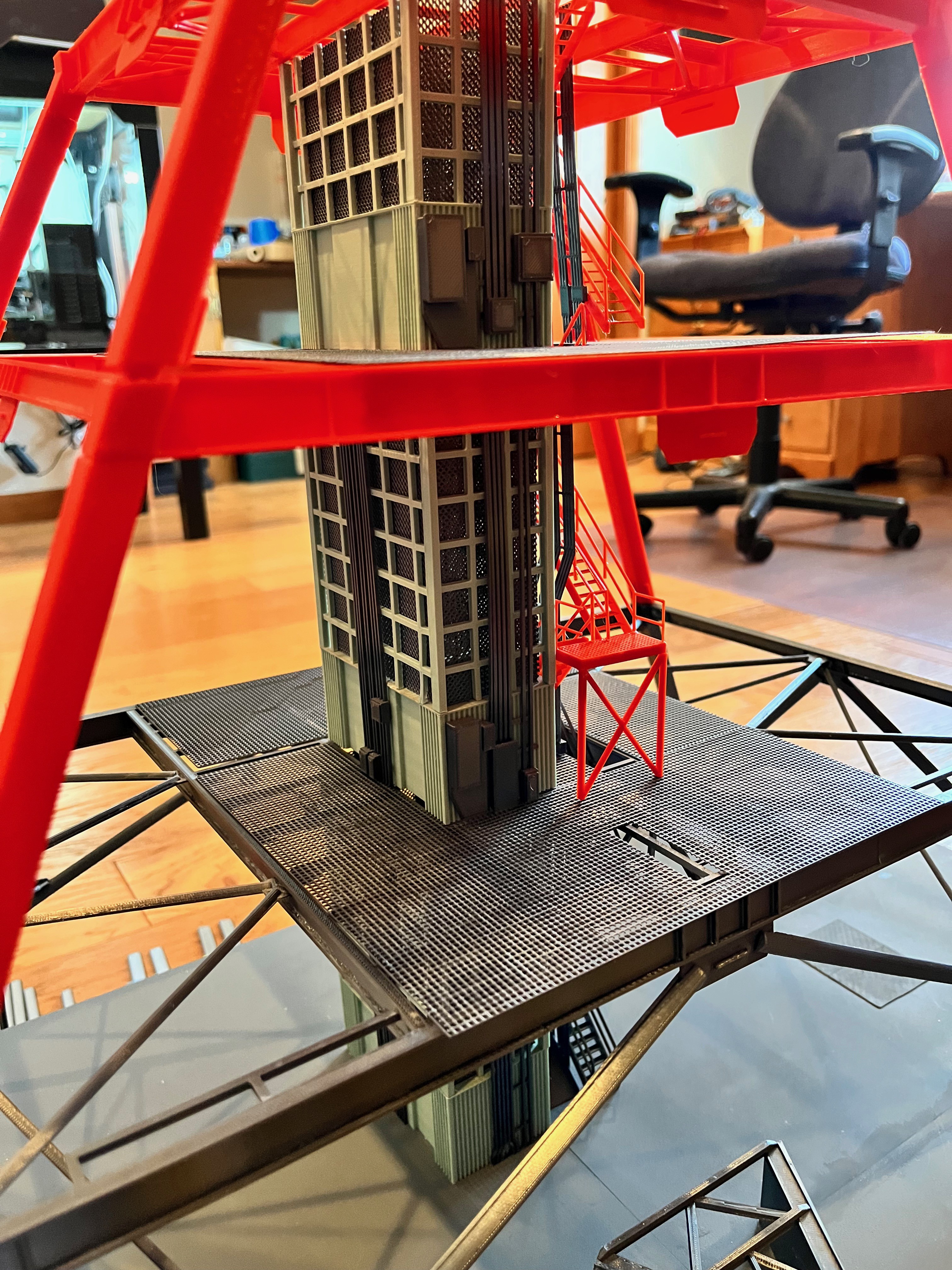

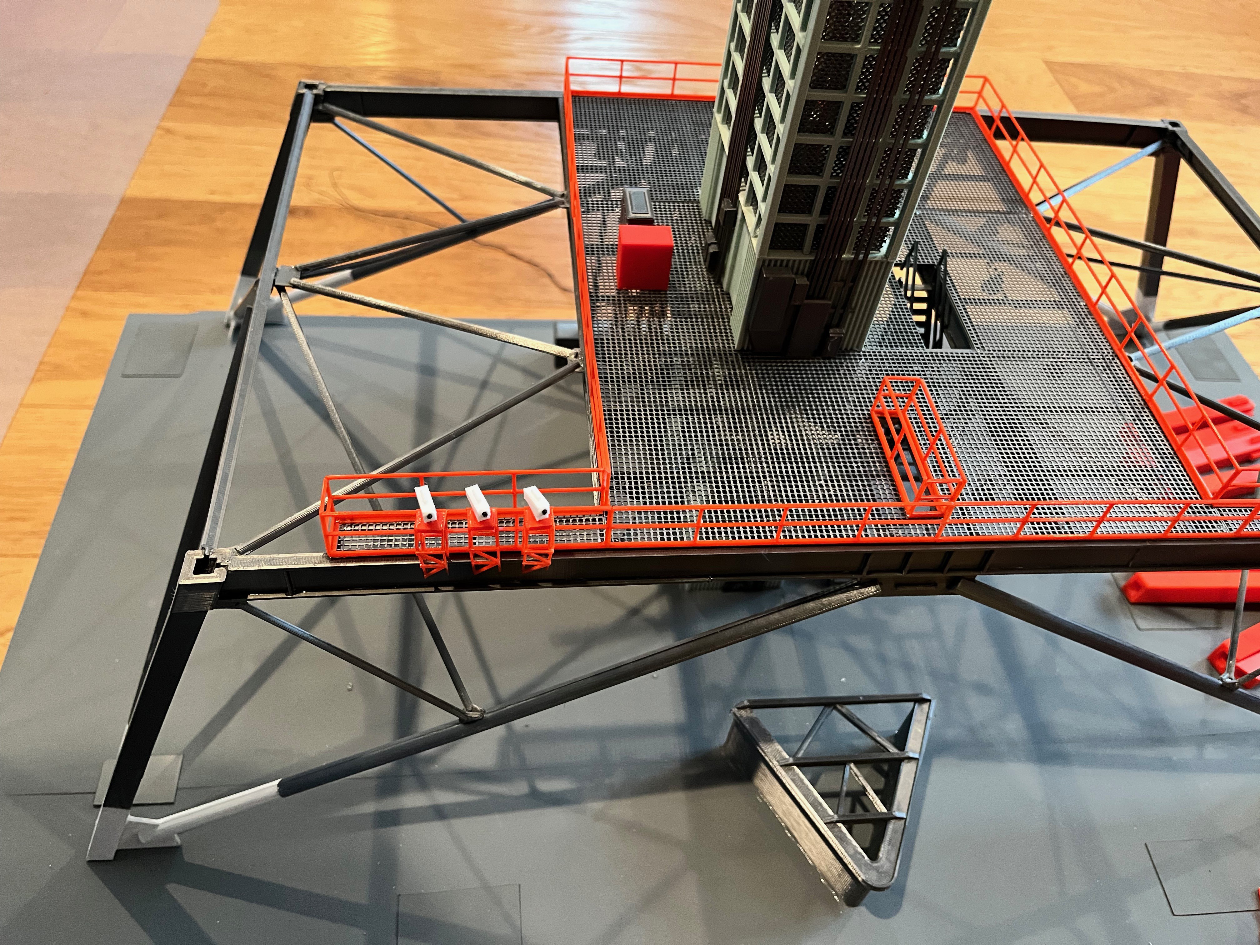
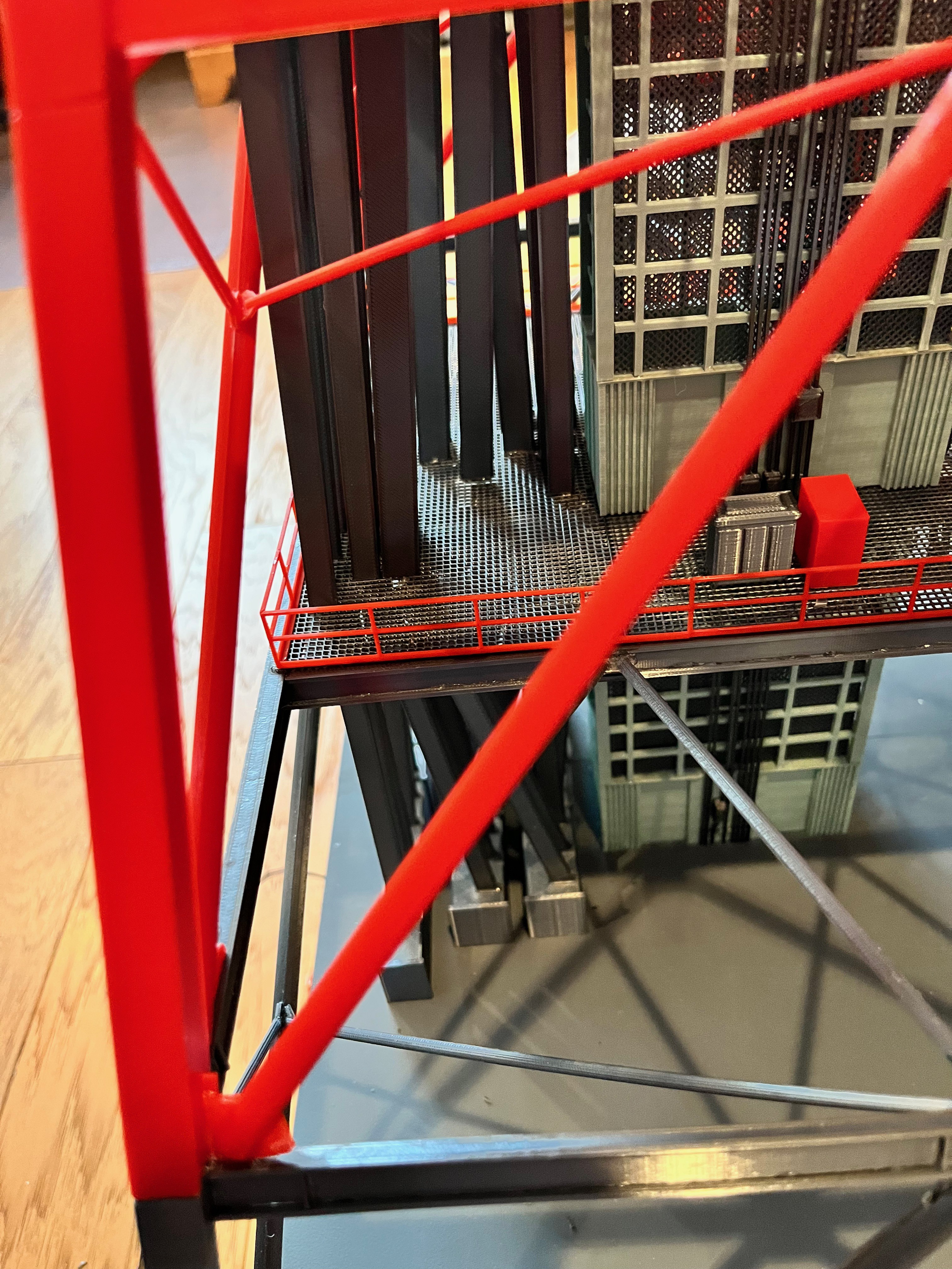
And here is the level 0-30 cable trays. I am happy the way this difficult section turned out. You can see the horizontal cable tray hanging from the ceiling. The little tray hangers worked well. After gluing them on I used a sprue cutter to nip off the ends flush with level 30 floor.


You can see where the first connector is at level 30 with enough slack built in.

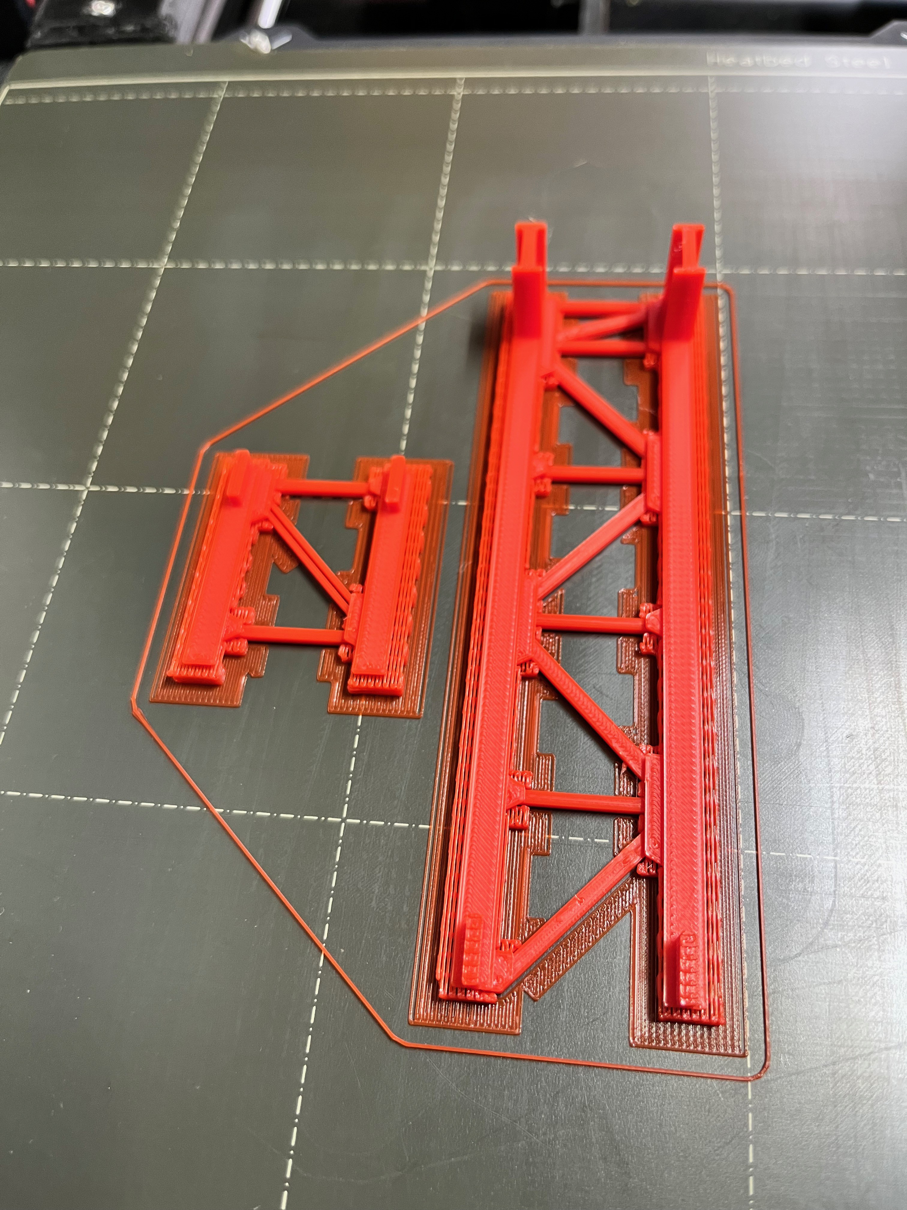
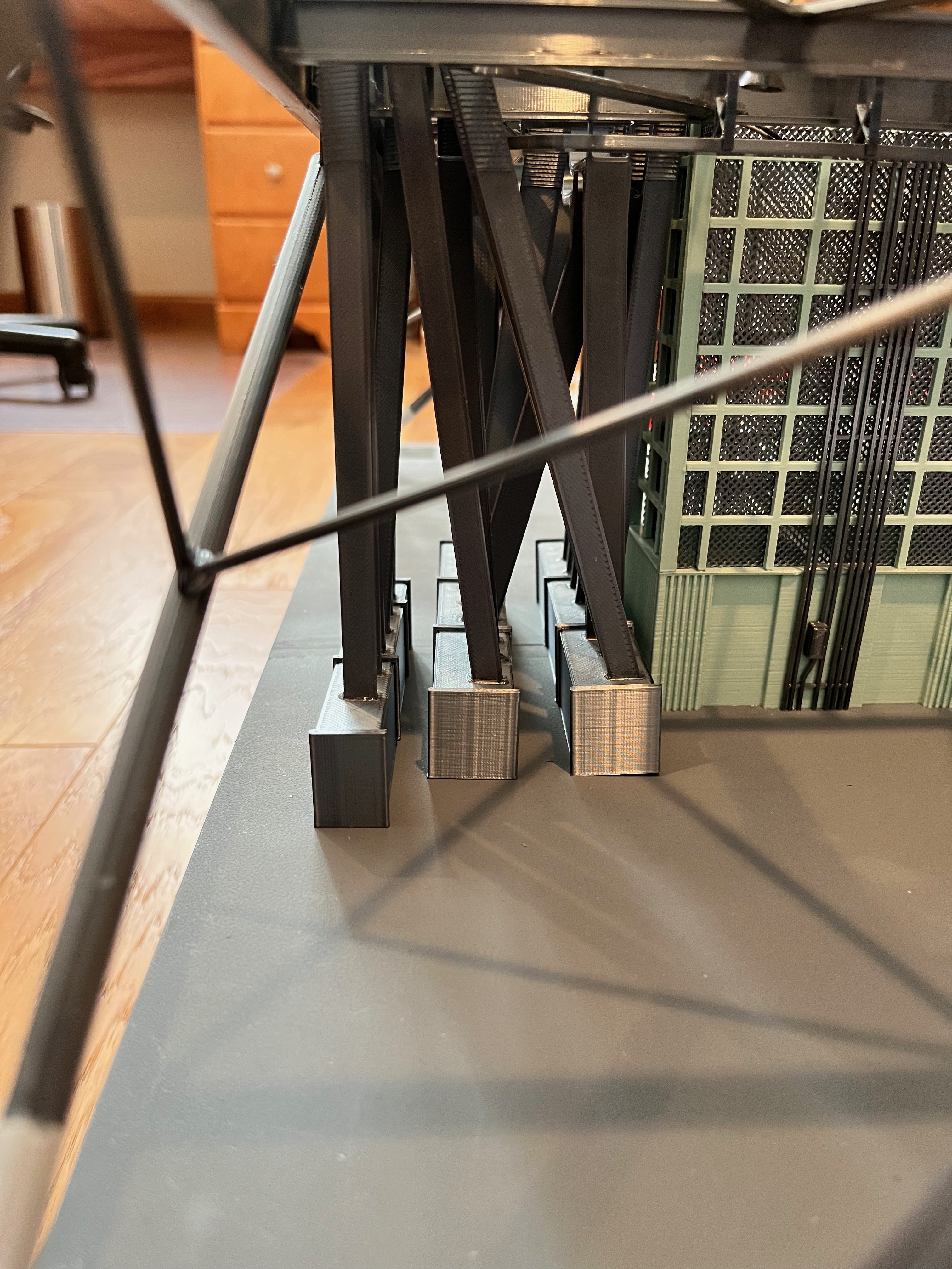
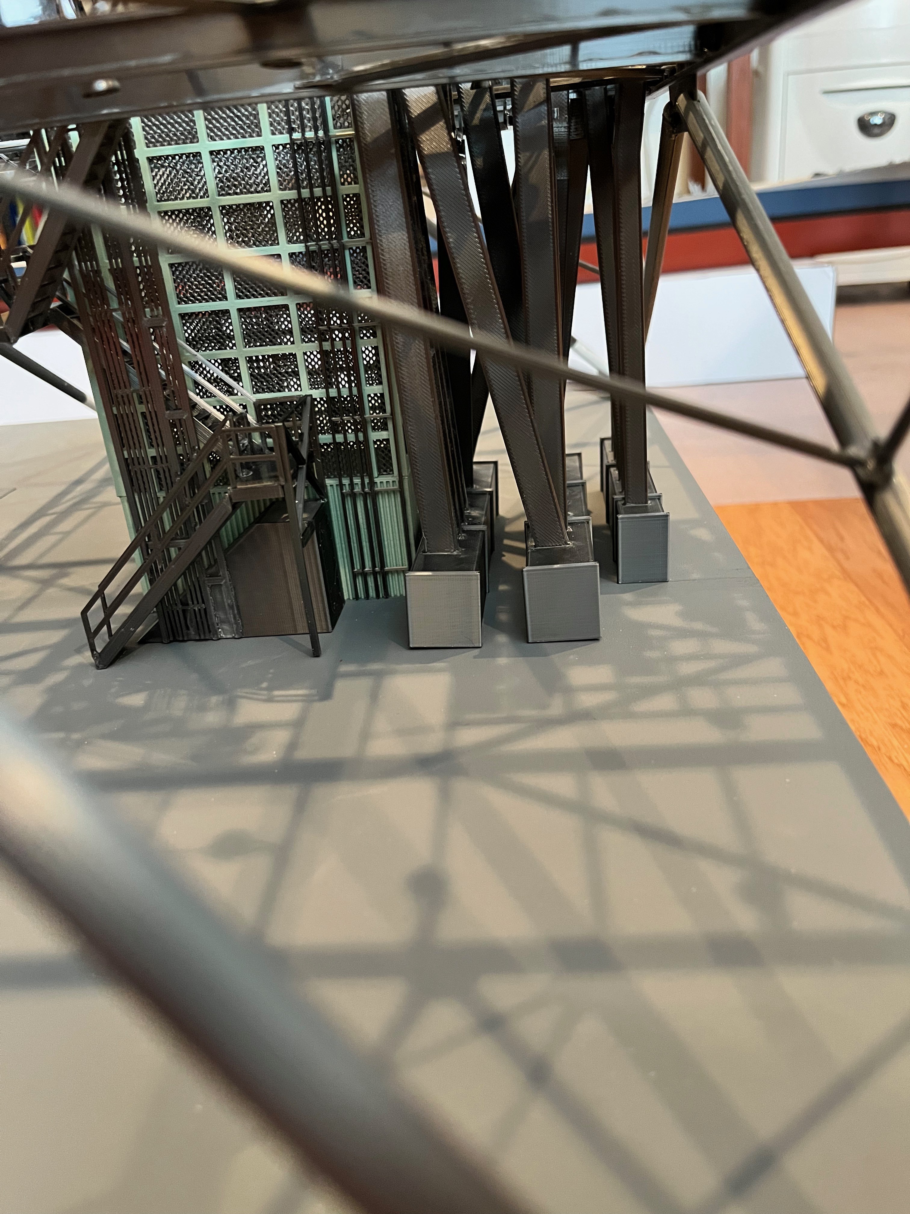
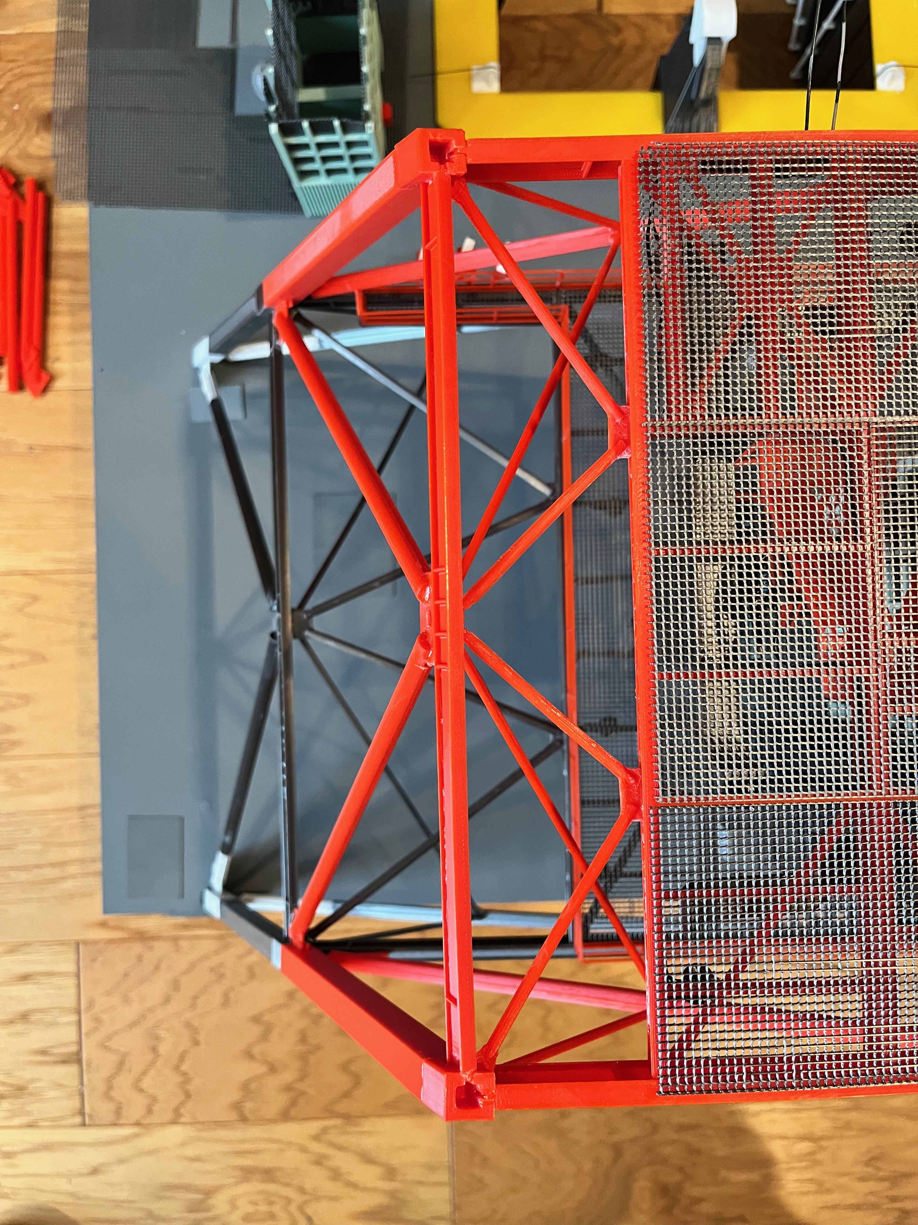
Here are the parts for the lower support column with the print supports removed.

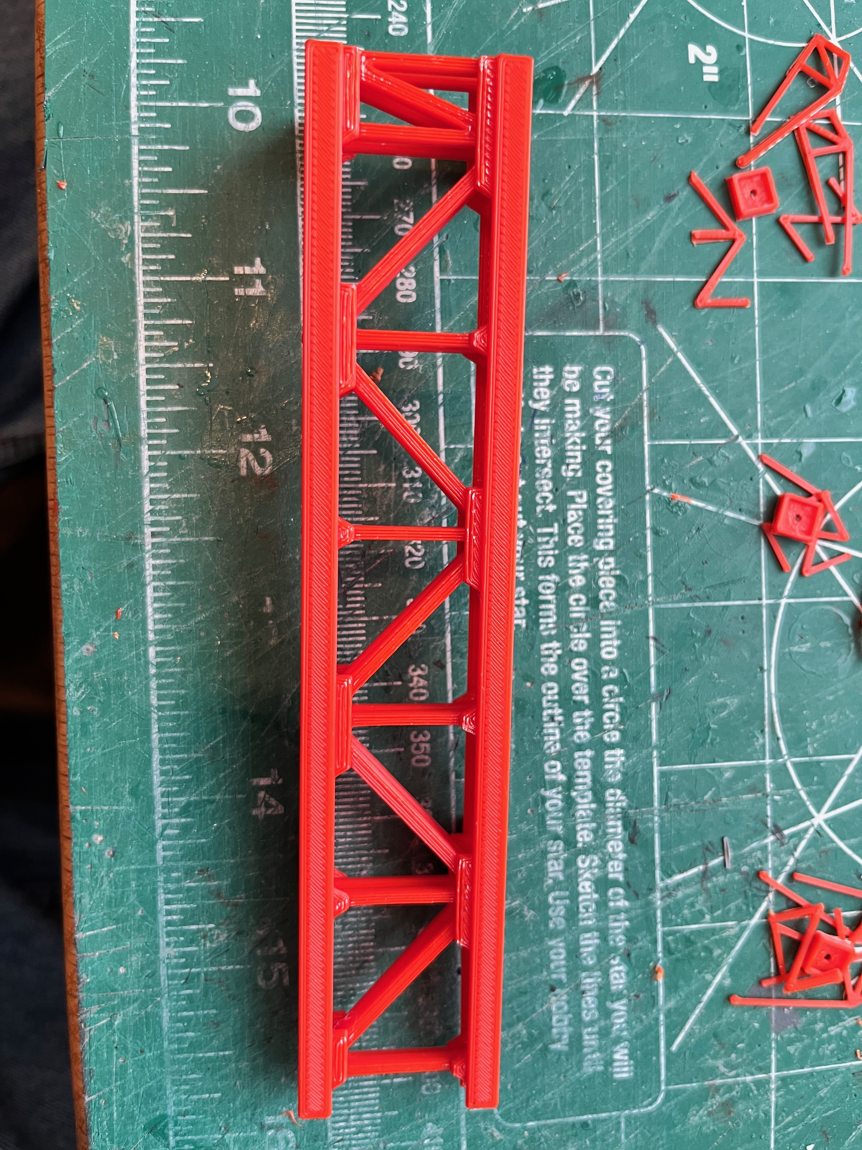
There are still lower cross braces to hold the lower part that extends below level 60 that I still need to design. The only pieces that are not exactly correct per the drawings is the width of the vertical I-beam's webbing which I made thicker for strength and the L-brackets which I made square, again for strength.
How to slice up the tower? I definitely want working arms that are removable. Not yet sure if that's possible. I am fully committed to the model having removable sections, although you can certainly glue it all together. Beyond that I was initially thinking 3 levels at a time. Now that I am designing the support column I realize that if I section the support column into 3 level sections it will require parts that are over 304mm long. While I can print those on my larger printer, I have been unhappy with that printer and have been using the Prusa printer for everything. It has a print plate of 210 x 210 with a diagonal of 297. There is no way to print sections that long on the Prusa. What if I go with two sections at a time? I am a visual person so I drew up a diagram to understand how the arms come into play. Some of the arms are packed so close together, some of the support columns need to be split mid level so both hinges are attached to one printed section. It turns out the best way to split the support column is 2.5 levels per section and the removable sections just so happen to alternate between two and three floors at a time. This is my plan and I'm sticking to it. At least until I find a flaw with it, then it will be time to pivot...


Here is level 80 with the light strand laid in and then glued in. I realized that it is easier to add the lights before installing the small under floor braces. A lesson learned for the remaining floors. Notice that for these early floors i was using shrink wrap and then decided later on to omit the shrink wrap. I also realized that the lights are attached to the underside cross braces.
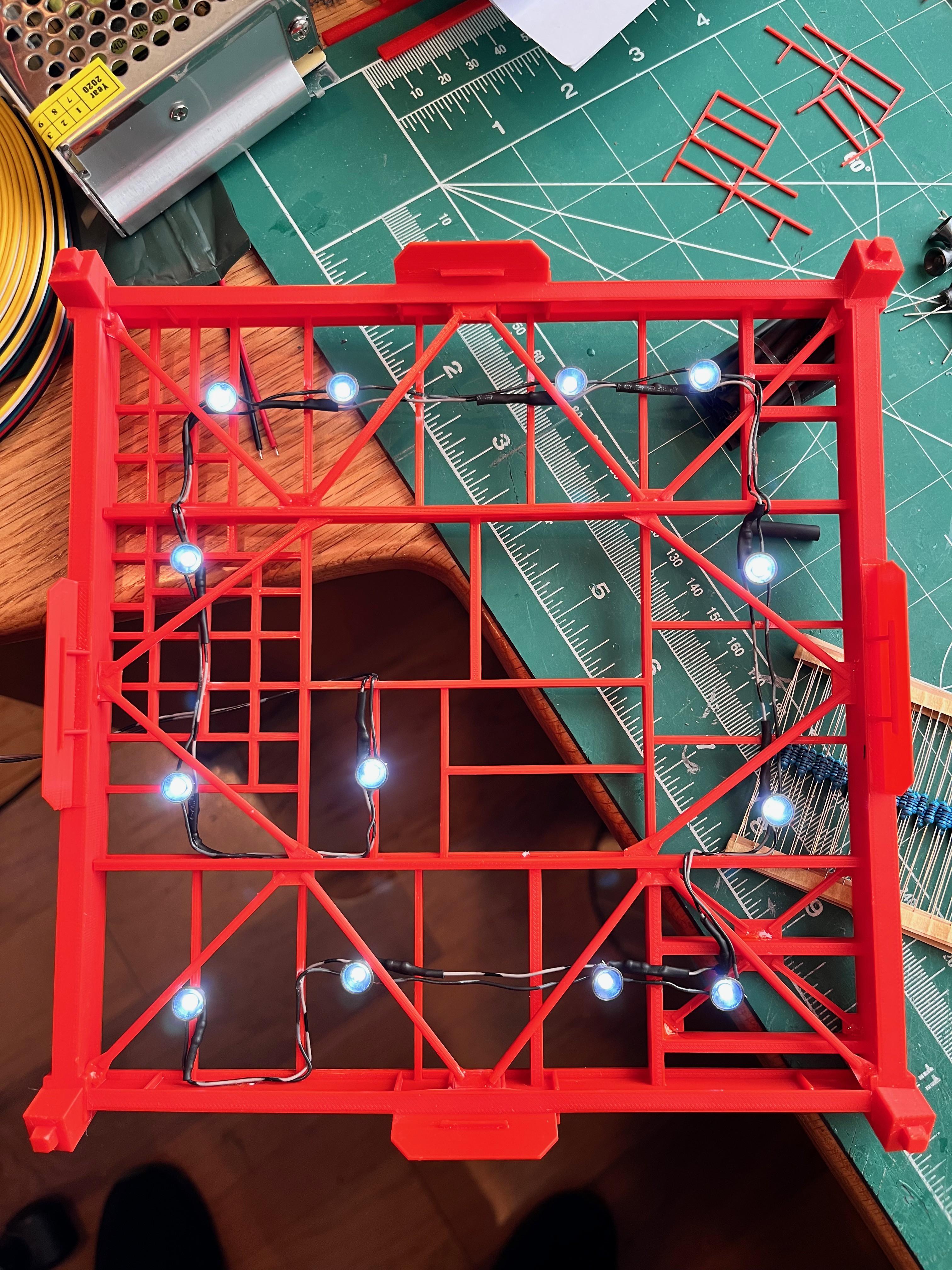
And once the sun went down I took pictures of the first floor section with the lights off and on. The 1k ohm resistors seem to be just about right.

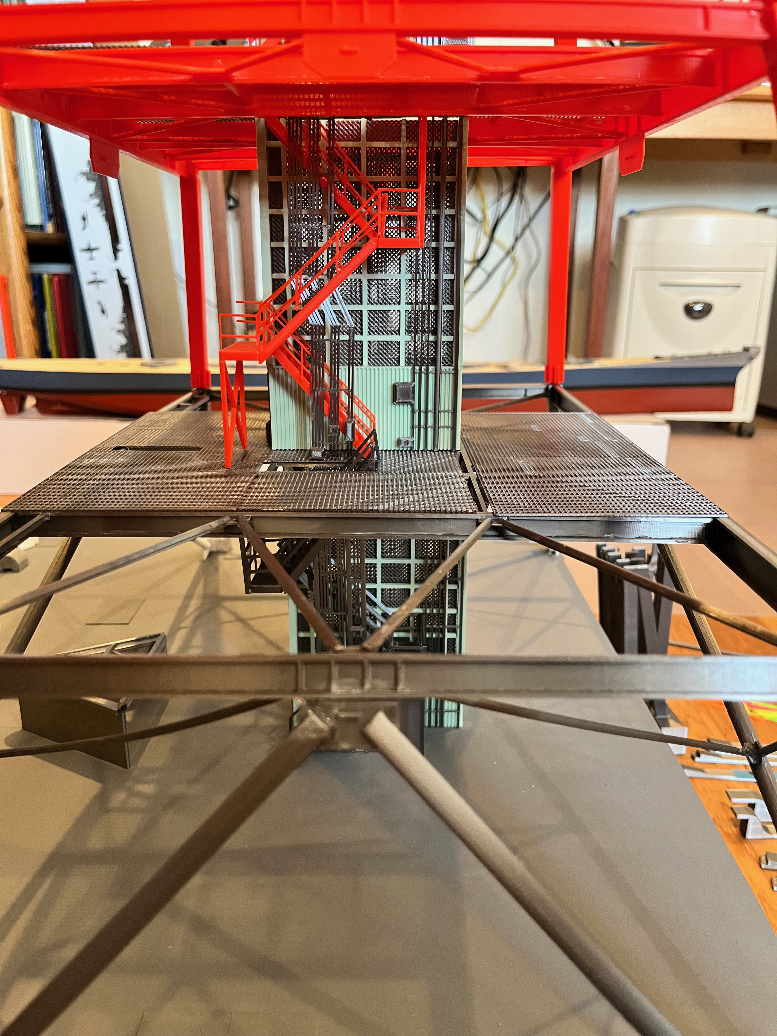
The level 60 floor is now glued to level 30. I added the 6" bracing that holds the long 16" floor brace in place. Like level 30, I waited until the floor and bracing were on since the inner braces are at compound angles. It was easier to simply measure and then make the parts. Those are now out on Printables. The next level of cable trays are also glued on. Once I finish up to level 80 I will publish the cable trays. There are a lot of unique parts and I have been correcting some errors. In the first picture you can just see two wires sticking out where Swing Arm #1.
I am complete with the internal bling on Level 60. The LOX valves (thanks to Aviator67) are in. The mounting legs had to be trimmed a little to get the pipes to fit between the hand rails. There are new parts to get the two pipes across the space over towards Swing Arm 1.


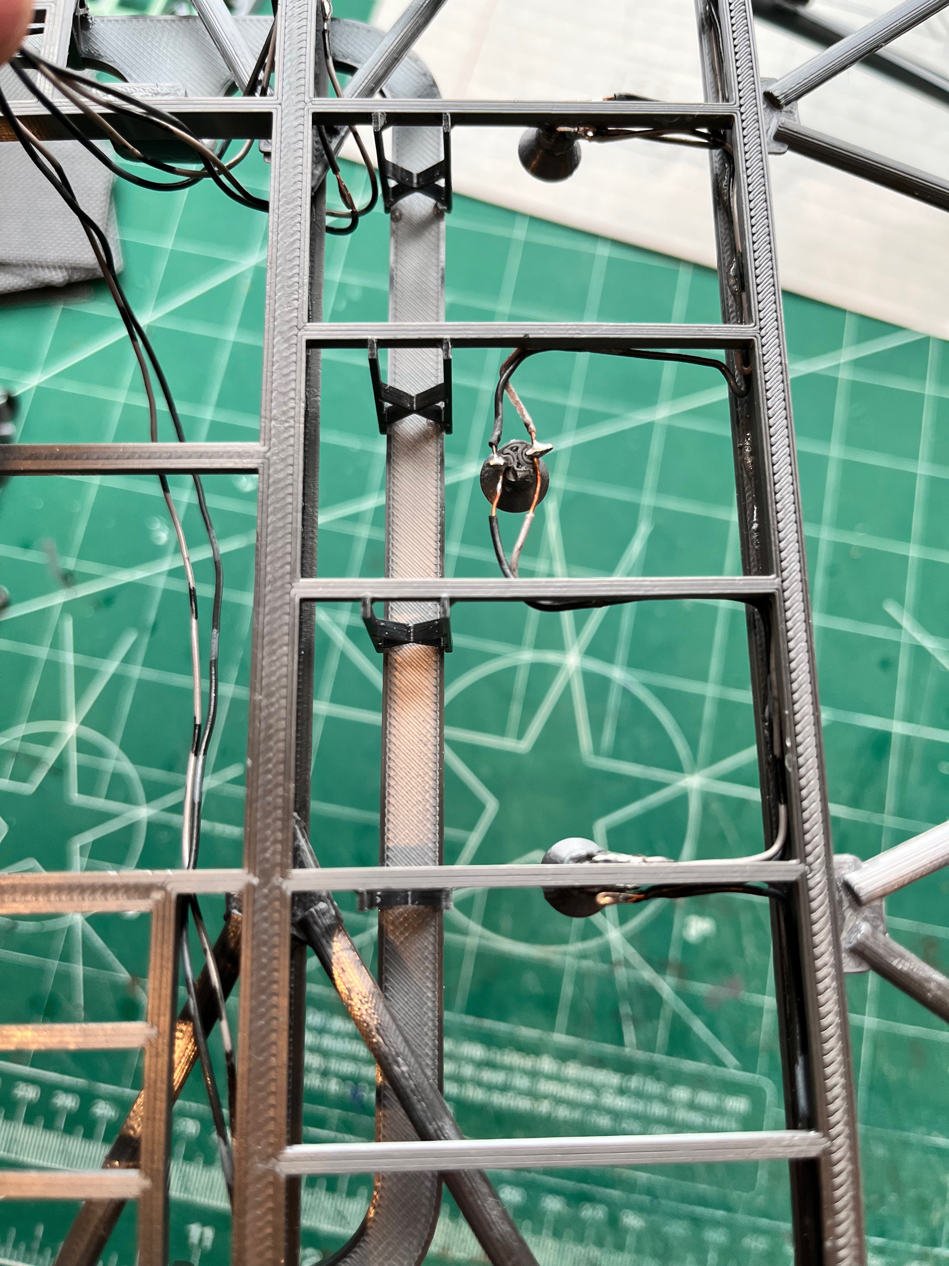
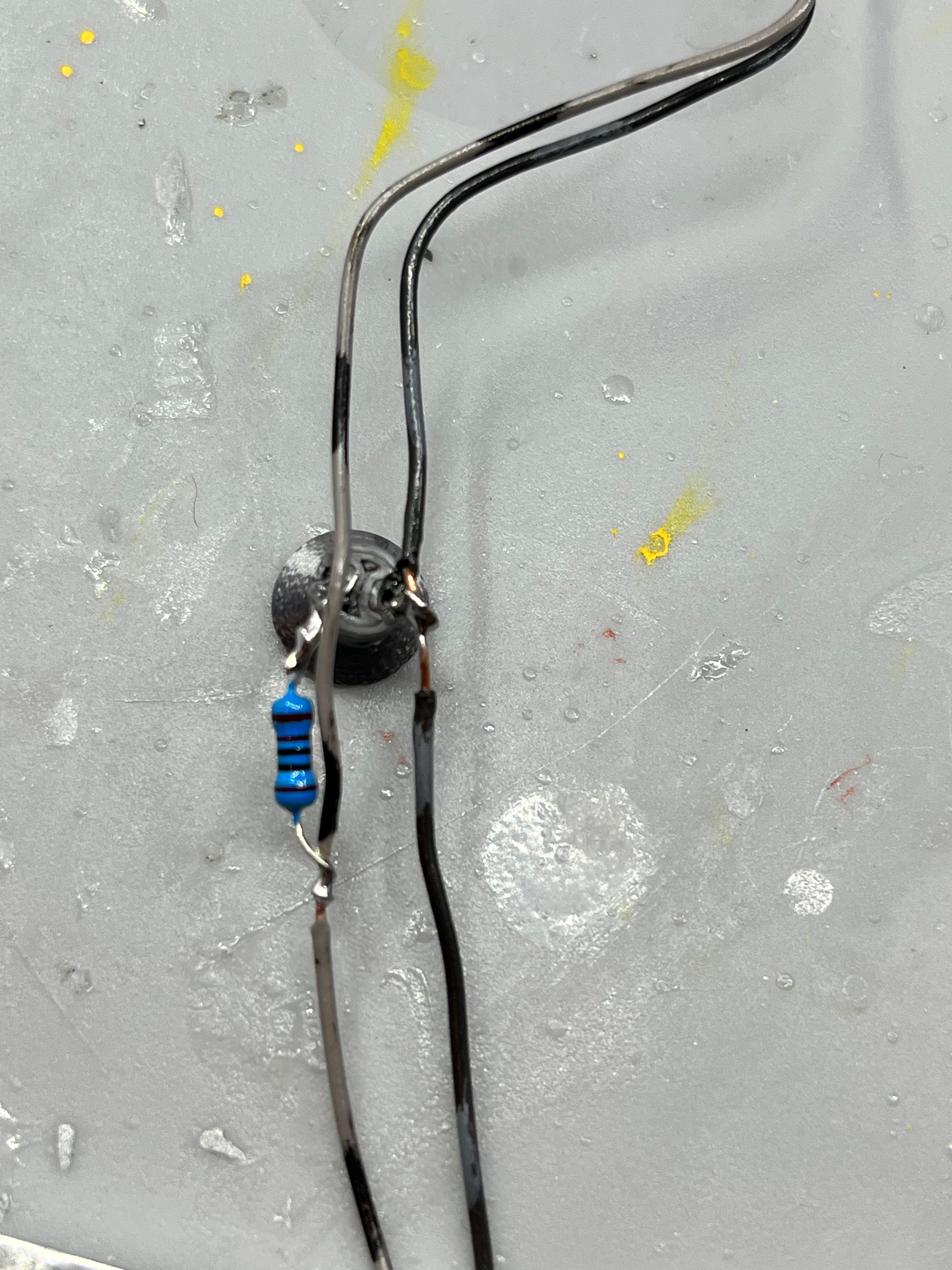
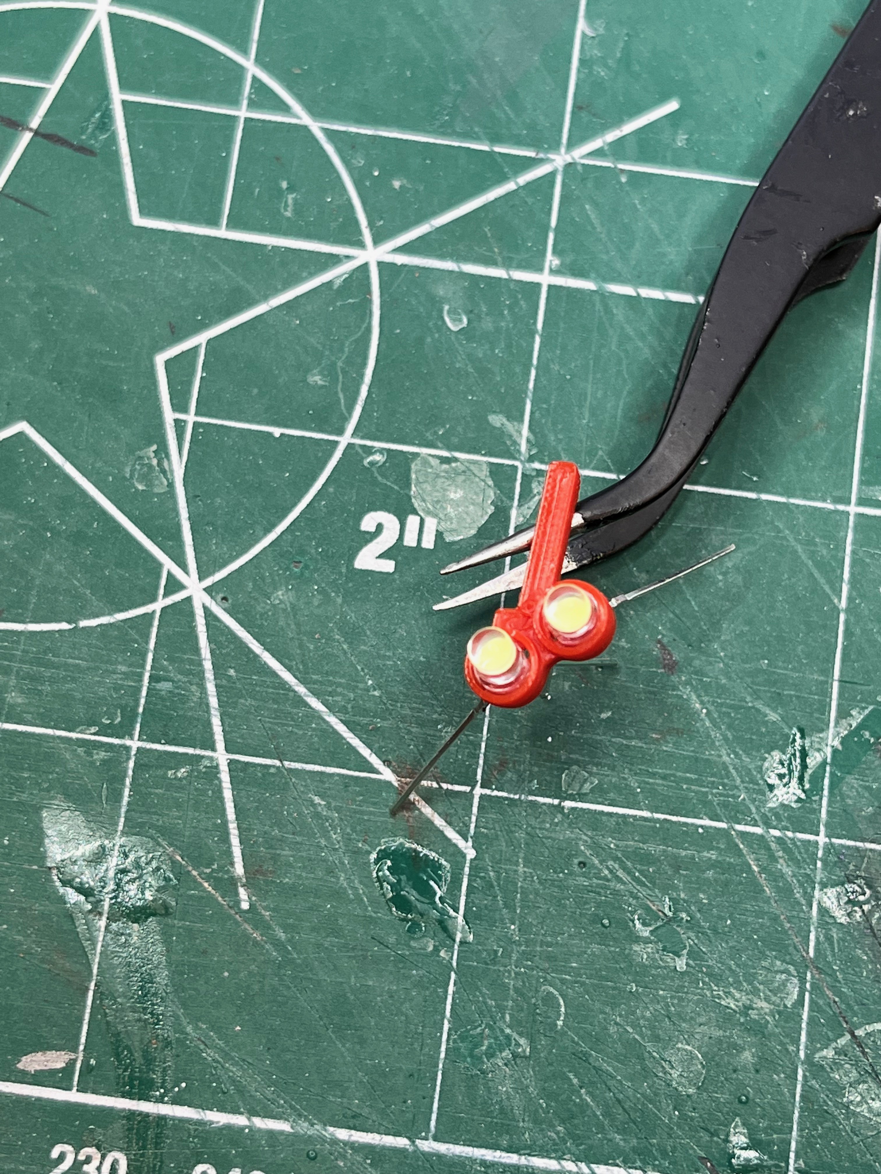
Here is a test print of a holder for the pair of flashing lights based on the previous light cap. I don't have any red 3mm LEDs so I am testing with white. The idea would be to solder the inner two negative leads together and then solder three wires that would go around the leg, under the little arm that somewhat shields the wires and provides a better glue surface. The resistors would be located somewhere else, below the floor grate or in the elevator shaft. I will need to use a really fine soldering tip.
For the pipes going up the side I am going to break with convention. For some reason most modelers shy away from supports like it's some kind of curse. After making the two sections of 18" LH2 pipe that go up the first section of the tower I split them and sliced them and then sliced the whole parts. The whole parts with supports take 18% less filament and 13% less time to print. Why? Because the split pieces have solid outside layers that go through the middle of the part. The whole parts only contain infill. In my opinion the whole parts look better because there in no seam down the middle or any chance for mis-alignment and there is less assembly time. I'm going with whole pipe parts. If you ascribe to the no support ideals, then by all means, feel free to slice the parts in half.
Side 3 LOX/LH2 Expansion Joints Decoded: I could not make sense of the Aviator67 parts. I took a look at 75M-05753_35 and 75M-05868_09 in the Cato Library. You can see in the attached spreadsheet (out on Printables as a CSV file when I publish the Pipes) that I listed each joint type by level, the number of required joints by level, the actual pipe size and the model pipe size. I then listed all the Aviator67 parts that I could find along with the opening size for the pipe. The pipe designators did not match up to the documents I am looking at, however the MicroArtwork and TurboSquid almost match up. There is one missing joint in TurboSquid. I really like the look of the Aviator67 parts and really don't want to re-create these. Some are close enough to work as-is while others are close enough that I can simply scale them. To avoid confusion I am going to rename all the parts to match the documentation. The documentation also has lengths of pipe between levels and/or joints. I will split the pipes between joints and between tower sections so as to minimize the number of parts and have the parts fit a 210x210 printer. The parts will then be listed by level or if they span levels, listed with the first level they span.

The warning lights at level 30 are on. I used a pair of red LEDs with 470 ohm resistors. Fortunately I decided to build the tower as removable sections so I was able to remove the first section, turn it over and route the new wires.

You can see in the above picture a hint of the LH2 and LOX pipes on Side 3. And below is a picture of Side 3 with the LH2 pipes and hydraulic pipes complete. Unfortunately the expansion joints from Aviator67 for some reason were made with two different hole diameters. These hole diameters need to be the same. I took the largest EJ file, combined the two halves, sleeved the larger hole to match the smaller hole and then spit it in half. The other smaller EJs were then scaled to size. The LOX pipes still need to be added to the Launcher. Then it's on to Side 2.
I have started working on the pipes for Side 2. Aviator67 has very nice expansion joints for the ECS pipes. Unfortunately there is an error in those expansion joints. Fortunately the fix is easy. There are 10 pipes at the lower levels labeled E1/E2/E3/E11/E9/E10/E4/E5/E6/E7 going left to right. There are three sizes I will call small, medium and large. The pipe sizes, left to right are S/M/L/M/M/M/M/L/M/M. The Aviator67 expansion joints have E4 as a small pipe. The Micro-Artwork and TurboSquid both agree with the original documents that this pipe should be medium. I simply edited the expansion joint STL file, removing the small part and copying in a medium part. Problem solved. The pipes will all be modified to have connection joints and to be solid. I will also make the lowest section of these pipes printable as grey per the pictures. There will also be non-glued connections where the tower sections meet.
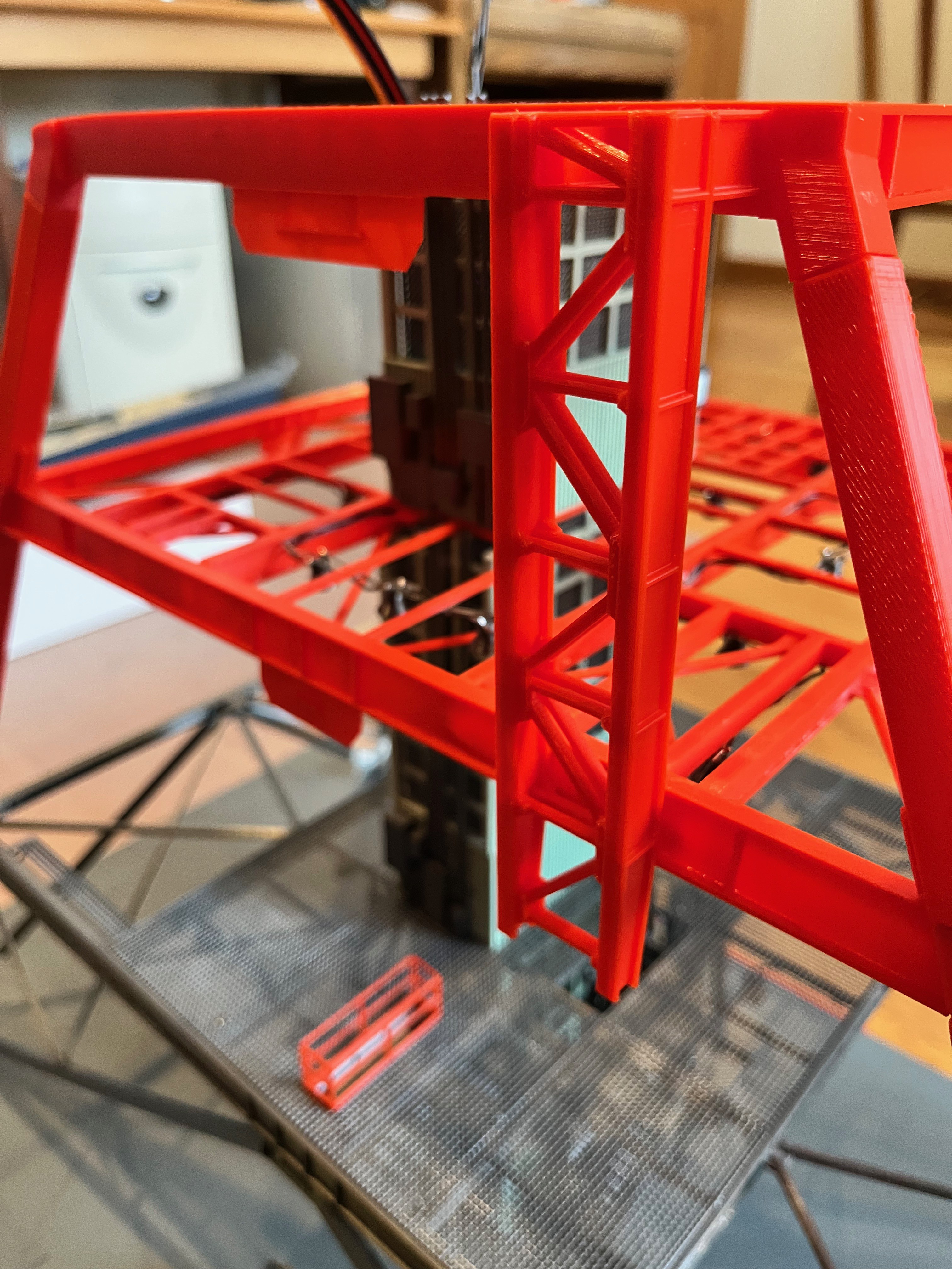
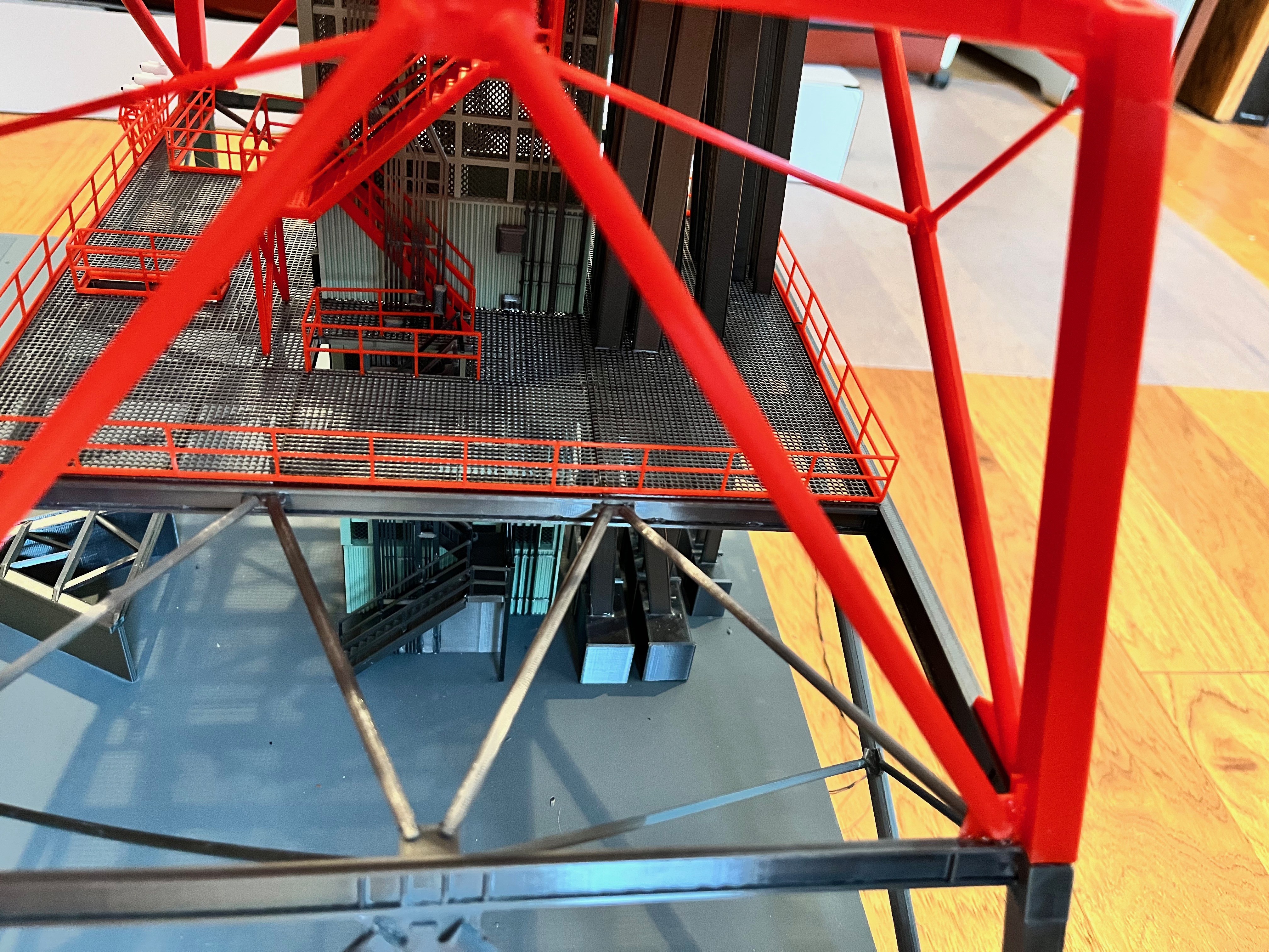
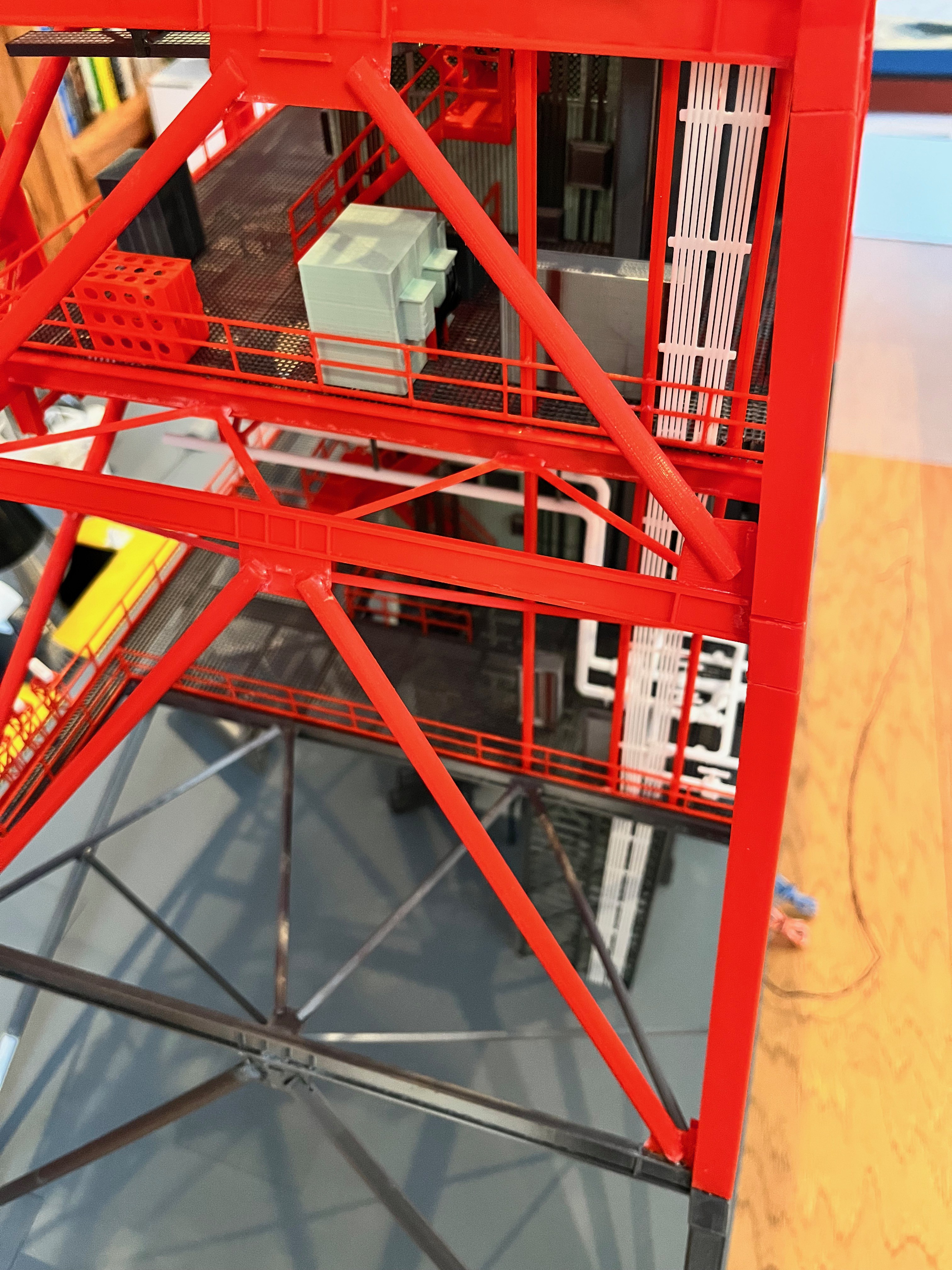
Part of splitting the tower into sections is deciding what to include in the lower section and what to include in the upper section. Here I chose to glue to the level 80 floor the equipment, railings and elevator shaft. The rest will hang from floor 100 to include the stairs and cable trays. For some reason the added equipment parts was missing two of the boxes to the left. I simply created boxes of the correct size and glued them on. The other thing you will notice is that I have use the sprue cutters to nip off the top of the elevator. Because the floor beams get smaller as you go up the tower, the elevator shafts should be unique per level. I decided to make one elevator shaft from level 80 up. For these lower levels the I-beams are larger so the elevator shaft needs to be shorted a few millimeters. The good thing is that the tops of the elevators are not really visible.

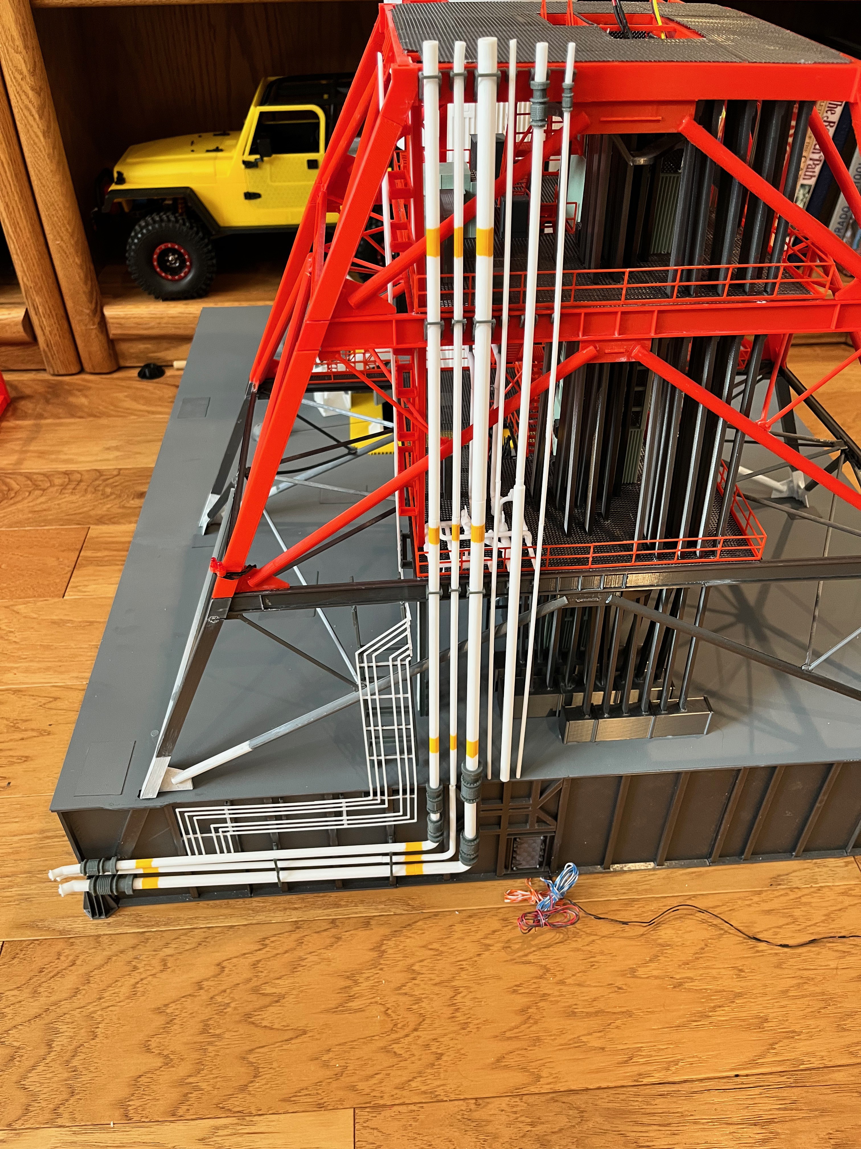
The water pipes are designed, printed, red bands painted and glued in for section #1 of the tower. I did not design in pipe stand-offs because these are small, light and airy. Instead I simply glued them to the I-beams. The first of the ECS pipes are printing. I need to go see if they are complete...

While waiting for parts to print I decided to decode the Aviator67 parts list. This includes getting the color correct in the spreadsheet and account for every part, including missing parts that I want to print. This involved comparing the equipment layout files against the MicroArtwork and Turbosquid files. I started at the bottom and worked up, just like the model is being built. There seemed to be missing files that I later found at higher levels. Sometimes parts are duplicated and in other cases you have to find them at higher levels. Fortunately the equipment parts are numbered, allowing for a search. My spreadsheet has been updated to reflect this effort. I also added the parts for the Amphioux Saturn V model to get a good count of all printed parts to compare against the farscape1 model. The farscape1 model has 2056 parts. Mine is up over 5000 parts and counting.
One thing I considered was modeling the deluge pipes on Side 1 of the tower, but decided not to until at level 260 I found upper and lower deluge pipes from aviator67. There appears to be a pair of these pipes for every swing arm, so about 9 sets. The aviator67 pipes seem to match fairly closely to the first set so I printed and added those. As you go up they are not the same and I will have to build unique parts for these. In the picture below you can just see the pipes. The upper pipe is at about the same level as the railing. The lower pipe is easier to see. I did not attempt to attach these to the water pipe on side 2.

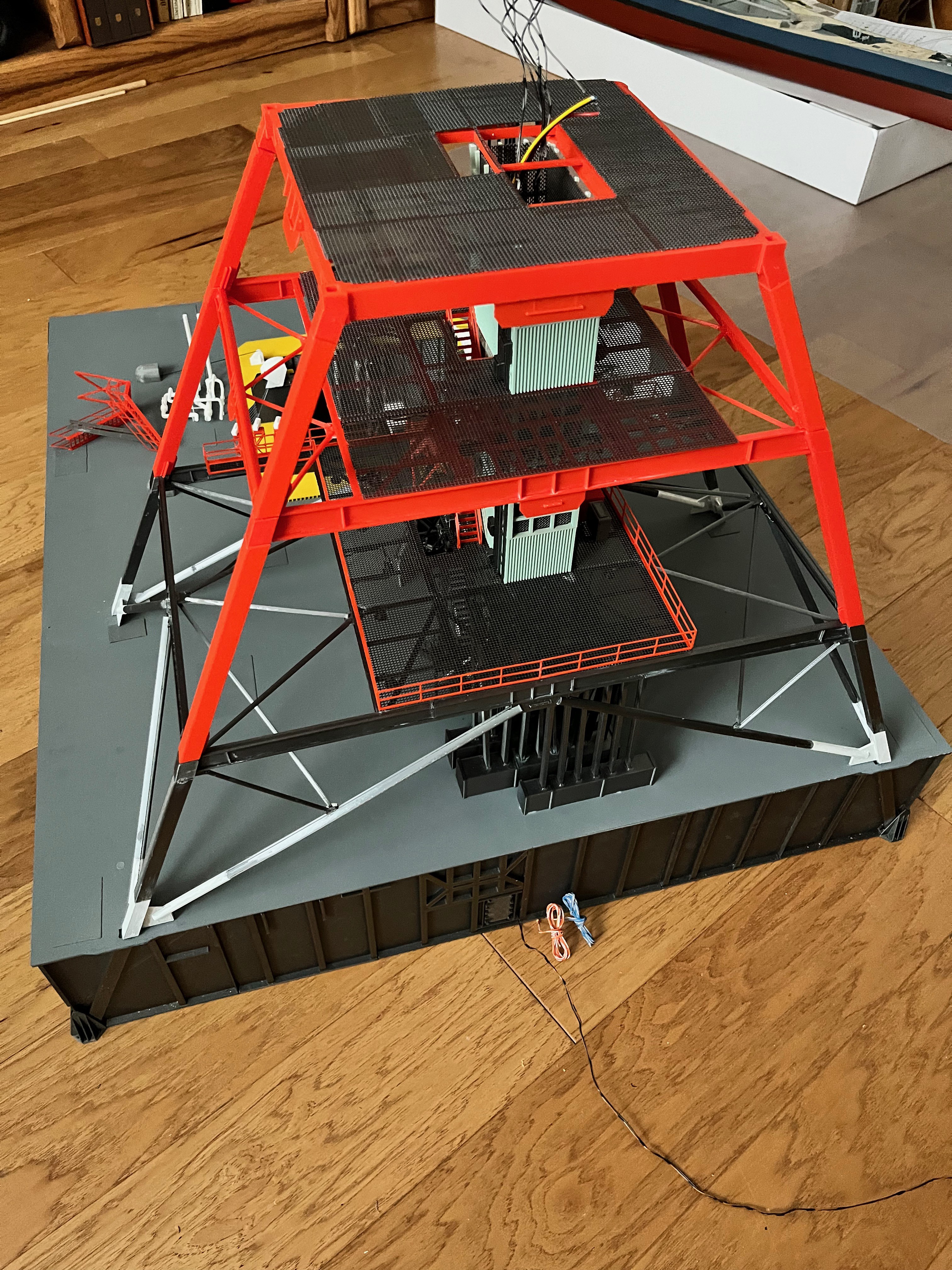
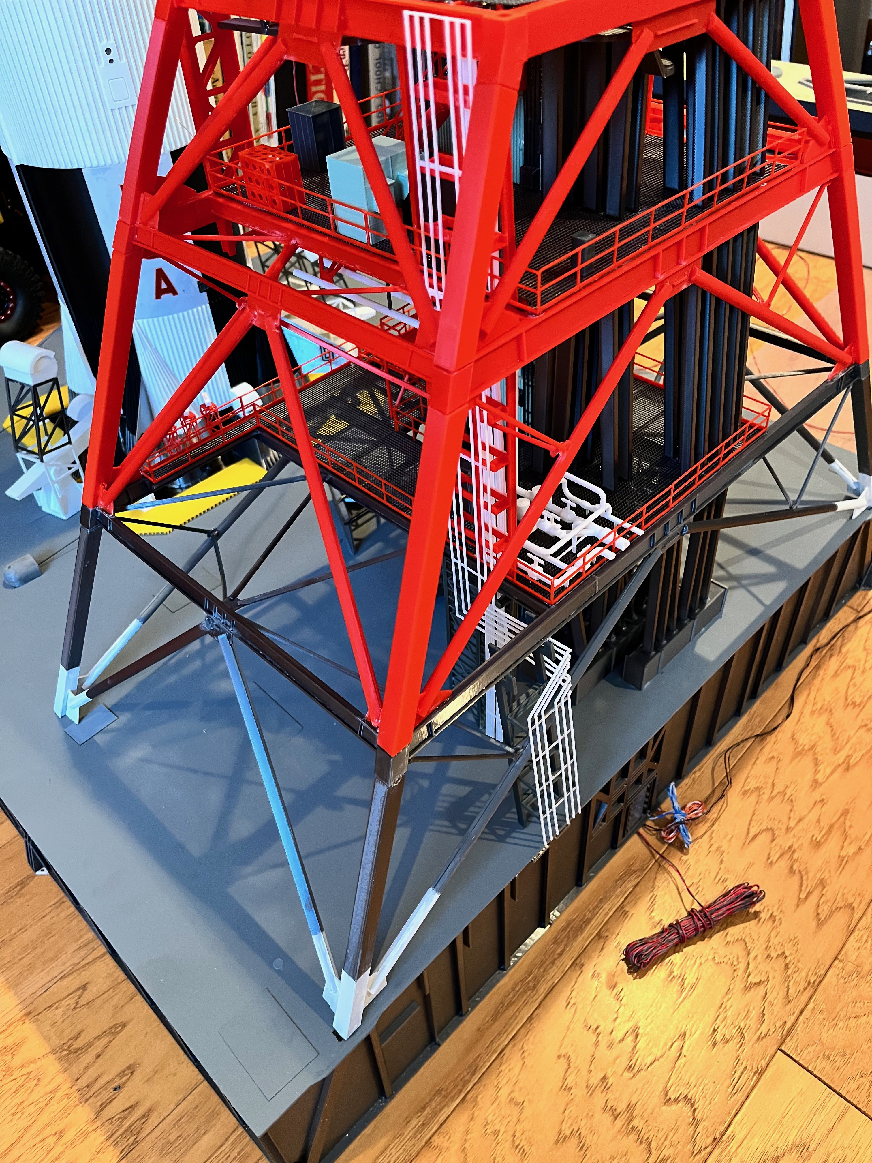
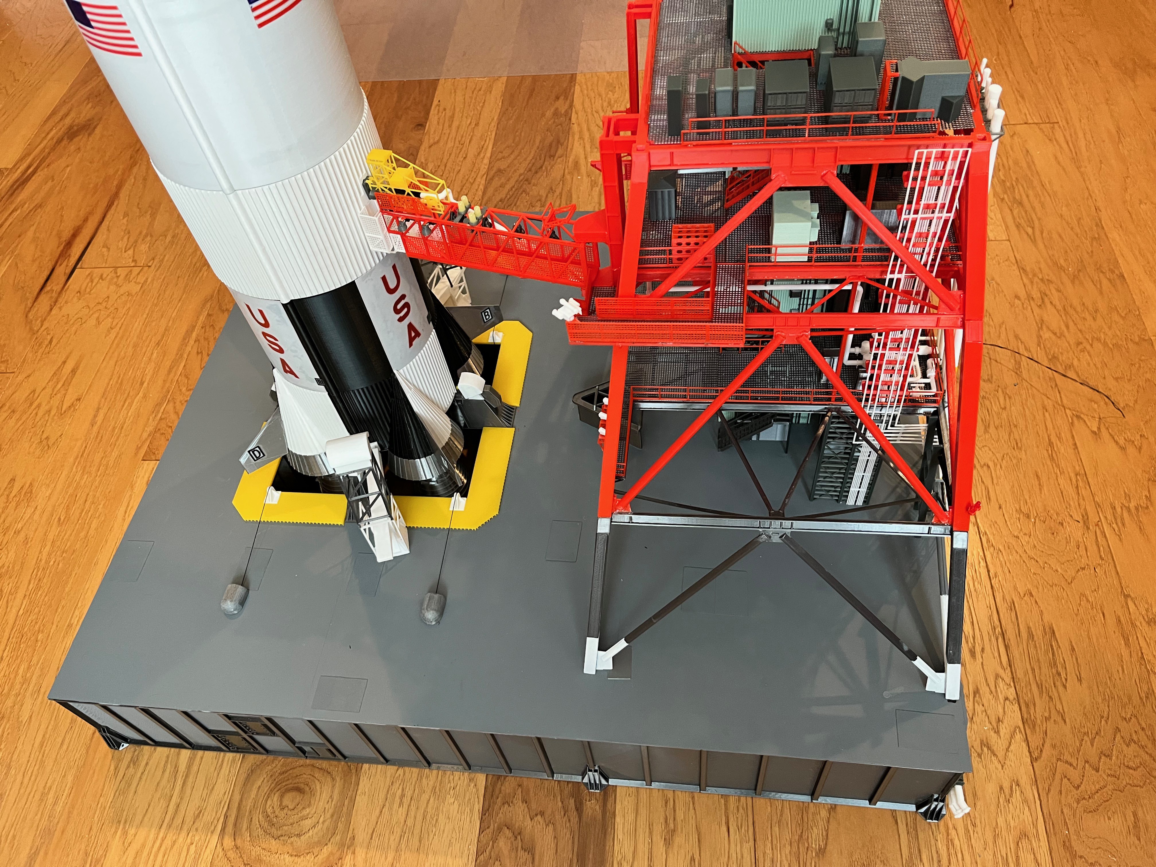
The first section of the tower is now complete! This took quite a while due to all the CAD work that had to be completed. The next section should go much faster, only two levels and no swing arms. This will be a simple matter of verify and printing parts along with a little glue.

Discussions
Become a Hackaday.io Member
Create an account to leave a comment. Already have an account? Log In.