 Bitmerse LLP
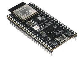
- Based on ESP32-S2 Wi-Fi SoC
- No driver installation required
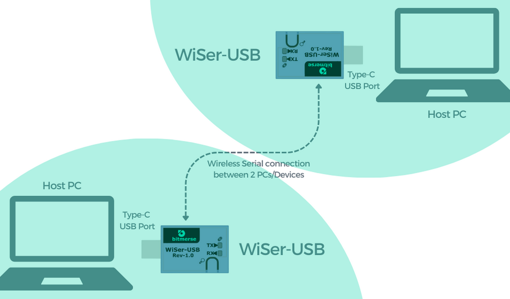
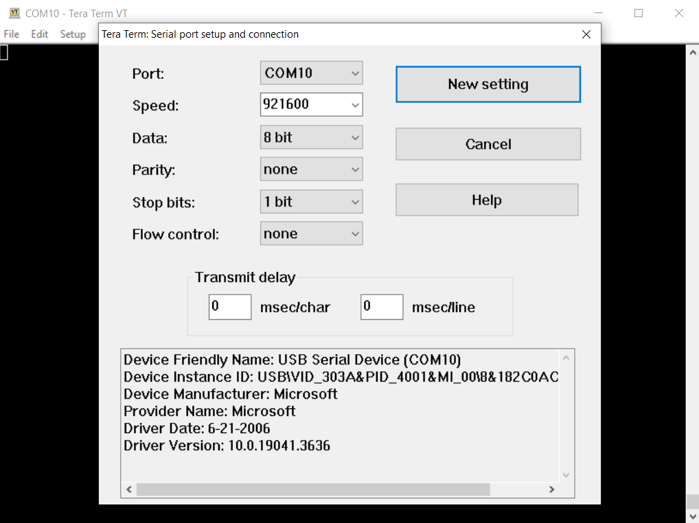
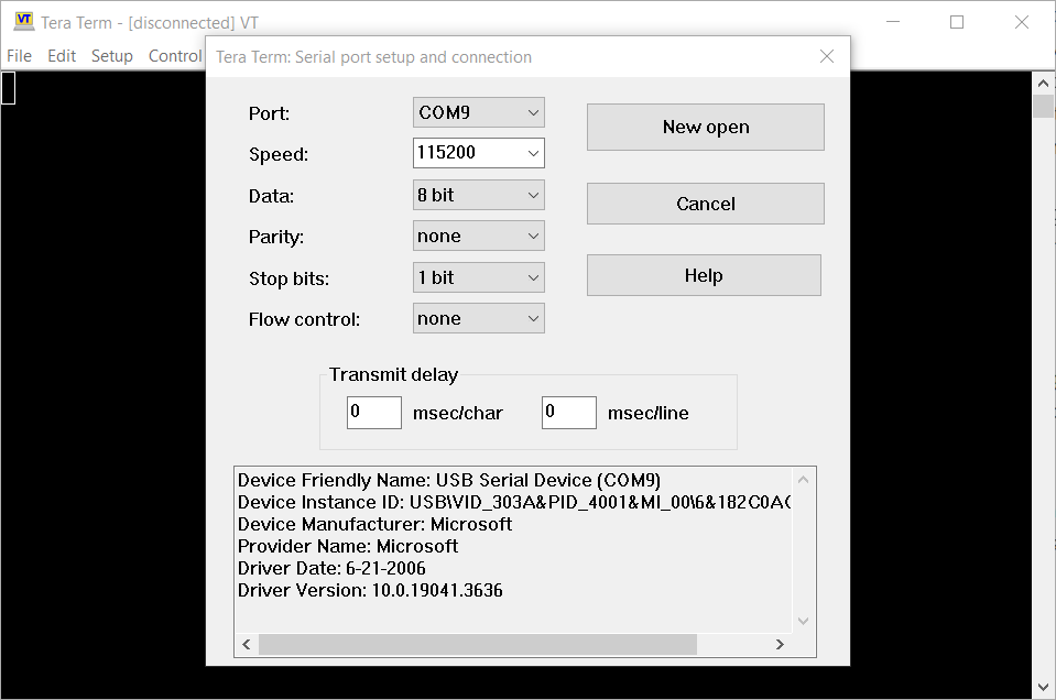
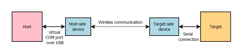
- Provides virtual serial port on host
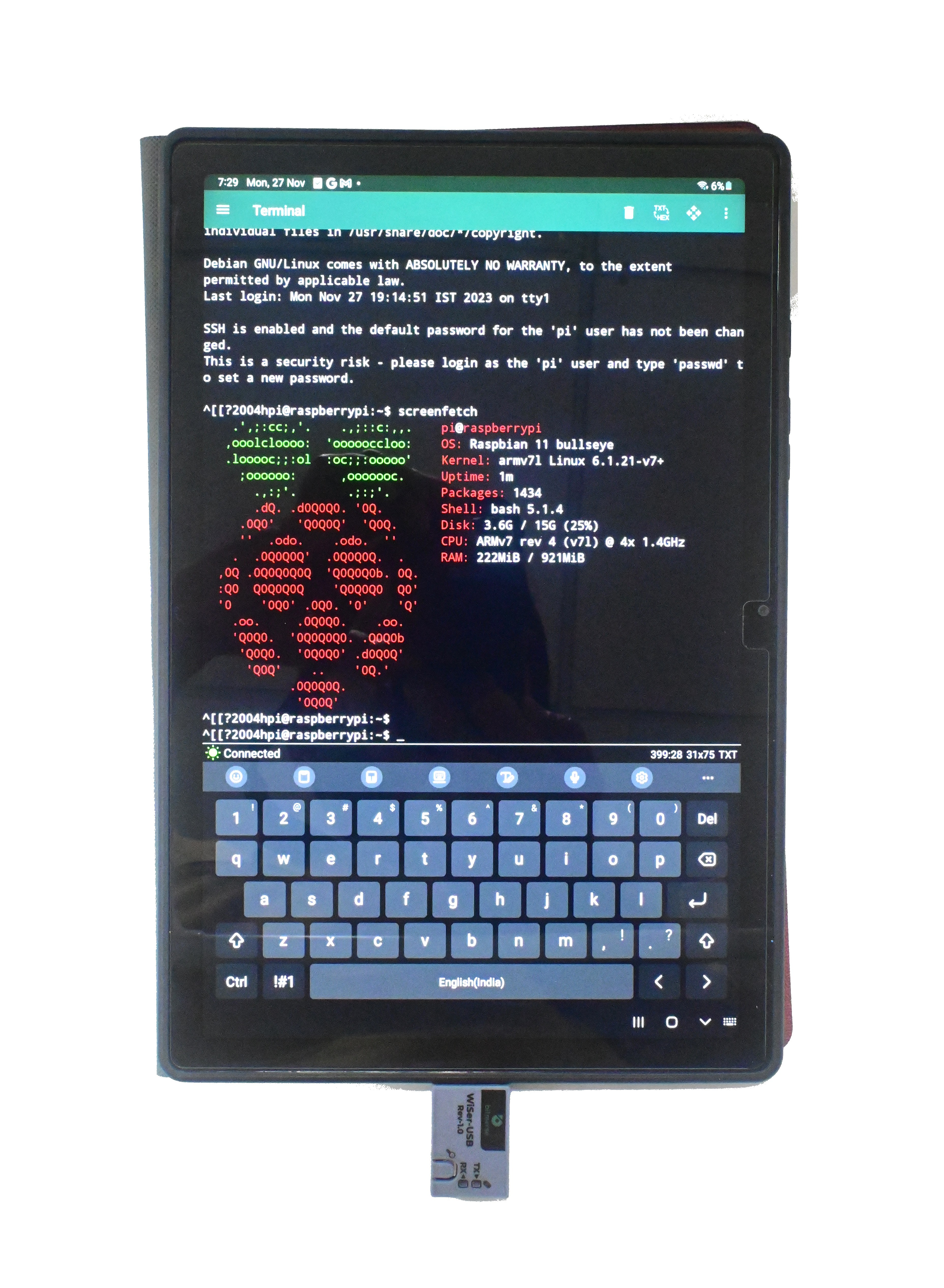
- Targeted for modern devices with USB Type-C ports
- Compatible with Windows, Linux, Mac, and Android
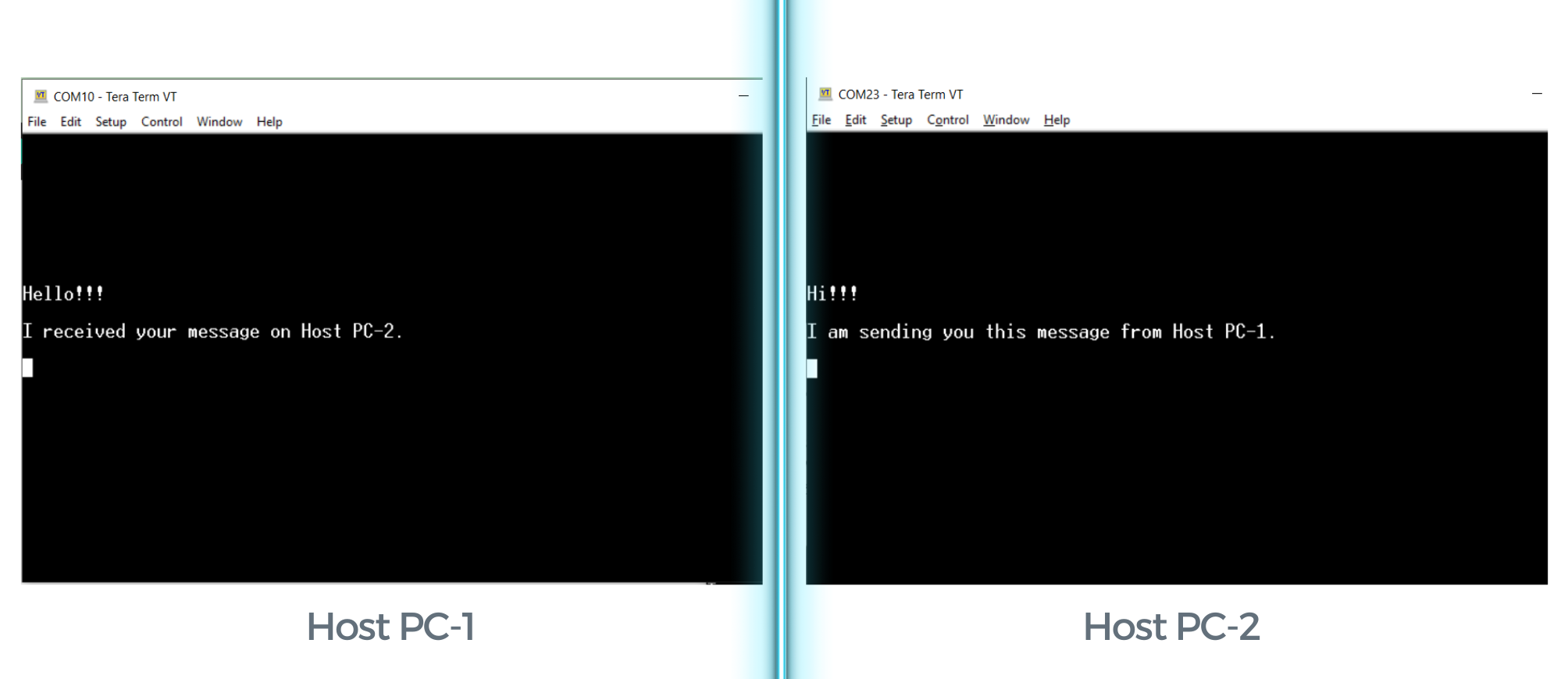
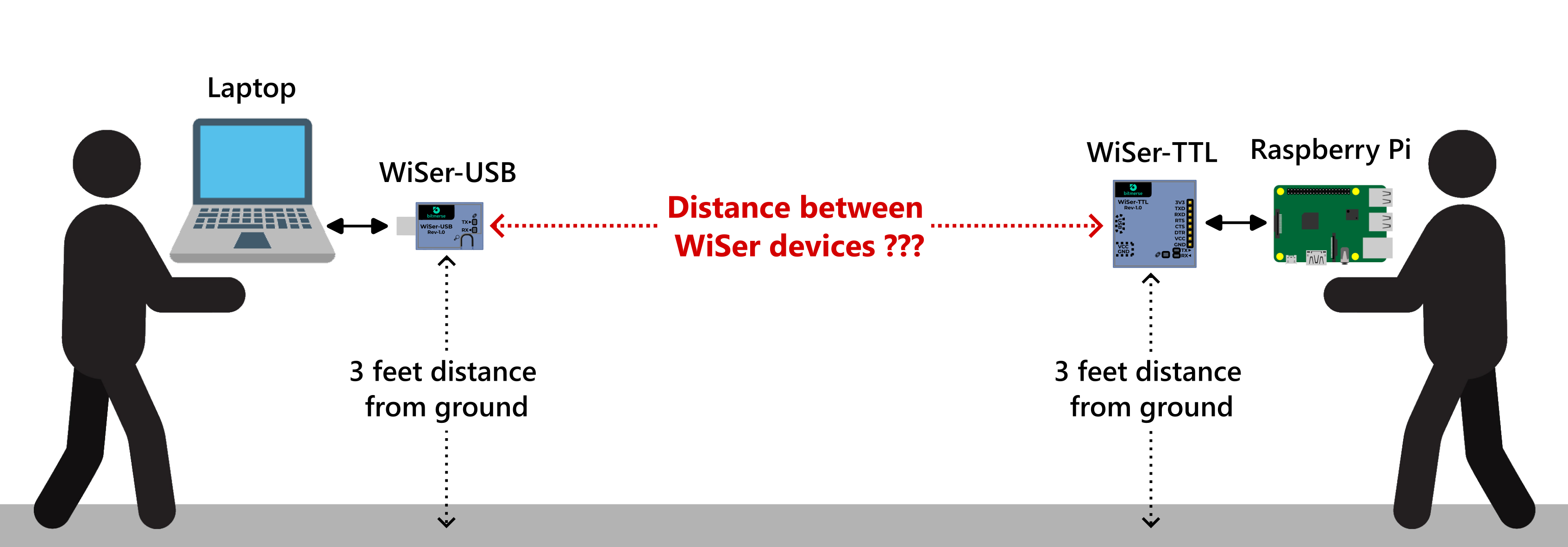
- Peer-to-peer wireless communication over 2.4 GHz
- Data protection using AES-CCMP encryption
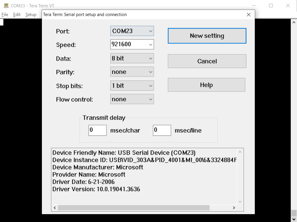
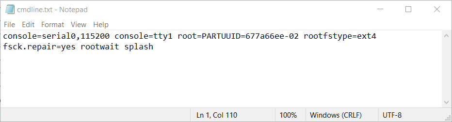
- Supported baud rates: all standard and custom rates up to 921,600 baud
- Supported data bits: 6-bit, 7-bit, 8-bit
- Supported parity types: NONE, ODD, EVEN, MARK, and SPACE
- Supported stop bits: 1-bit, 1.5-bit, 2-bit
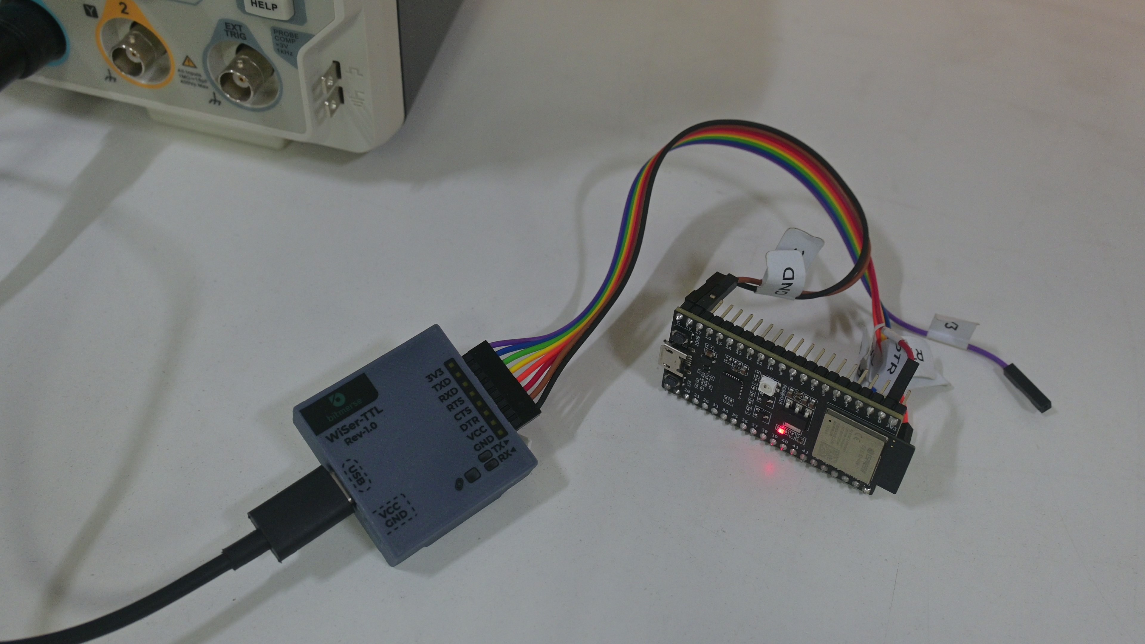
- Supported flow control: software (XON/XOFF), hardware (RTS/CTS), and None
- Equipped with DTR control pin
- RX, TX, and CONN indicator LEDs
- "FIND PAIR" button to locate the paired device (useful when deploying multiple WiSer devices)
- "BOOT" button to update ESP32-S2 firmware
- Fully open-source
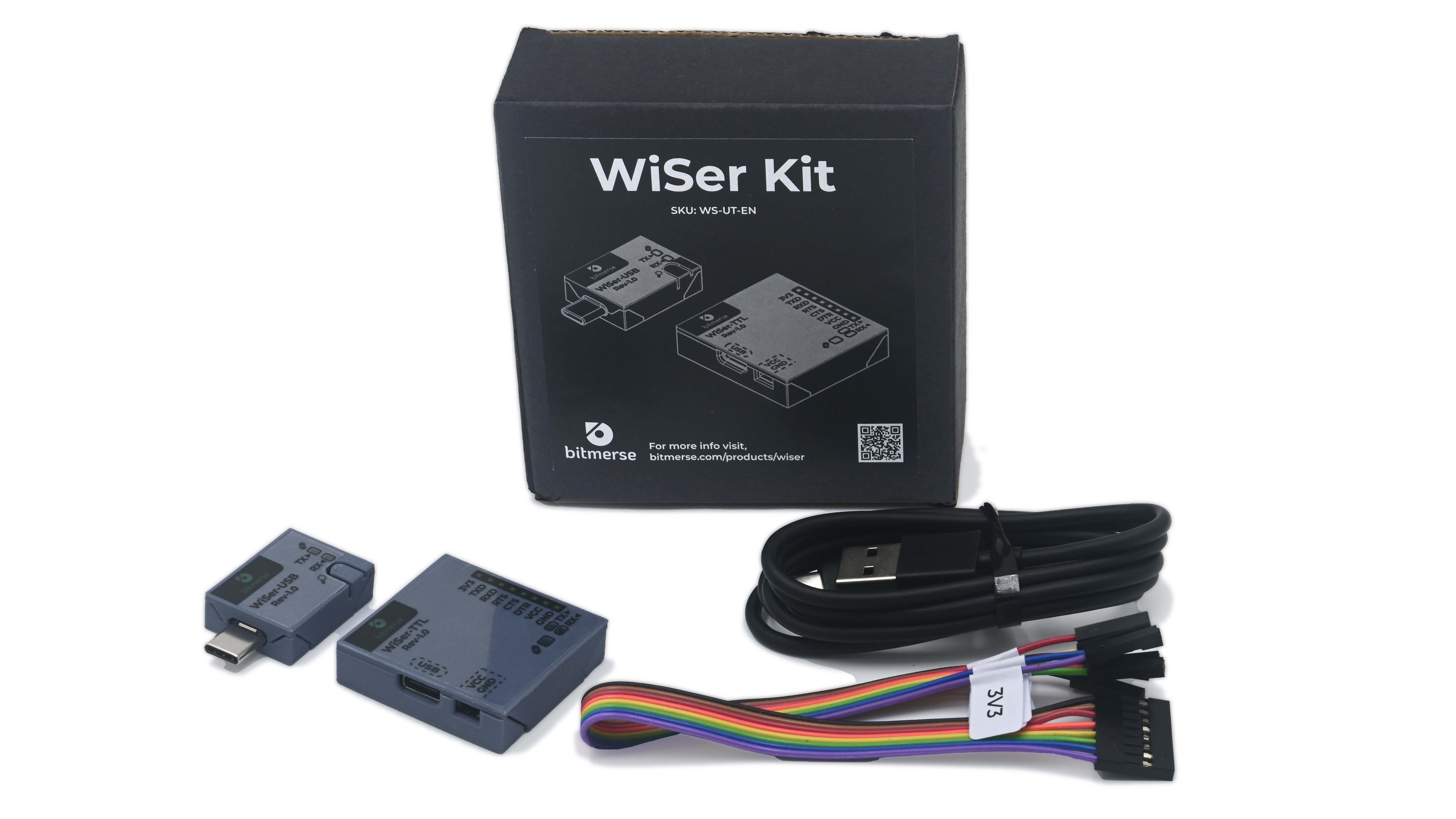
- Physical dimensions
- WiSer-USB: 37.8 x 20.4 x 8.2 mm
- WiSer-TTL: 36.5 x 38.4 x 9.8 mm
0%
0%
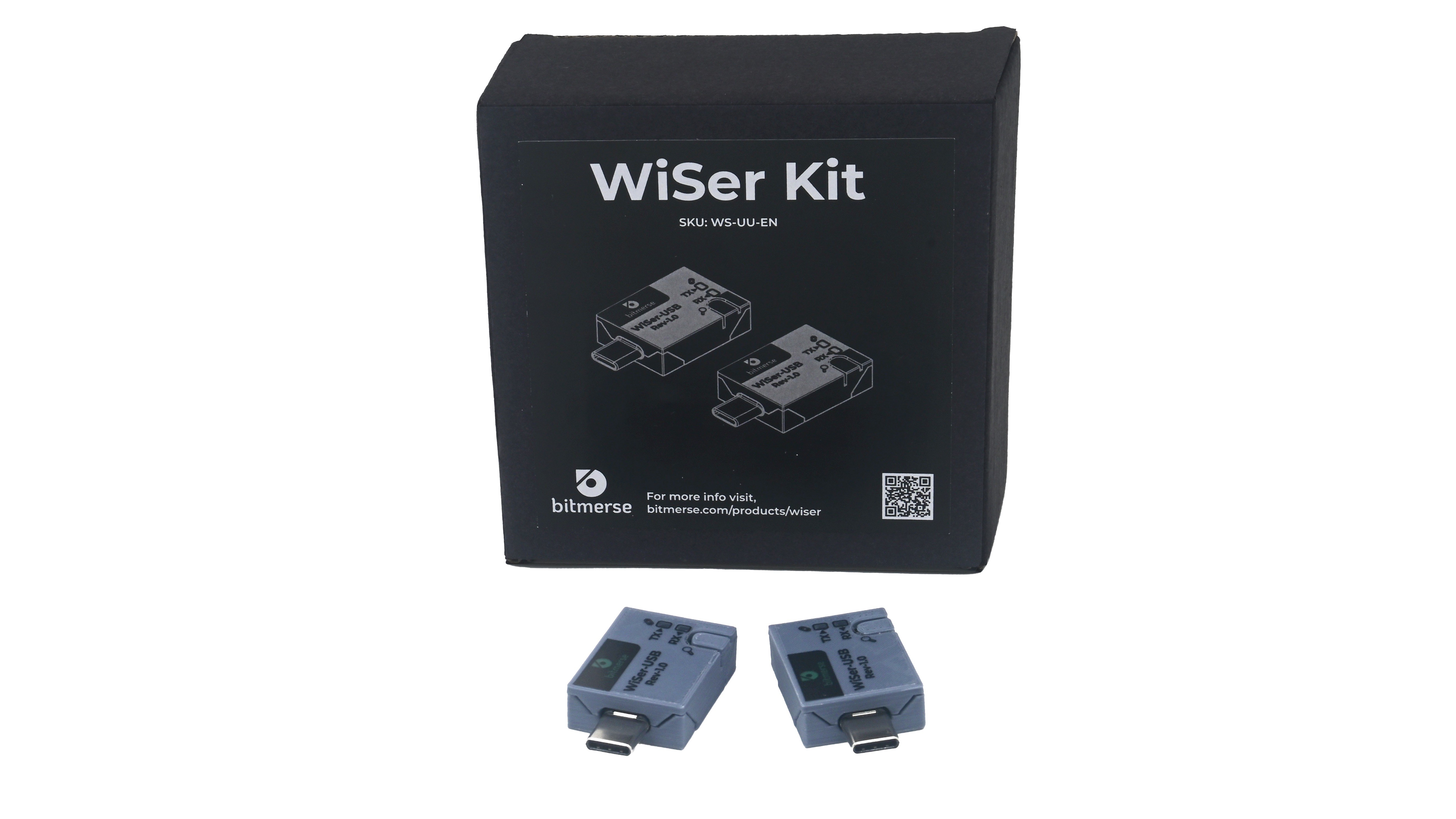
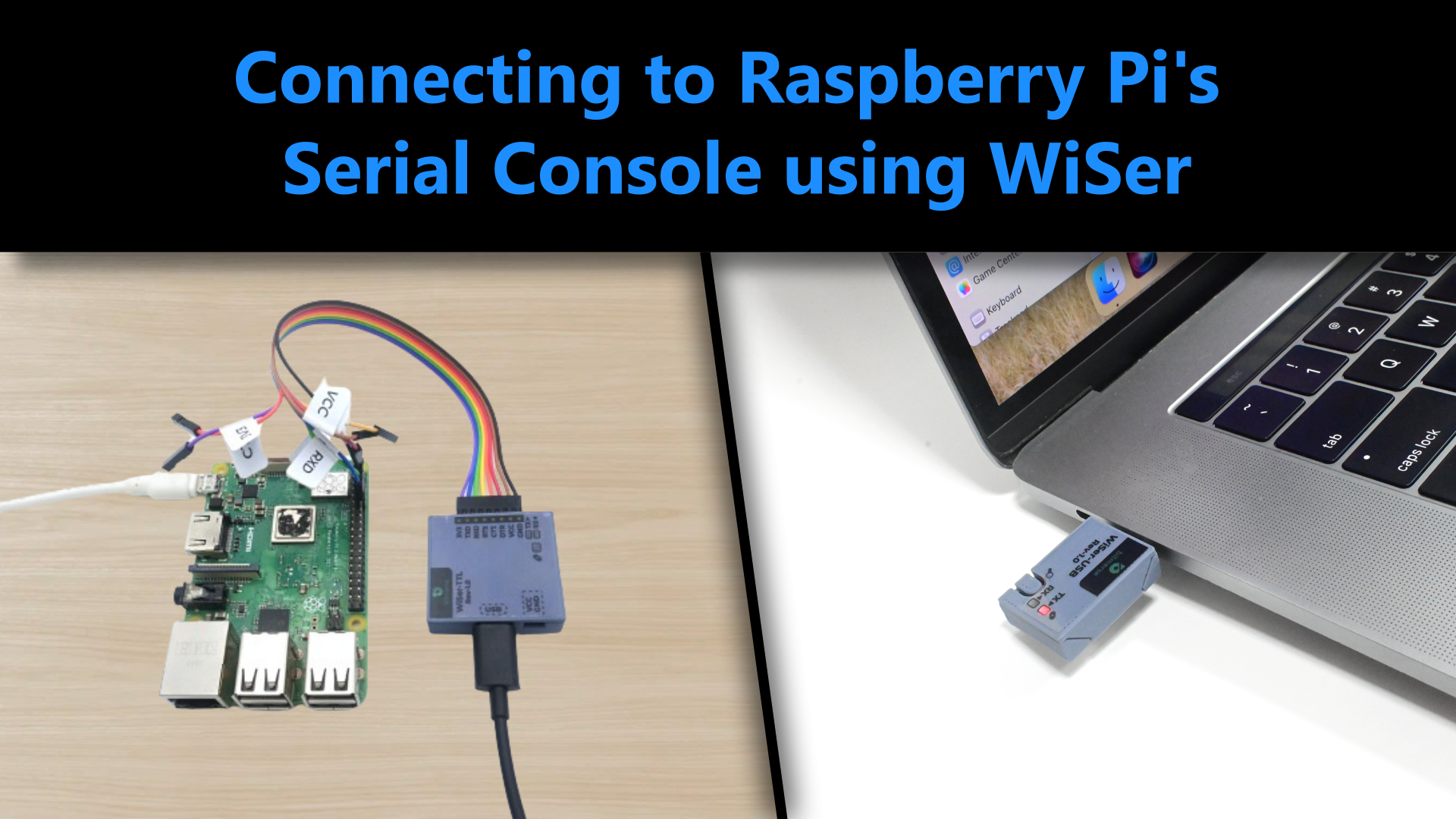
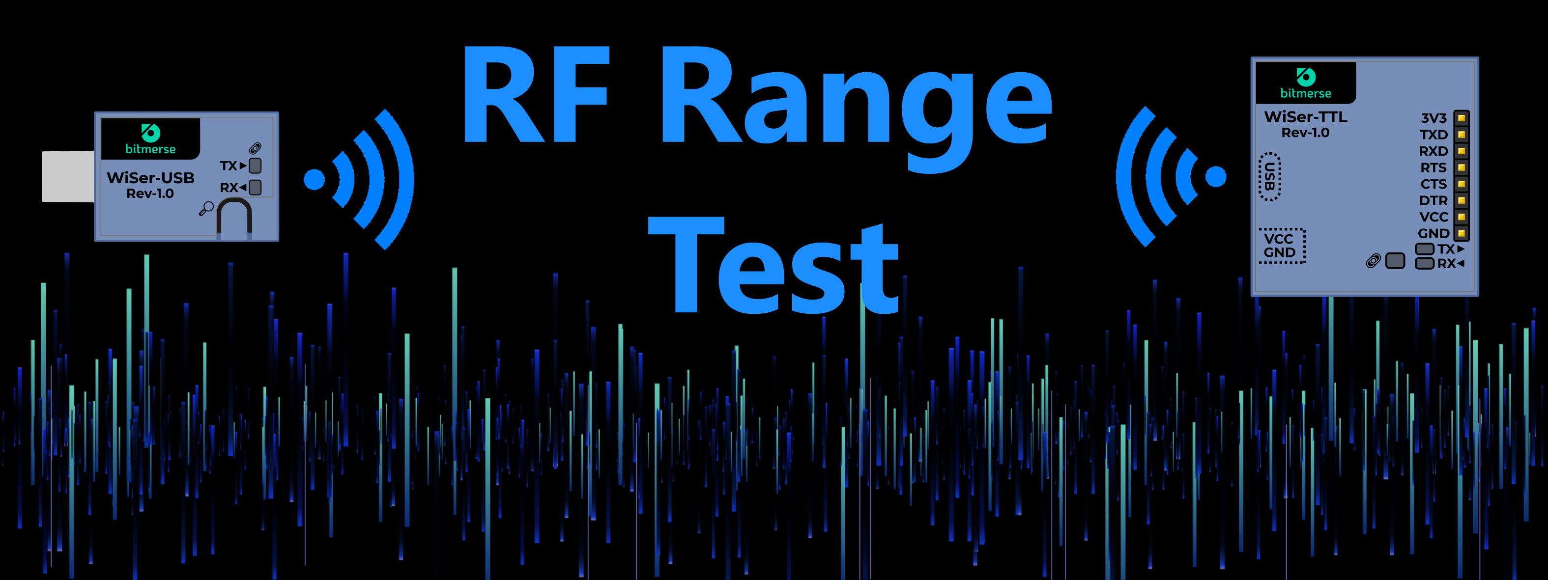
WiSer
Bringing wireless convenience to serial connectivity
Become a Hackaday.io member
Already have an account? Log in.
Just one more thing
To make the experience fit your profile, pick a username and tell us what interests you.
Pick an awesome username
hackaday.io/
Your profile's URL: hackaday.io/username. Max 25 alphanumeric characters.
Pick a few interests
Projects that share your interests
People that share your interests


 Amit
Amit
 Stefan Wagner
 CarbonCycle
 Gavin169
Seems like a well thought-through project. ESP32-S2 is good choice w/ built-in USB support. and ESP-NOW Looking forward to the campaign. Curious about two things.
1. What all went into the design and verification of your RF section? Always seems that this is difficult part for small and [probably] boot-strapped teams.
2. Have you used your board to remotely program another ESP32 using RTS# and DTR# to automatically enter boot mode of the remote device via the typical 2-NPN transistor circuit for EN and IO0)? I ask since the timing of those signals is important in this case.