Components required to build a Class D audio amplifier circuit
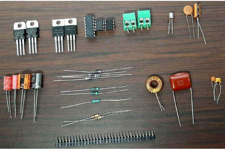
Parts list for building a Class D power amplifier (available at Avaq):
IR2110 integrated circuit - 1
Lm358 Op Amp - 1
NE555 timer IC - 1
LM7812 integrated circuit - 1
LM7805 integrated circuit - 1
102 pF capacitor - 1
103 pF capacitor - 1
104 pF capacitor - 2
105 pF capacitor - 1
224 pF capacitor - 1
22uF capacitor - 1
470uF capacitor - 1
220uF capacitor - 1
100uF capacitor - 2
2.2K resistor - 1
10K resistor - 2
10R resistor - 2
3.5mm audio jack - 1
5.08 mm screw terminal - 2
UF4007 Diode - 3
IRF640 MOSFET - 2
10K Decorative Pot - 1
26uH inductor - 1
3.5mm headphone jack - 1
Class D amplifier circuit schematic diagram

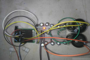
Building a circuit on PerfBoard
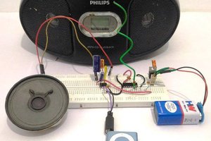
As you can see from the main picture, we made the circuit on a piece of perfboard. Because, firstly the circuit is very simple and secondly if something goes wrong we can modify it quickly and easily. We made most of the connections with the help of copper wires, but at some final stages we had to use some connecting wires to complete the build. The completed perforated board circuit is shown below.

Input voltage regulator:

We first regulate the input voltage using a 5V regulator LM7805 and a 12V regulator LM7812. This is important because we are powering the circuit with a 13.5V DC adapter, and to power the NE555 and IR2110 ICs, 5V and 12V supplies are required.
Triangular wave generator with 555 astable multivibrator:

As you can see from the picture above, we used a 555 timer with a 2.2K resistor to generate a 260KHz triangle signal. If you want to know more about Astable Multivibrator, you can check out our previous article on 555 Timer Based Astable Multivibrator post circuit where we have described all the necessary calculations.
Testing Class D Amplifier Circuits

As you can see from the picture above, I used a 12V power adapter to power the circuit. Since I'm using an affordable Chinese product, it puts out a slightly higher voltage than 12V, 13.5V to be exact, which is perfect for our onboard LM7812 voltage regulator. As a load, I used a 4 ohm, 5 watt speaker. For audio input, I use a laptop with a 3.5mm long audio jack.
When the circuit is powered there is no noticeable buzz like other types of amps, but as you can see in the video the circuit is not perfect and clipping occurs at higher input levels problem, so this circuit has a lot of room for improvement. The MOSFET didn't get hot at all when I drove moderately low loads, so for these tests it didn't need any heatsink.
This class D power amplifier circuit is a simple prototype with a lot of room for improvement. The main problem with my circuit is the sampling technology, which needs improvement. To reduce amplifier clipping, appropriate inductor and capacitor values need to be calculated to obtain a perfect low-pass filter stage. As always, the circuit can be made on the PCB for better performance. A protection circuit can be added to protect the circuit from overheating or short circuiting.

 Electroniclovers123
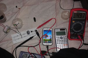
 UTSOURCE
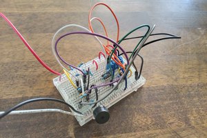
Is there any point to this, other than pedagogic, when there are off the shelf chips can amplify as well as handle bluetooth and USB input, and complete boards are under $10?