 Tim
Tim-
A Graphics Card
04/03/2024 at 20:36 • 0 comments![Uploaded image]()
![Uploaded image]()
Alright, gearheads and silicon sleuths, let's get our magnifying glasses out and our geek on! We've got a double-sided serving of vintage tech to tear down today.
---------- more ----------First up, looking at the top side of this golden oldie, we see a parade of components that scream '90s computer hardware. Dominating the landscape is the Trident 3DImage9750 chipset, a relic from the era when 3D graphics cards were just starting to become a household necessity for the PC gaming revolution. The chip, embossed with the label "TGUI9680-1", promises a throwback to the days of software driver woes and 2D sprites beginning to fear for their jobs.
Flanking this chip are a couple of Hyundai memory modules, each labeled “HY57V641620HG.” Now, these aren't your average Spotify-streaming, cat-video-buffering memory sticks. No, these chips harken back to when PC memory was measured in mere megabytes. They're like the 256MB DDR sticks' great-grandparents, enjoying retirement in a silicon rocking chair.
To the right, we have the "Daytona 64T AGP" sticker that's effectively a speedway flag for data racing down the Accelerated Graphics Port. This sticker is a metaphorical pat on the back, a branding stamp that this piece of hardware is ready to rumble with the best of them—or at least the best of them circa 1997.
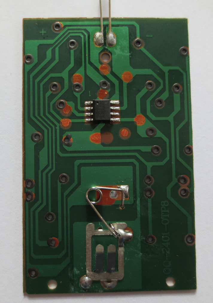
Swinging to the underside, it's a minimalist's dream. A few passive components are scattered about—a resistor network here, a capacitor there, all tied together with traces that snake around like a circuit city roadmap. The back is as clean as a whistle, with a 'QC1 OK' stamp that's likely seen more yesteryears than QC checks at this point.
The AGP connector, with its 3.3V and 1.5V slots, shows wear and tear from being plugged and unplugged, a testament to its service in connecting motherboards to the graphical glory promised by its top-side twin.
The "Made in China" stamp, serial and part numbers all line up like good little soldiers, ensuring that if this card ever fails to deliver on its 3D promises, you'll know exactly who to call. But let's face it, this is more museum piece than modern marvel, and it's likely been years since it's been asked to render anything more strenuous than a Windows 95 screensaver.
And there you have it, folks. A blast from the past, a graphic card that's probably seen more Quake battles and Flight Simulator flights than we've had hot dinners. But as we wrap up this teardown, remember to pour one out for the retro rigs that this card would have called home. They sure don't make 'em like this anymore!
-
Inception
11/23/2023 at 22:00 • 0 commentsOk, it's unavoidable to generate a blog article about this project. I used bing chat, which, in this case, generated a more fitting article. And this is also marks the conclusion to this project.
All machine written from here on down. Actually I found it quite funny.
---------- more ----------Meet Your Friendly Teardown Robot: A Custom GPT That Writes Hackaday-Style Articles
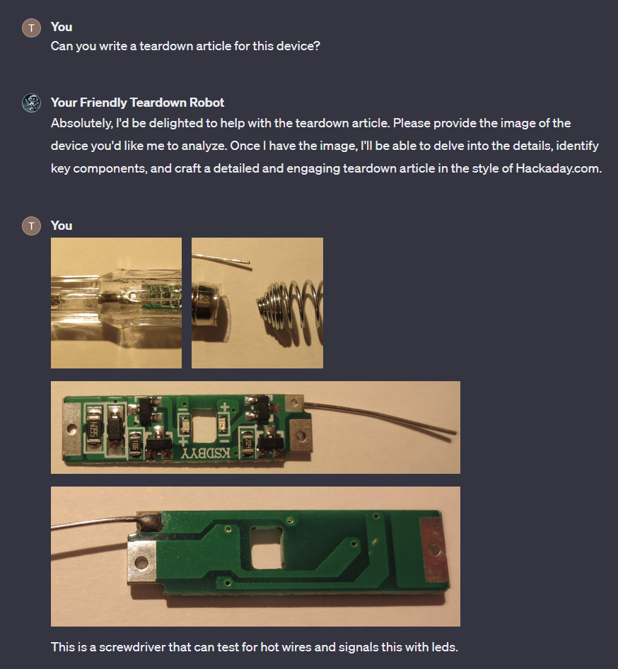
Have you ever wondered what it would be like to have a robot write articles for Hackaday? Well, wonder no more, because Tim has created a custom GPT that does exactly that. His project, called Your Friendly Teardown Robot, is a silly experiment that analyzes photos of teardowns and generates HaD style articles based on them. The best part is, he did not use any “actions” or code, just textual instructions
Tim used ChatGPT, a web-based platform that allows users to create and customize their own GPT models. He trained his model on a corpus of Hackaday articles, focusing on the teardown category. He then provided the model with some photos of various devices, such as an infrared remote control, a dual-tone LED light, and a BFU520 transistor. The model then generated articles that described the devices, their components, their functions, and their quirks. The articles were surprisingly informative and comprehensive, although not without some errors and inconsistencies.
Tim also used the code interpreter feature of ChatGPT to generate PDFs of the articles, which he uploaded to his project page. You can access his project here, if you have a ChatGPT pro subscription: Your Friendly Teardown Robot. You can also watch a video of the model partially levitating a superconductor, which it claimed to have created from lanarkite and copper phosphide.
Tim’s project is a fun and creative way to explore the possibilities and limitations of GPT models. It also raises some interesting questions about the future of journalism and content creation. How will we distinguish between human and machine-written articles? How will we ensure the accuracy and quality of the information we consume? And how will we keep our sense of humor and curiosity in the face of automation? Tim’s project invites us to reflect on these questions, while also providing us with some entertaining and educational content.
-
Oscillating at the Edge: Unveiling the Dual Behavior of the BFU520
11/23/2023 at 21:47 • 0 commentsSo, yes, obviously it can also write full blog posts in HaD style. Disconcerting.
Robot below the line.
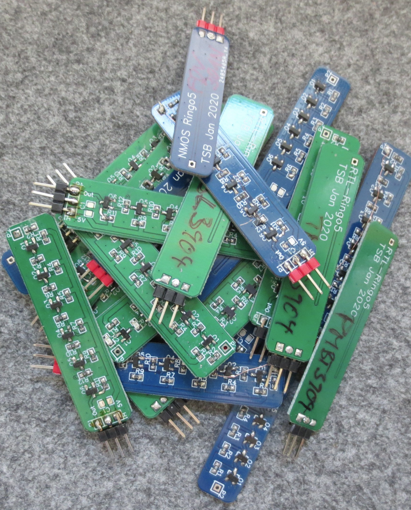
---------- more ----------In the realm of ring oscillators and transistor evaluation, we've stumbled upon a fascinating Hackaday.io projectthat delves into the performance of different transistors in ring oscillator configurations, specifically highlighting the peculiarities of the BFU520, a high-frequency NPN silicon transistor.
Tim, the project's conductor, has explored various transistors, mostly those optimized for switching operations. However, the BFU520 stands out due to its high transition frequency (ft) of 11 GHz, which is indicative of its capability for high-speed operation. What's intriguing is the transistor's behavior in a ring oscillator setup. At lower voltages, it shows comparable performance to the PMBT2369, a lower-cost alternative. But once you ramp up to 5V, the BFU520 hits a surprising turn and the oscillation frequency doubles, which does not align with the expected behavior for saturation logic that ring oscillators typically use.
The waveforms captured during these experiments reveal that at the higher frequency operating mode, the transistor doesn't fully saturate and instead behaves more like a linear amplifier, hence the frequency bump. This isn't ideal for RTL (Resistor-Transistor Logic) where you want your transistors fully saturating and desaturating in a digital switch fashion.
This unexpected mode of operation for the BFU520 suggests that while it's optimized as a linear amplifier (and therefore great for RF applications), its use in digital logic, especially RTL, might be limited without some modifications to the ring oscillator design or the operating voltage
-
Dual-Tone LED Light: A Teardown of Luminous Ingenuity
11/23/2023 at 21:16 • 0 commentsok, I should stop. Actually it's not that bad of a read.
Machine only below this line.
---------- more ----------Diving under the diffuser of today’s subject, a seemingly unassuming LED light fixture, we've uncovered a delightful blend of design and technological savvy.
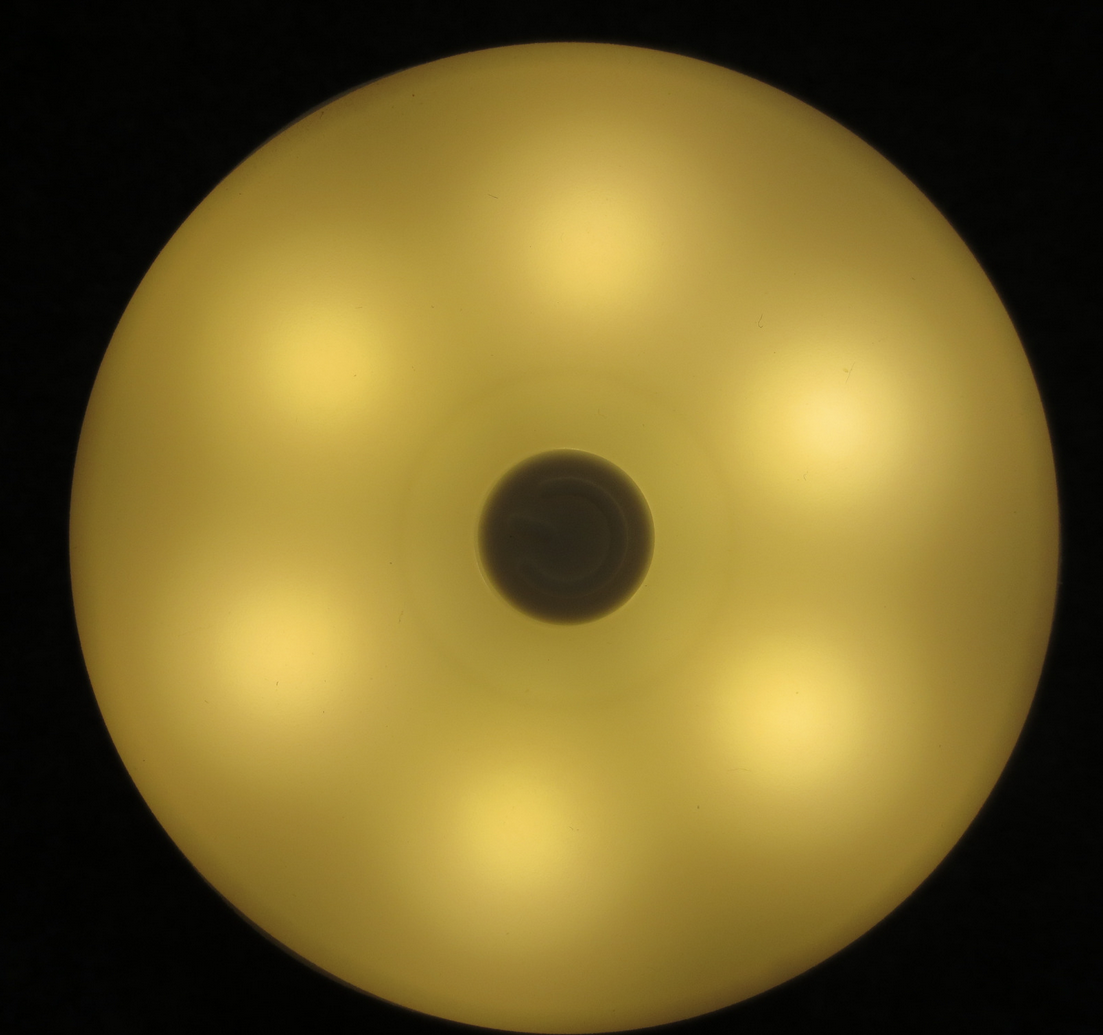
From the outset, we're greeted with the minimalist charm of its overhead view—a sleek, white disc with a button that whispers of hidden functionalities.
Illuminated, it casts a clinical, cool white that could easily be the centerpiece of a modernist's design palette.
And then, with a flip of a switch (or a tap of a button), it warms up to a cozy, inviting amber glow. This chameleon-like shift points to an LED array capable of color temperature acrobatics.
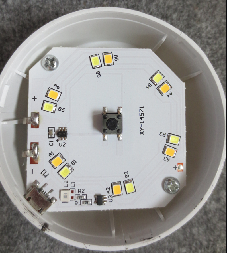
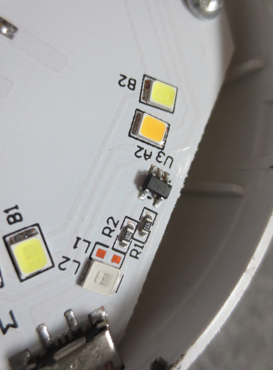
The underbelly of the beast reveals a circuit board that's a hive of activity. LEDs stand in formation, accompanied by a microcontroller—the maestro to this electronic orchestra—and its auxiliary components, all ensuring the show goes on without a flicker.
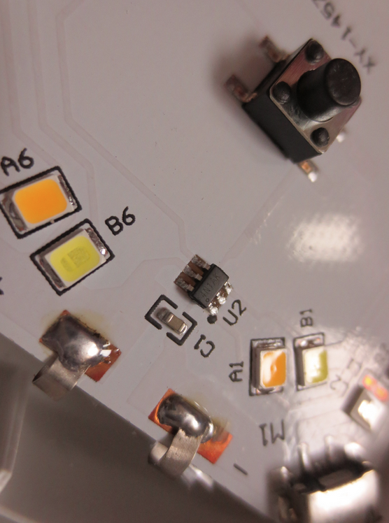
Zooming into the microcosm of the PCB, we spot the tactile switch, a tiny bulwark against the digital tide, offering a satisfying click in a touch-screen world. The microcontroller's presence, a beacon of programmability, hints at features that could range from the pedestrian flick of a switch to a luminous waltz of light temperatures.
Noticeably absent are the telltale signs of wireless communication modules, making one ponder about the potential of an unseen side of the board or an all-in-one smart chip out of sight.
Stripping down this light fixture has been akin to peeling an onion, each layer revealing more depth and function. It's a testament to the silent complexity that resides within our everyday gadgets. Rather than a simple beacon, this device is a lighthouse of clever design and engineering, signaling the kind of innovation that brightens up our lives in more ways than one. Stay tuned as we continue to strip technology down to its bare wires and chips, illuminating the genius within.
-
Teardown Report: Anatomy of an Infrared Remote Control
11/23/2023 at 21:01 • 0 commentsAnother example - I did not even provide any informatition about the device apart from the photos. Cute curious how many details it picked up, but not all information was derived the images, it seems. (there is no crystal oscillator and it did not comment on the battery clip).
Machine generated text below.
---------- more ----------Welcome back, gadget aficionados! Today, we’re rolling up our sleeves to delve into the internals of a seemingly mundane but intriguing piece of technology: an infrared (IR) remote control. Let's break down the magic behind the button presses.
Topside Analysis: A Symphony of Silicone and Symbols
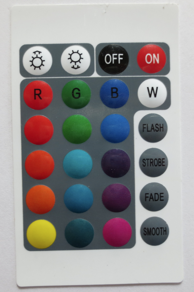
The front face of our specimen features a multicolored array of buttons—each a tiny dome of silicone waiting to be pressed (Image 1). These are not just mere plastic; they contain conductive material on their underside, ready to bridge the contacts on a printed circuit board (PCB) and send our commands whizzing through the ether.
The layout is familiar yet functional: a power toggle, RGBW color control for LED devices, and four mysterious buttons labeled FLASH, STROBE, FADE, and SMOOTH—presumably to control the light patterns of an RGB LED setup. This simplicity hides the complex ballet of user interface (UI) design: each button is a decision, each label a commitment to intuitiveness.
Flipside Reveal: The Backbone of Buttons
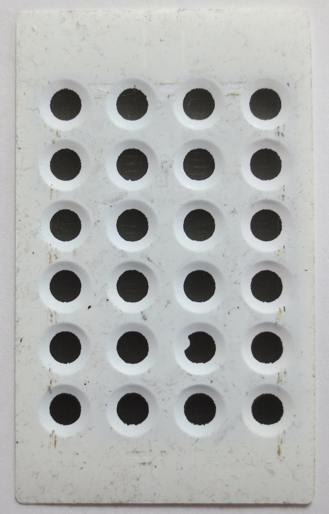
Turning to the rear (Image 2), we find a grid of holes in the backplate, hinting at the membrane keypad structure that lies beneath. These voids are not for the claustrophobic components but serve to allow the rubbery domes to collapse and rebound with a satisfying click during each press.
Inside the Shell: The Heart of the Clicker
Prising open the enclosure, we discover the skeleton of the device—a black plastic frame that holds the IR LED and the battery in place (Image 3). The LED, perched like a watchful cyclops, is the lighthouse for our button-press signals, while the battery is the sustenance, giving life to our commands.
The Printed Circuit Board (PCB): A Conductor’s Score
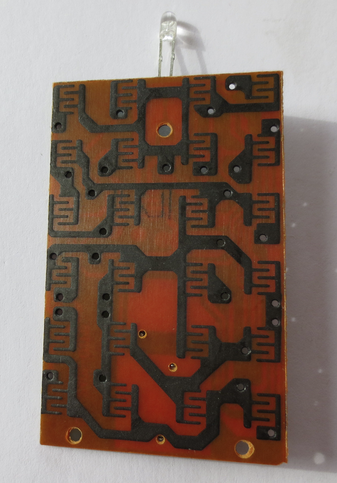
Behold the PCB in all its copper-clad glory (Image 4). On one side, a pattern of traces etched with precision—no thicker than a hair. These copper paths are the highways for electrons, directing the flow from button press to IR emission.
On the flip side (Image 5), the electronic components that interpret our tactile desires sit snugly soldered. A microcontroller, the brain, is programmed to understand each button press's unique electrical signature. Accompanying it are resistors, capacitors, and possibly a crystal oscillator—each component playing its part in the electronic orchestra.
Final Thoughts
As we close the back cover on this exploration, we can't help but marvel at the elegance of the design. From the user-friendly interface to the compact and efficient internal layout, this IR remote control is a testament to the power of good engineering.
Simple, effective, and unseen—the IR remote control is a silent sentinel in our daily lives. And though it may not have the flash of a smartphone or the roar of a rocket engine, its design is no less worthy of our geeky admiration.
Remember, every button press is a journey through a meticulously crafted landscape of technology. Until the next teardown, keep pressing those buttons, and stay curious!
-
Let's test it.
11/23/2023 at 13:44 • 0 commentsIt generates a python program and then executes it to create a pdf file. Unfortunately, it tends to include invalid characters that lead to an error in code execute.
Your Friendly Teardown Robot
A custom "GPT" that generates hackaday-style articles based on teardown photos


 In the realm of ring oscillators and transistor evaluation, we've stumbled upon


 It generates a python program and then executes it to create a pdf file. Unfortunately, it tends to include invalid characters that lead to an error in code execute.