JP Gleyzes
The idea
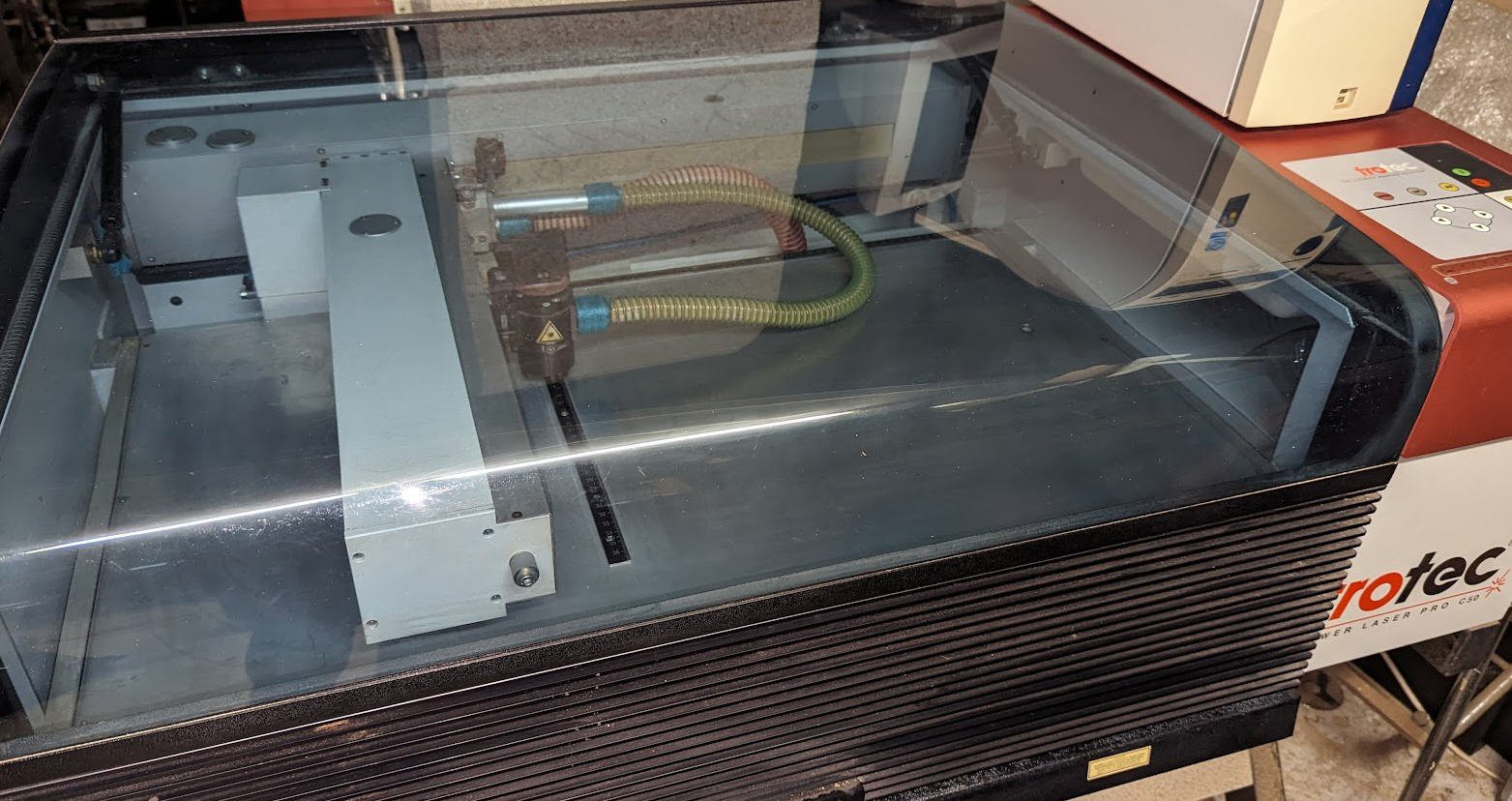
I have an old Trotec laser engraver. It was built in 1998 and worked quite well until this summer 2023. So I would say that it was a very reliable machine but it now suffers from its old age:
- laser tube is dead
- software is very very old fashioned and runs (tries to run) under windows 95 operating system
So it was time to trash this machine... But it looked so professionnal that I decided to refurbish it with more modern electronics.
- As I am an hobbyist I couldn't afford to buy a new RF laser tube, so I decided to change it to a cheap 40W CO2 tube
- As I love ESP32 and micro controllers I decided as well to design my own controller boards based on GRBL FluidNC software.
Follow this project to see how all this can work as expected !
The control board
I was tempted to reuse the original control board. But without any schematics and with the "windows95 concern" I didn't do it.
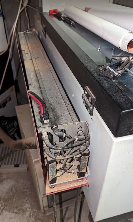
The main board is complex. We can isolate the 4 servo motors controllers on top, the power supplies (30V and 220V relays) on the right and the CPU on the small left board.
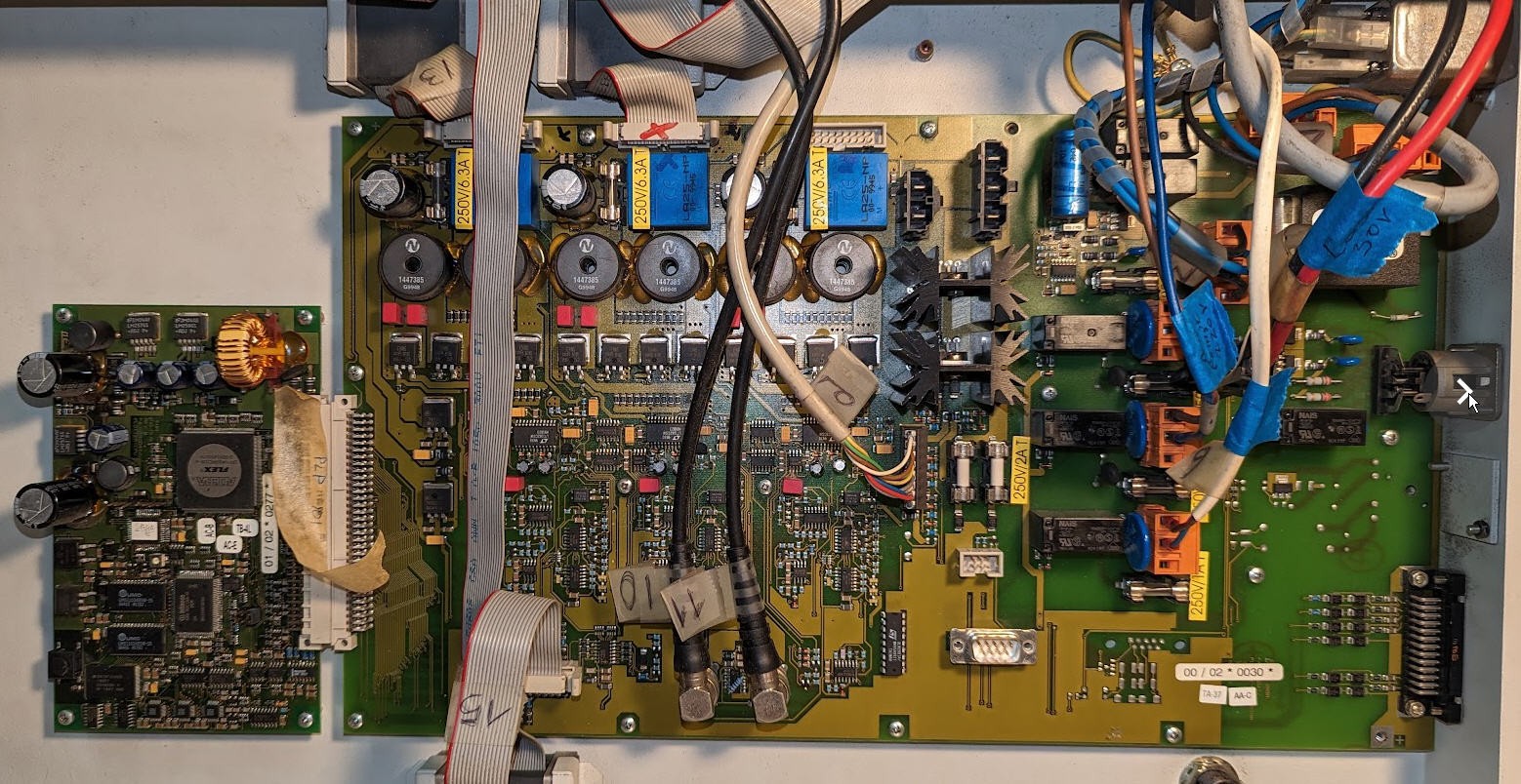
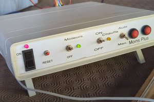
From all this I will only reuse the main switch and the 30V laser power supply!
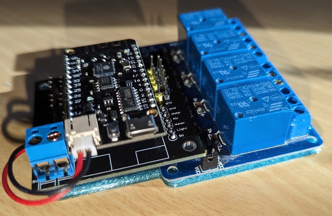
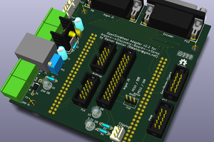
I have designed a new but simple control board. This control board will work with FluidNC firmware and can control most of "K40" like laser Power Supplies.
Details are provided into this log : FluidNC laser control board
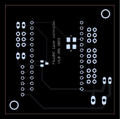
Once soldered the board remains very compact and can be fixed using this 3D printed support.
Laser tube
The old laser tube was very beautiful 2 laser beams collimated with polarizing mirror
(here in its "juice")
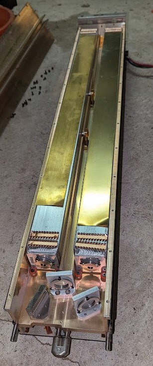
It was very sturdy and manufactured by Synrad. As I couldn't afford to replace it I chose a more classical CO2 30W tube (given by a colleague of mine).
The sticker doesn't give a lot of information excepted that a laser is a dangerous device. Which is totally right.
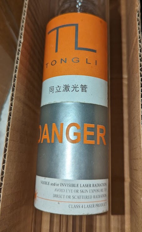
And it seems to be a 30W laser tube manufactured by Tongli in China:
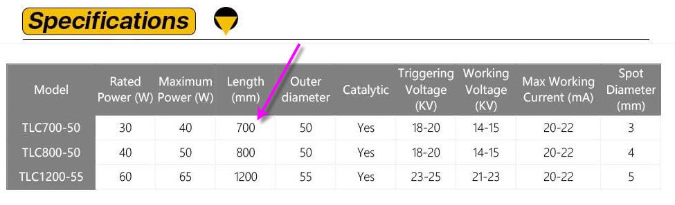
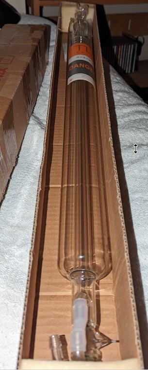
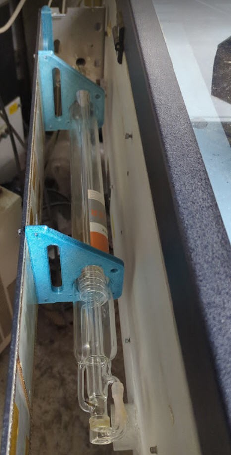
Being 70cm long this tube could be mounted quite easily on the body of my Trotec. Just a matter of printing a few brackets with my 3D printer.
Water Cooling
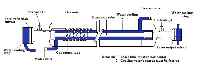
Water cooling the laser tube is critical to avoid damaging it.
Here are the recommendations that I followed:
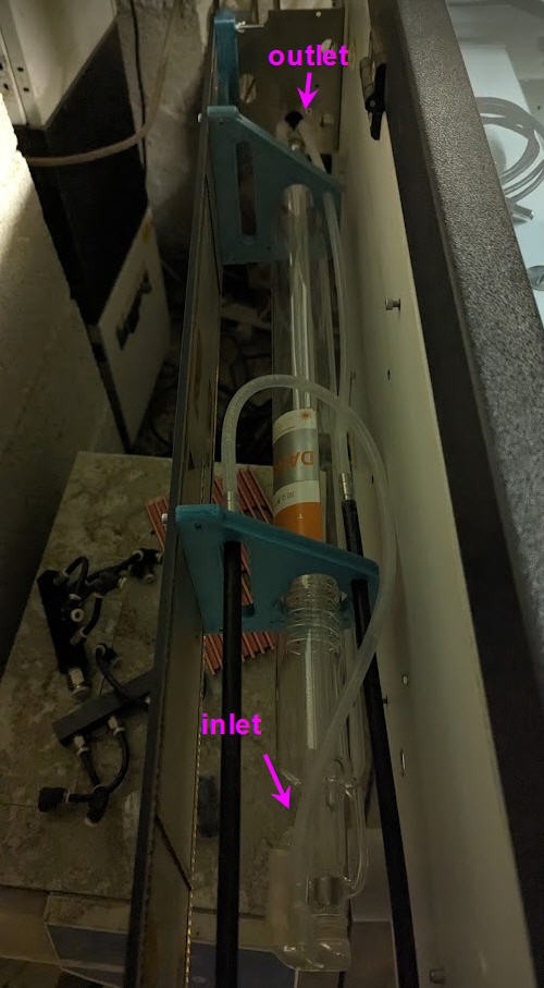
And the result where silicon tubes help to connect my chiller to the laser tube.
laser PSU
When I had been given this laser tube (yes it was a present! ) I also got a laser PSU. But all this without any documentation.
The PSU looks like this:
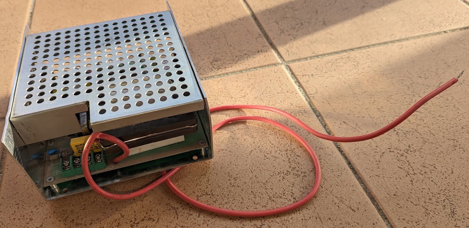
I soon discovered that the red wire was the high voltage, able to output up to 20000 V... CAN BE LETHAL.
On the other side is a serie of connectors:
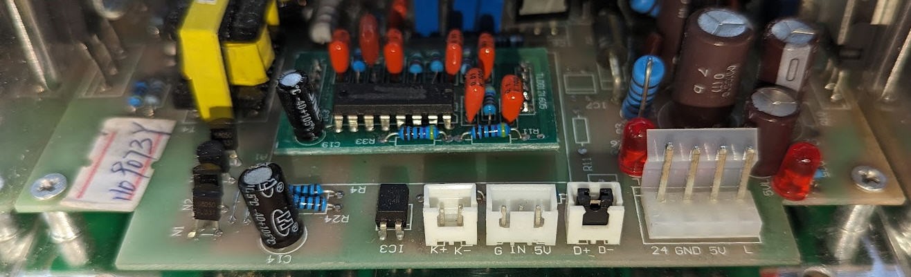
They are used to control the laser. But how ?
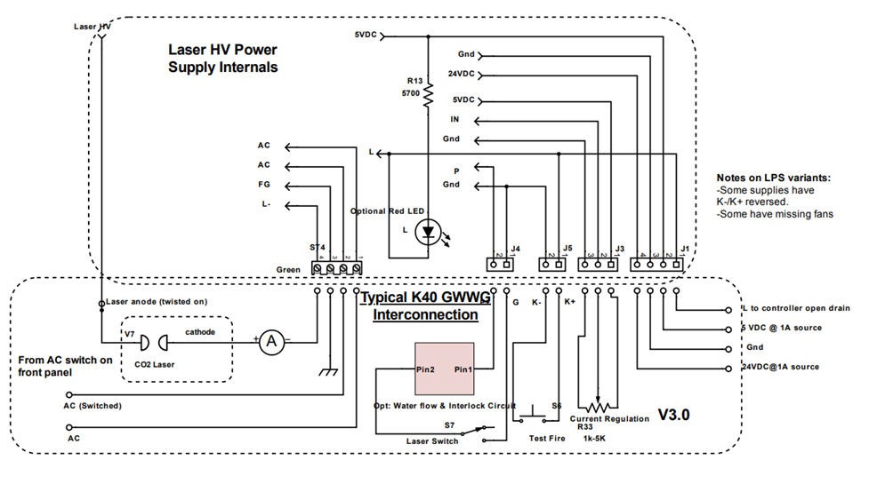
Searching on google I finally found Don's laser things blog which had a lot (I mean a lot!) of useful information about lasers PSU.
It took me a few hours to find that my PSU was quite similar to a K40 PSU but not exactly the same as this one.
So to be sure I reversed ingeneered the input stage of my PSU and found this schematics:
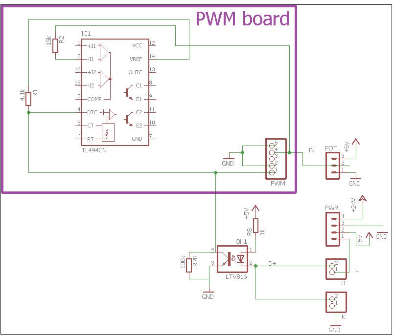
- K connector it thus the "laser trigger" switch. Short these pins and the laser will fire
- POT is a potentiometer to fix the laser power (max 20-22 mA)
- D connector is an interlock switch input (when shorted the laser L signal can also trigger the laser)
- L wire is the trigger pin of the laser (PWM coming from the controller board)
D, L and K all go to the led of an optocoupler (5V DC)
R1/R20 is a voltage divider between VREF (5V) and ground. This voltage divider is applied to pin DTC (dead Time Control) of the PWM chip
- when opto is off (L pin or K pin or D pin not grounded) then the phototransistor is not passing and the voltage divider is applying R20/(R1+R20)*5V = 4.8V to DTC pin
- When opto is grounded then its phototransistor is passing, pulling pin4 to (almost) ground. Thus the output of the voltage divider is now 0V (almost)
If we look at the datasheet we can read: 9.3.3...
Read more »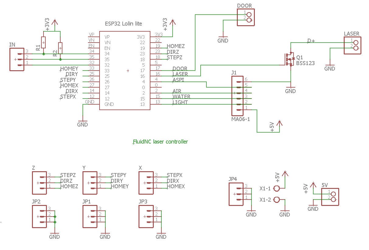
 iliasam
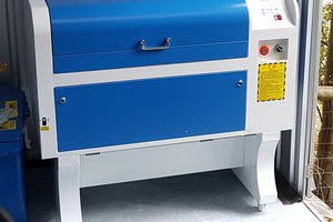
 Rainer