 JP Gleyzes
The idea
I have an old Trotec laser engraver. It was built in 1998 and worked quite well until this summer 2023. So I would say that it was a very reliable machine but it now suffers from its old age:
- laser tube is dead
- software is very very old fashioned and runs (tries to run) under windows 95 operating system
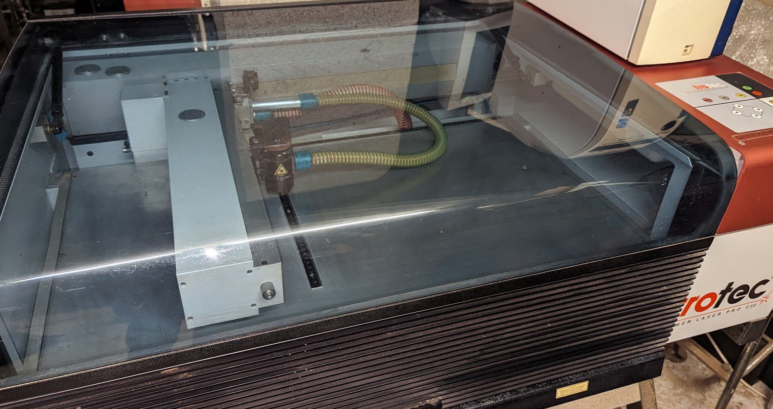
So it was time to trash this machine... But it looked so professionnal that I decided to refurbish it with more modern electronics.
- As I am an hobbyist I couldn't afford to buy a new RF laser tube, so I decided to change it to a cheap 40W CO2 tube
- As I love ESP32 and micro controllers I decided as well to design my own controller boards based on GRBL FluidNC software.
Follow this project to see how all this can work as expected !
The control board
I was tempted to reuse the original control board. But without any schematics and with the "windows95 concern" I didn't do it.
The main board is complex. We can isolate the 4 servo motors controllers on top, the power supplies (30V and 220V relays) on the right and the CPU on the small left board.
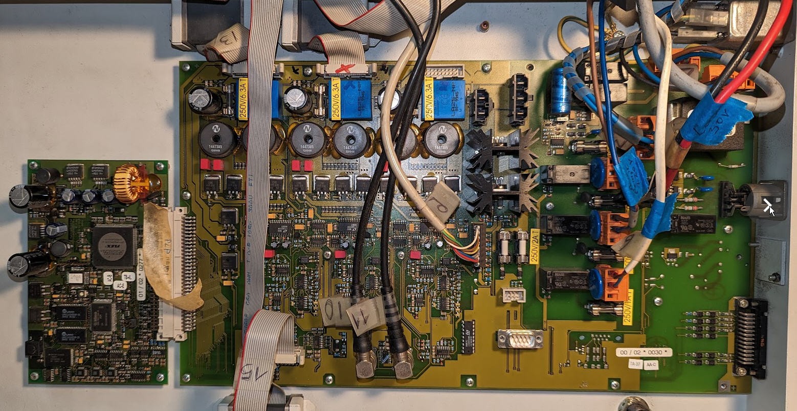
From all this I will only reuse the main switch and the 30V laser power supply!
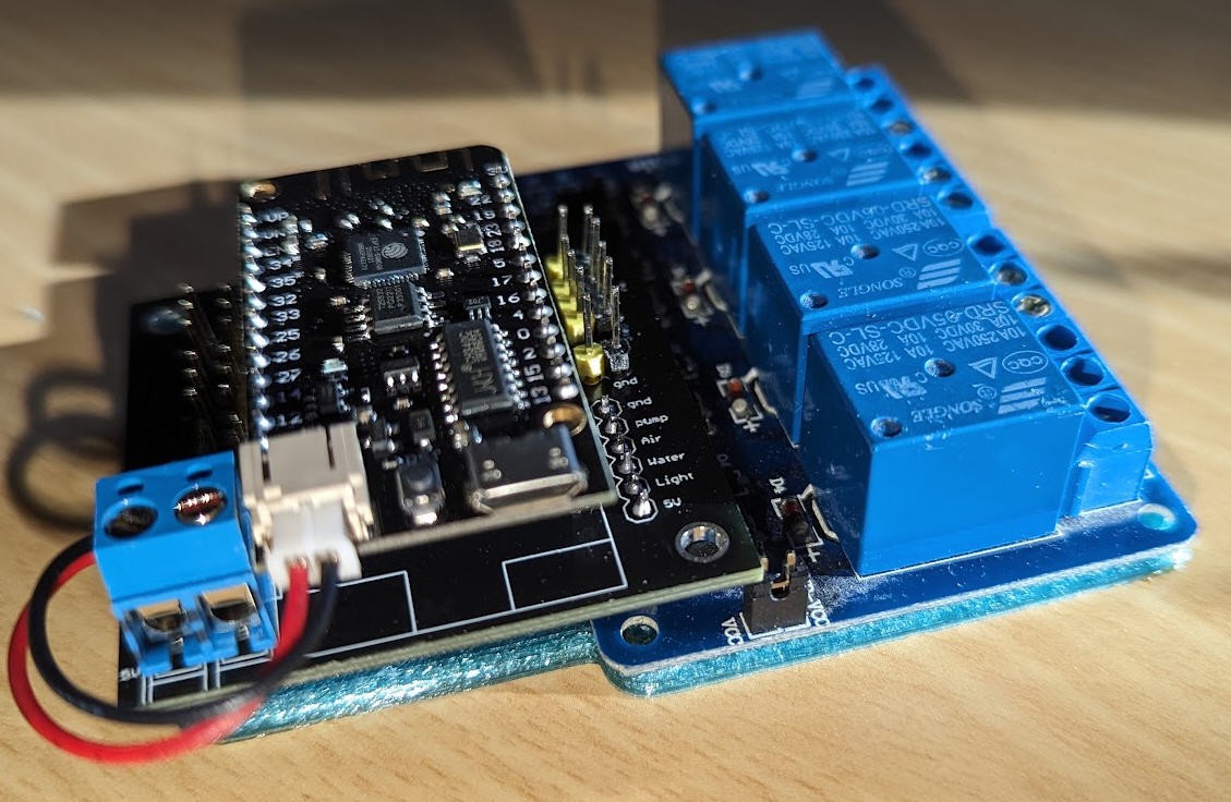
I have designed a new but simple control board. This control board will work with FluidNC firmware and can control most of "K40" like laser Power Supplies.
Details are provided into this log : FluidNC laser control board
Once soldered the board remains very compact and can be fixed using this 3D printed support.
Laser tube
The old laser tube was very beautiful 2 laser beams collimated with polarizing mirror
(here in its "juice")
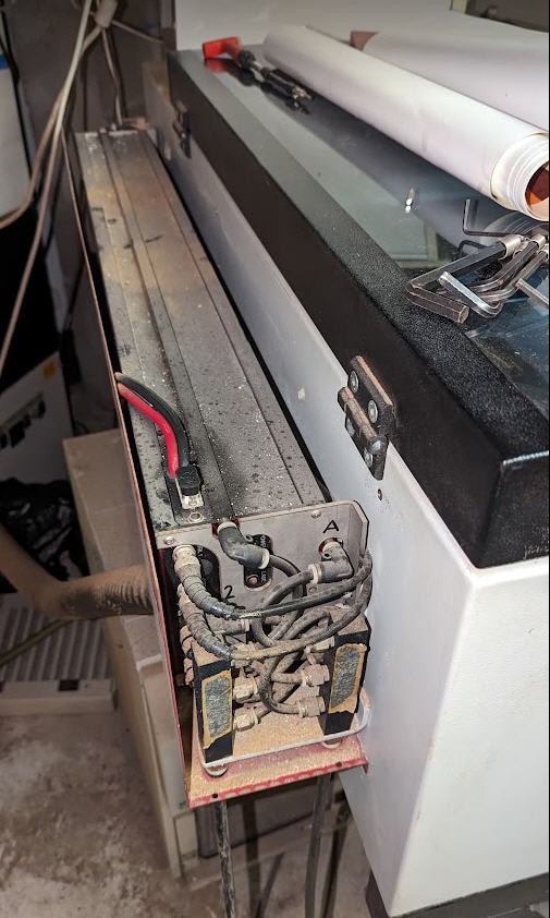
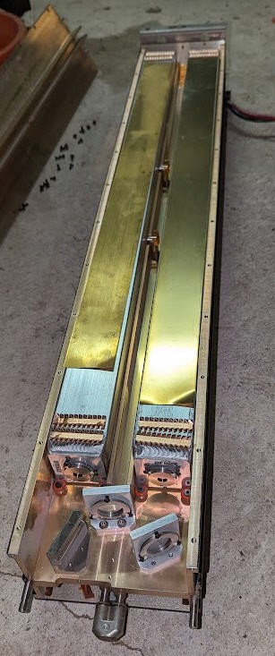
It was very sturdy and manufactured by Synrad. As I couldn't afford to replace it I chose a more classical CO2 30W tube (given by a colleague of mine).
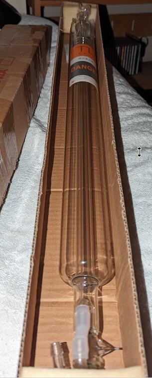
The sticker doesn't give a lot of information excepted that a laser is a dangerous device. Which is totally right.

And it seems to be a 30W laser tube manufactured by Tongli in China:
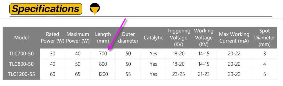
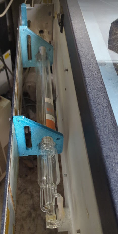
Being 70cm long this tube could be mounted quite easily on the body of my Trotec. Just a matter of printing a few brackets with my 3D printer.
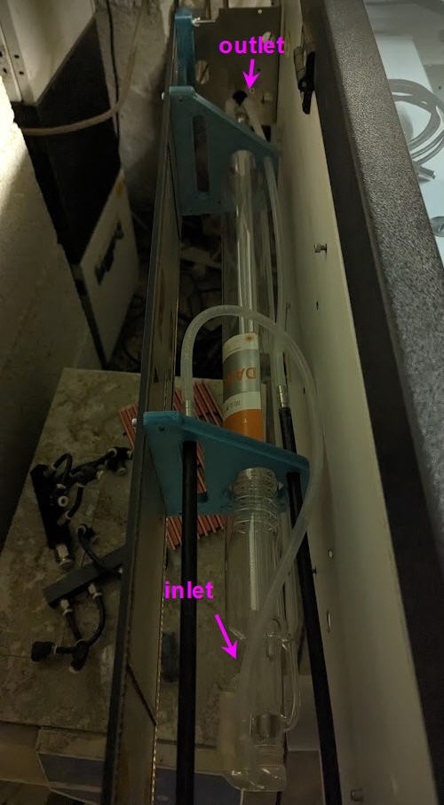
Water Cooling
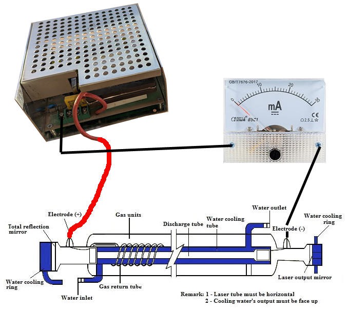
Water cooling the laser tube is critical to avoid damaging it.
Here are the recommendations that I followed:
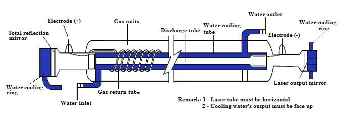
And the result where silicon tubes help to connect my chiller to the laser tube.
laser PSU
When I had been given this laser tube (yes it was a present! ) I also got a laser PSU. But all this without any documentation.
The PSU looks like this:
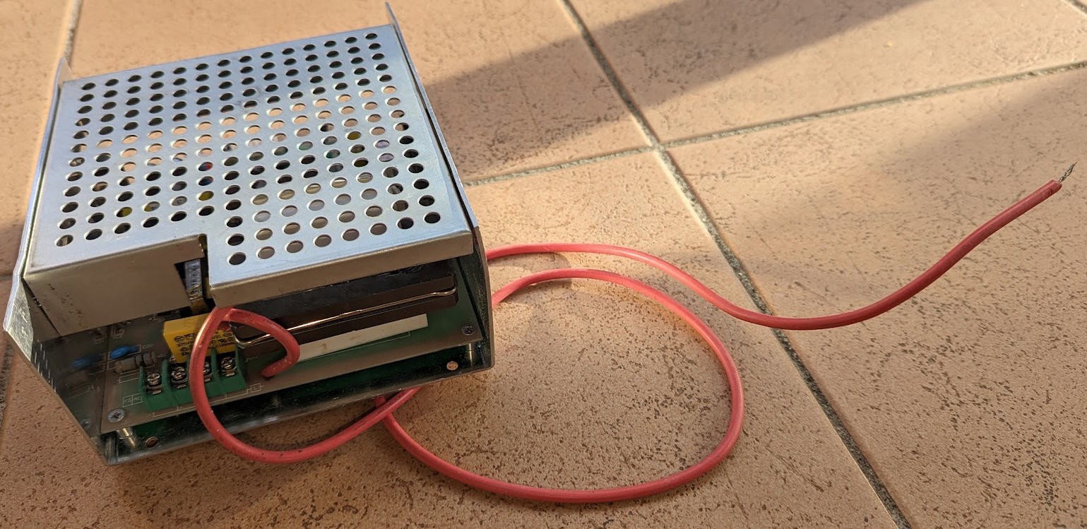
I soon discovered that the red wire was the high voltage, able to output up to 20000 V... CAN BE LETHAL.
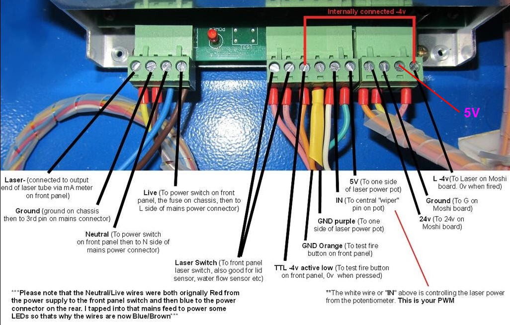
On the other side is a serie of connectors:
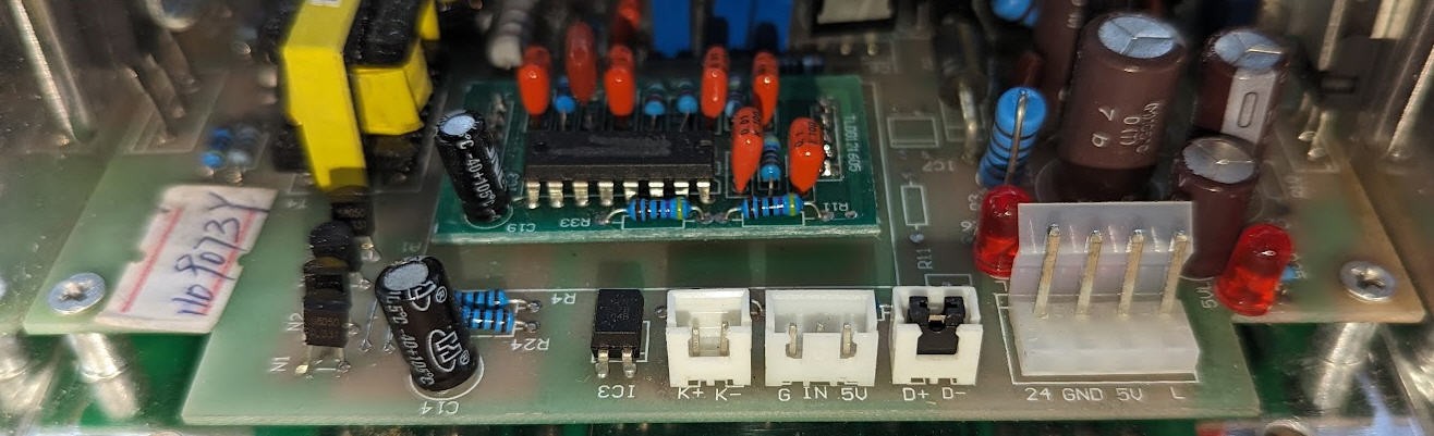
They are used to control the laser. But how ?
Searching on google I finally found Don's laser things blog which had a lot (I mean a lot!) of useful information about lasers PSU.
It took me a few hours to find that my PSU was quite similar to a K40 PSU but not exactly the same as this one.
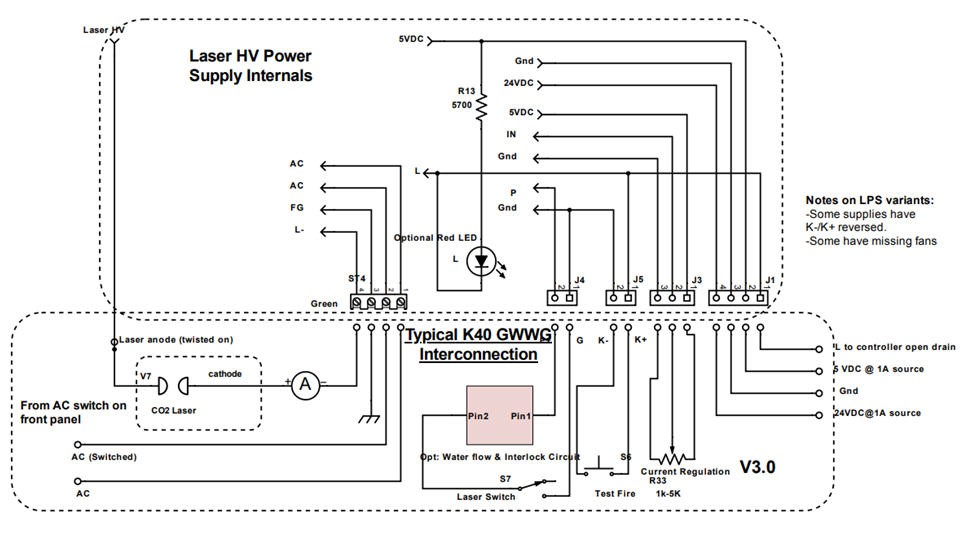
So to be sure I reversed ingeneered the input stage of my PSU and found this schematics:
- K connector it thus the "laser trigger" switch. Short these pins and the laser will fire
- POT is a potentiometer to fix the laser power (max 20-22 mA)
- D connector is an interlock switch input (when shorted the laser L signal can also trigger the laser)
- L wire is the trigger pin of the laser (PWM coming from the controller board)
D, L and K all go to the led of an optocoupler (5V DC)
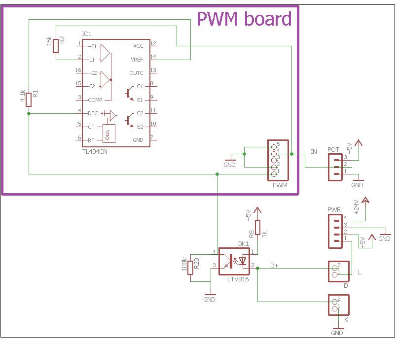
R1/R20 is a voltage divider between VREF (5V) and ground. This voltage divider is applied to pin DTC (dead Time Control) of the PWM chip
- when opto is off (L pin or K pin or D pin not grounded) then the phototransistor is not passing and the voltage divider is applying R20/(R1+R20)*5V = 4.8V to DTC pin
- When opto is grounded then its phototransistor is passing, pulling pin4 to (almost) ground. Thus the output of the voltage divider is now 0V (almost)
If we look at the datasheet we can read: 9.3.3 Dead-time Control The dead-time control input provides control of the minimum dead time (off time). The output of the comparator inhibits switching transistors Q1 and Q2 when the voltage at the input is greater than the ramp voltage of the oscillator. An internal offset of 110 mV ensures a minimum dead time of ∼3% with the dead-time control input grounded. Applying a voltage to the dead-time control input can impose additional dead time. This provides a linear control of the dead time from its minimum of 3% to 100% as the input voltage is varied from 0 V to 3.3 V, respectively. With full-range control, the output can be controlled from external sources without disrupting the error amplifiers. The dead-time control input is a relatively high-impedance input (II < 10 μA) and should be used where additional control of the output duty cycle is required. However, for proper control, the input must be terminated. An open circuit is an undefined condition.
So that, this DTC pin is indeed used to control the output of the PWM. When K or L or D is not grounded DTC pin is at 4.8V → full dead time… power off. When K or D or L are at 0V then DTC pin is at its lowest value (110mV) → minimal dead time. The laser is totally On. The LPS is regulated by the other comparators (IN input)
To summarize :
- A potentiometer (1k to 5k) can control the "intensity" of the laser (maximum power 20 to 22 mA)
- L should be fed by a PWM (5V) signal to modulate the output power
- D should be connected to interlock switches (or shorted if this interlock is not used at the PSU level)
- K is the "laser test" button
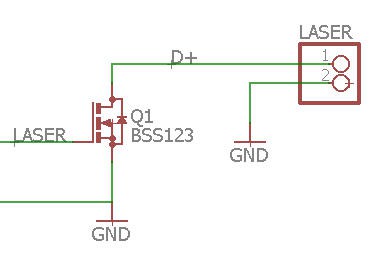
And this is what has been done on my controller board. The mosfet Q1 is there to adapt the 3.3V IO (LASER pin) to the "TTL" 5V level of the PSU.
You should also be aware that the 24V output of the PSU is quite weak (1A max) so it must not be used to power your motors... On the other hand, the 5V output can safely power the controller boards.
- All the power supplies must share the same ground.
- The high voltage wire (thick red wire) must be connected to the anode of the tube and properly insulated with silicon.
- The negative side (cathode) can be a "normal" wire and doesn't carry high voltage. HV drops down to almost 0V after laser discharge into the tube. The cathode should go to the ampere meter (+ terminal). The neg terminal of the amperemeter goes to the laser- (ground) of the laser PSU.
stepper motors
The most classical way to pilot a CNC machine is to use stepper motors. And this is the standard interface that FluidNC is using.
My Trotec laser engraver used servo motors... So it was incompatible with FluidNC and most of other CNC controller boards.
I thus decided to adapt my machine to act "as a stepper" that is to be controlled by Step and Dir signals.
This is fully explained into a specific project here : let's convert a DC motor into a stepper one
So now, my laser was moved by "pseudo steppers" as shown into this short video (jog mode with FluidNC and gsender)
Unfortunately I quite soon discovered that these "pseudo steppers" even if controlled like real steppers do not behave axactly as a stepper behaves.... Non linearities induced by the PID controllers do exist and prevent controlling the speed of motion. Which is critical for a CNC machine.
Here is the result of two "pseudo steppers" controlling X and Y axis of my machine. This is the pen plot of a straight line x=y into this cartesian plane.
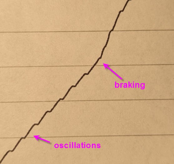
These non linearities are too much visible to be acceptable.
Consequently I will replace the servo motors of my Trotec by genuine stepper motors...
Wirings and integration
Relays
Initially I wanted to command :
- light (220V switch)
- air assist (220V switch)
- vacuum (TTL relay contact)
- water cooling (220V switch)
I finally thought that controlling the water cooling was not a good idea... I indeed prefered to have it run (same plug) as soon as the laser PSU is On without any chance to run the laser without cooling. So this relay on my board will be left unused !
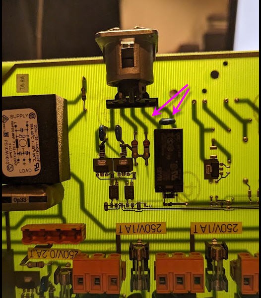
Regarding the vaccum cleaner, after looking at the Trotec control board, I found that shorting these pins (relay output) was starting the pump. These other pins should be used to control the extraction speed, but the potentiometer on the device is still working so manual control of the speed will be enough !
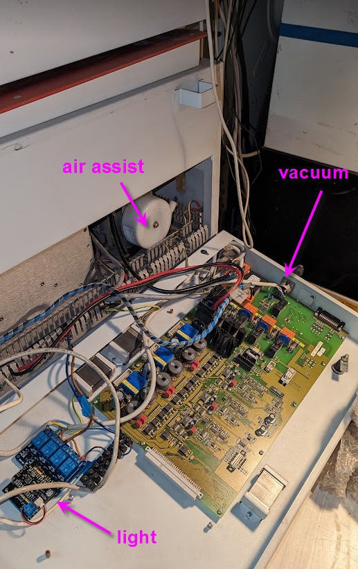
Here are the relays fully connected to the devices. We will see later how to configure FluidNC to recognize these relays !
As it is quite specific to my Trotec laser, I won't describe more this wiring.
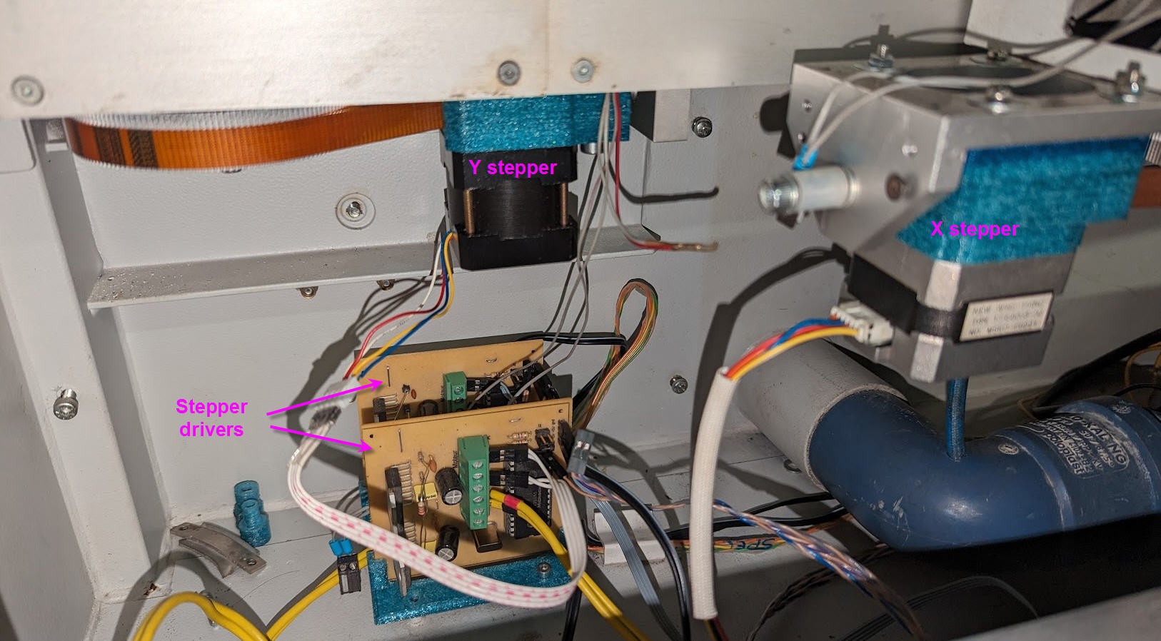
New stepper motors
I had two tiny NEMA17 stepper motors. After printing 3D parts to hold them in place, removing the GT1.5 pulleys from the servo motors and gluing them on the steppers shafts, here is my brand new Trotec now equiped with steppers.
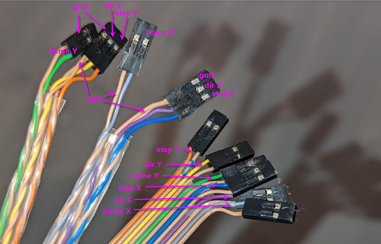
All this is connected with twisted pairs wires preventing parasitic behavior:
Very first test
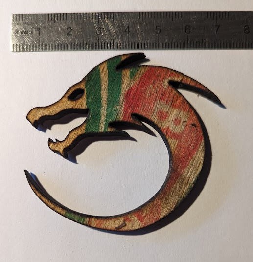
I mounted a pen on my laser head using the lens holder to keep it in place. It is a very flimsy mount but just strong enough (barely) to show the X and Y axes running together.
Here is the result. When printing the dragon head the pen got loose... But look at the rest of the drawing !
FluidNC configuration
We will only focus on FluidNC configuaration.
If you don't know how to install FluidNC, please refer to this log : https://hackaday.io/project/193659-lets-convert-a-dc-motor-into-a-stepper-one/log/225300-installing-fluidnc
Configuring FluidNC is not totally simple but if you follow the documentation it is feasible without too much difficulties.
Here is the config.yaml file for my machine.
name: FluidNC_trotec
start:
  must_home: false
  check_limits: true
axes:
  x:
    steps_per_mm: 77.16
    max_rate_mm_per_min: 4000
    acceleration_mm_per_sec2: 1000
    max_travel_mm: 500
    motor0:
      limit_all_pin: gpio.27:pu
      limit_neg_pin: NO_PIN
      limit_pos_pin: NO_PIN
      hard_limits: true
      pulloff_mm: 1.5
      standard_stepper:
        step_pin: gpio.12:pu
        direction_pin: gpio.14:low
        disable_pin: NO_PIN
    homing:
      cycle: 1
      positive_direction: false
      seek_mm_per_min: 1000
      feed_mm_per_min: 100
      mpos_mm: 0
  y:
    steps_per_mm: 77.16
    max_rate_mm_per_min: 4000
    acceleration_mm_per_sec2: 1000
    max_travel_mm: 500
    motor0:
      limit_all_pin: gpio.33:pu
      limit_neg_pin: NO_PIN
      limit_pos_pin: NO_PIN
      hard_limits: true
      pulloff_mm: 1.5
      standard_stepper:
        step_pin: gpio.26:pu
        direction_pin: gpio.25:pu:low
        disable_pin: NO_PIN
    homing:
      cycle: 1
      positive_direction: false
      seek_mm_per_min: 1000
      feed_mm_per_min: 100
      mpos_mm: 0
stepping:
  engine: RMT
  idle_ms: 250
  pulse_us: 4
  dir_delay_us: 0
  disable_delay_us: 0
Laser:
  output_pin: gpio.16:pd
  enable_pin: NO_PIN
  speed_map: ''
control:
  safety_door_pin: NO_PIN
  macro0_pin: NO_PIN
  macro1_pin: NO_PIN
  macro2_pin: NO_PIN
  macro3_pin: NO_PIN
  reset_pin: NO_PIN
  feed_hold_pin: NO_PIN
  cycle_start_pin: NO_PIN
  fault_pin: NO_PIN
  estop_pin: NO_PIN
user_outputs:
  digital0_pin: gpio.13:low
  digital1_pin: gpio.15:low
  digital2_pin: gpio.2:low
  digital3_pin: gpio.4:low
Reading this file is rather easy:
- at startup I do not require homing the machine but if I hit the limit switches an alarm occurs and motion stops.
- Then I describe two axis blocks which are identical (excepted pins numbers). Each axis is equiped with a single motor, which is a stepper.
- Homing of these axis can be done in the negative direction (going to the (0,0) coordinate in XY plane). Seeking this point will be done at 1000 mm/s then fine search will be performed again at slow speed 100 mm/s.
- Laser will be described later
- user outputs can control the 4 relays of my board.
First test of the laser
Well, to be clear it was a total failure... My laser PSU was dead... No voltage on the 5V nor the 24V...
I thus ordered a new one that I received 15 days later.
It's pretty much the same model but a little "newer".
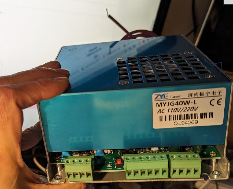
Connectors are more or less the same as previously:
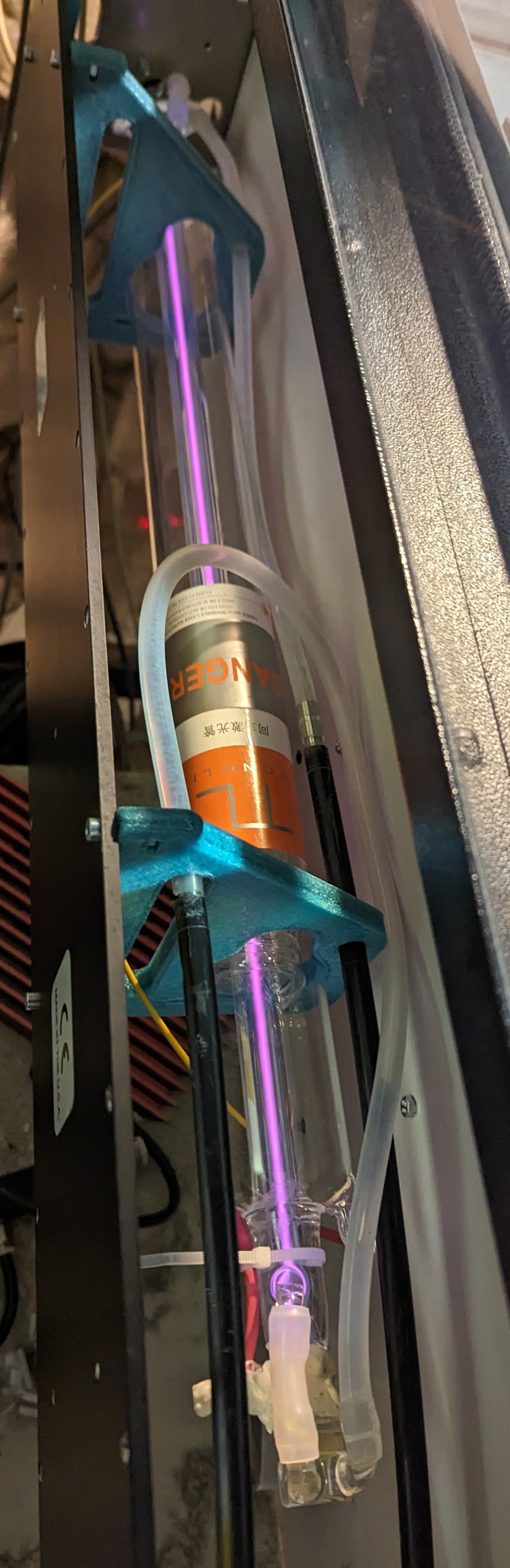
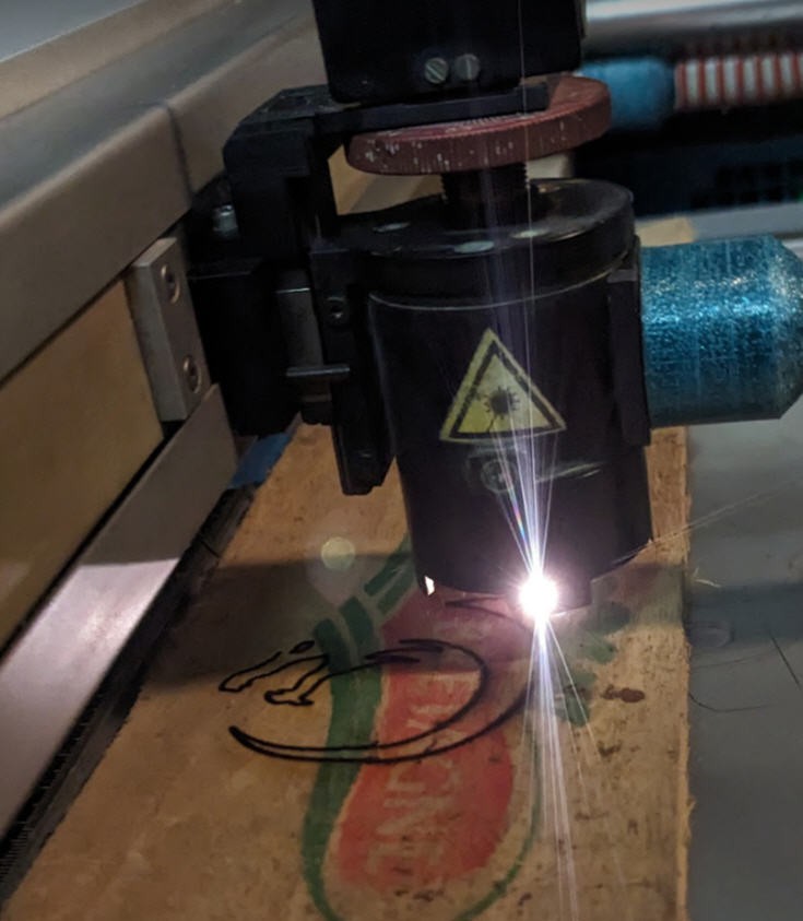
I connected all this and tried the "test fire" button. I must say that seeing this laser glow is really impressive (not to say freaking). But everything looks fine for now.
It is the very first test, sorry for the poor quality of the background of this picture, but my laser "lases"
First real cut
It was done after mirror alignment, I simply cut paper with 2000mm/min speed and laser at 6 mA.
Result is simply perfect. But I wanted to see how this small laser behaved with wood.
I took the first piece of wood I found: 5 mm thickness scrap !
And here is the result: speed 250 mm/min laser at 15 mA
It was almost cut with one pass... The second one was just there to "clean" remaining pieces of wood on the bottom side.
Air assist and vacuum cleaner were both On.