Martijn Schouten
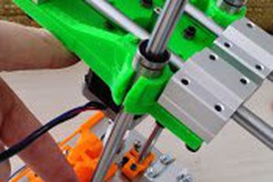
Multi-toolhead FDM is becoming more and more mainstream. First there was the E3D toolchanger and the Diabase H-series and recently Prusa has started shipping their Prusa XL. With the increase in increase in the number of toolheads, the complexity and functionality of the objects that can be printed is increasing. However, calibrating the tool offsets is also getting more and more complicated.
However, to calibrate XY offsets all manufacturers use calibration patterns (e.g. UltiMaker and Prusa). Calibration using these patterns is not very accurate and it also is very tedious. Therefore I have made an attempt to improve on this process and make it more accurate. At same time this process does require you to buy and install any hardware. Instead, it uses a commercial scanner that many people already have.
The idea of the process is that you print a calibration pattern on a piece of paper that you tape to your print bed. You then take this pattern and put it under a flatbed scanner. The scan is then analyzed using an image processing script and spits out the tool offsets.
To do this we need two pieces of software. The first piece is a Python gcode generator that produces the calibration pattern. The second is an image processing script in Matlab that analyses the scans. Both can be found in this git.
While most calibration patterns for manual calibration use a vernier pattern. This is pattern is nice because humans can easily determine the offset from it but for image analysis, this kind of pattern is not ideal. Instead, I use a pattern that looks like a vernier pattern but isn't. The pattern consists of two interlocked combs, like the vernier patterns. Also one side of these combs is printed using a reference nozzle and the other using the to be calibrated nozzle. However, the spacing between the combs is the same for both patterns, which is different as a vernier pattern, where one has a smaller spacing. The reason for using a similar spacing on both patterns is that in this way I can use the entire pattern to determine the offsets, instead of just the point where they line up. This will improve the accuracy and reduce the sensitivity to little print defects.
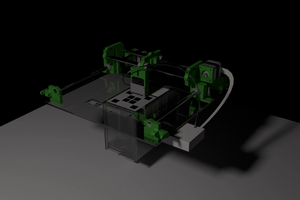
The pattern includes four patterns for each nozzle. Two for x and two for y. This is because the motion system of any printer will have a bit of play. This play will make that pattern will be on a slightly different position when drawn from the top to bottom as when drawn from bottom to top. The patterns are interlocked because this way if the paper is a little bit wrinkled it will have a very similar effect on both structures. The whole pattern is also printed under an angle this is because when printing on a standard bed slinger, this ensures that both belts are under tension all the time.

To determine the tool offset from these patterns the image processing script first detects the box around the pattern. It then determines the rotation of the structures fitting a line on one of the edges and determining the angle of that line. This angle is then used to rotate the scan of the calibration pattern such that is straight again (step 3). After the calibration pattern is straightened, all the lines of each individual calibration pattern are divided up into lines drawn by the reference nozzle and lines drawn by the nozzle that is being calibrated (step 5). In the next step, the image detection looks if the lines by the reference nozzle are exactly in the center of those drawn by the other nozzle or if they are slightly off. By also determining how far they are off from the center the script can determine the phase offset.
For those interested the way it looks if the lines are exactly in the center was quite a challenge. To do this, the script first converts the into a signal. This signal is low where there is a line and high where there is no line. The image processing script then uses an advanced signal processing step called quadrature phase detection...
Read more »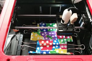
 Ahron Wayne
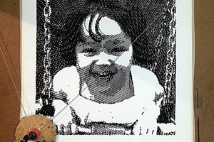
 ronald