 Andrew Kotite
Overview
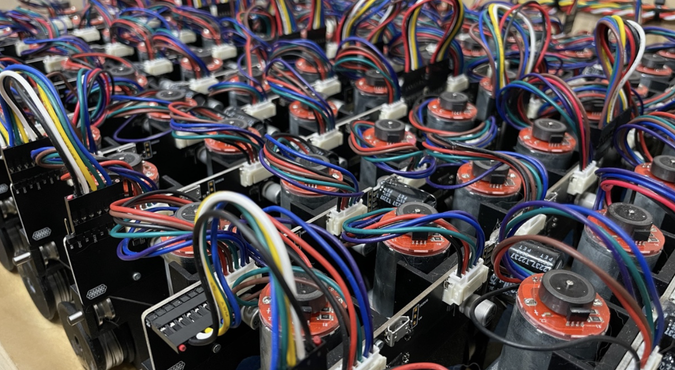
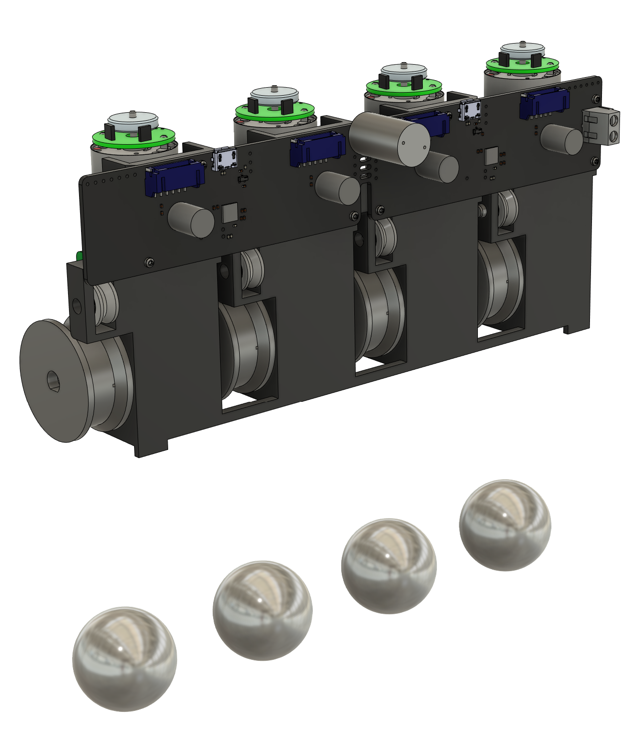
Internally, the sculpture is organized into modules of four motors. Every module has a circuit board with the motor drivers, power regulators, comms interfaces, and two microcontrollers. Each microcontroller is responsible for the position control of two motors.
The modules are chained together through 7-pin connectors that carry power and communications, zig-zagging back and forth to form the ten rows of the sculpture:
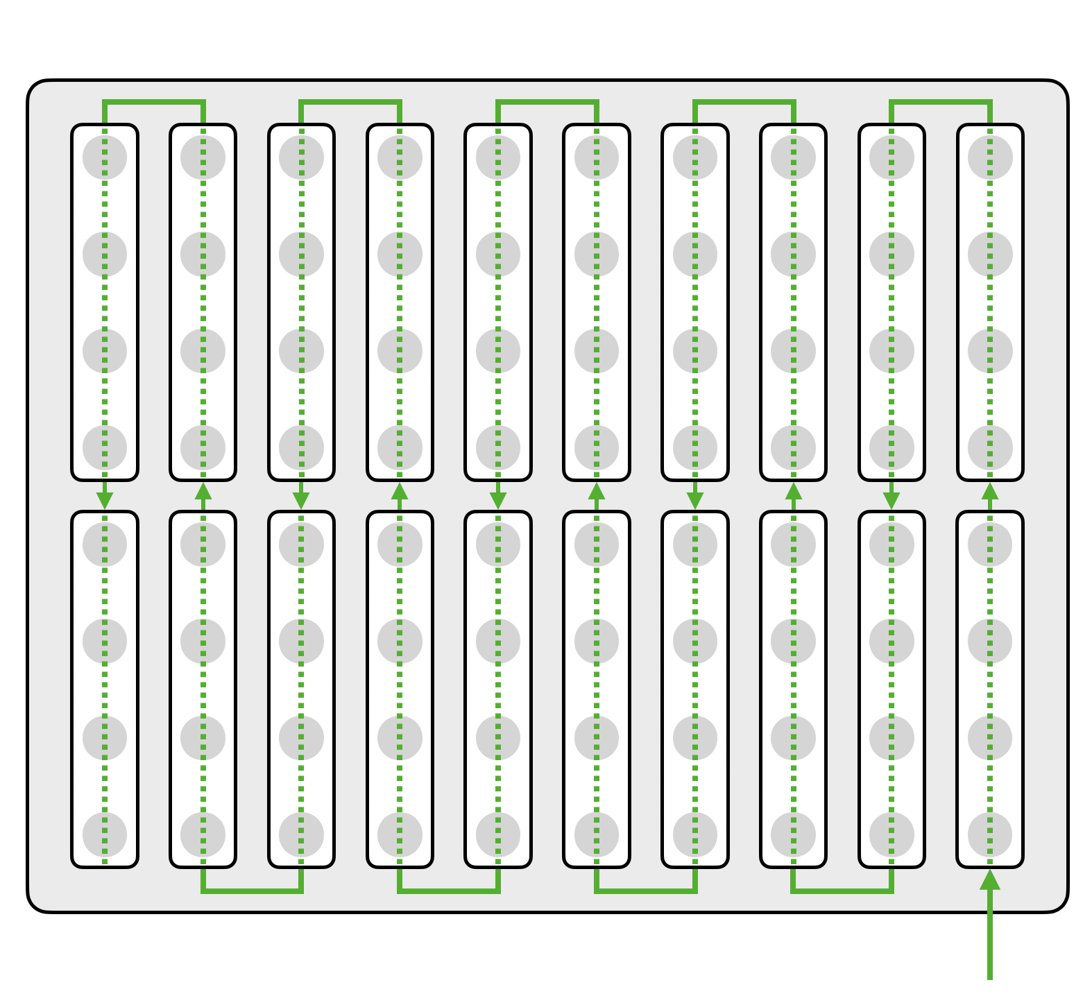
A Raspberry Pi connects to the first module in the chain (at the lower right corner, above) and handles the overall control and coordination of the sculpture, from animation to homing to firmware updates. It also drives the lights directly.
The modules are powered by five 6-volt power supplies (one per two rows), while the Raspberry Pi and lights are powered by a single 5-volt supply.
Mechanical
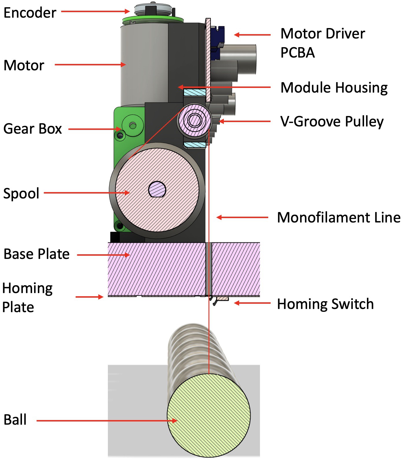
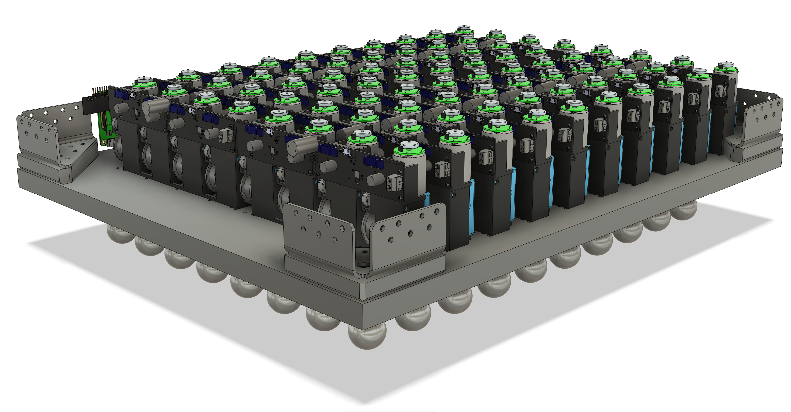 The module housing is designed to be 3D printed, and it provides mounting features for the motors, pulleys, and circuit board, as well as features to locate and mount the modules in the enclosure. In an effort to reduce part count and make assembly simpler, many components are held captive in the housing by other components. For instance, the pulley axle is held in place by the housings of the motor gearboxes on either side.
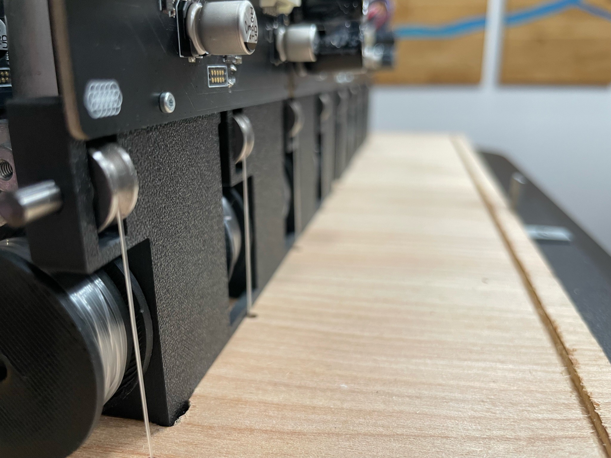
The cables that hold the balls are routed such that the weight of each ball provides a sideways load through the motor gearboxes into the housing, which eliminates the need for glue or retention screws to mount the motors. A light friction fit suffices to keep the modules in place.
Base Plate
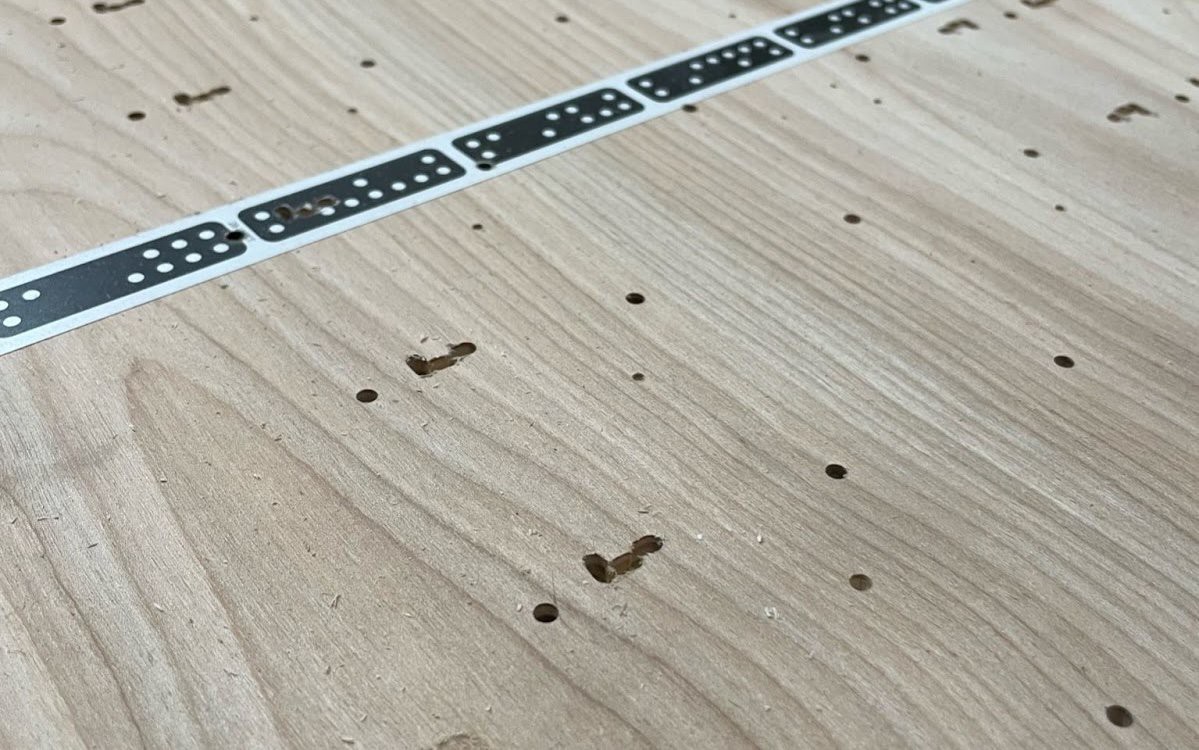
The placement of the modules relative to each other and to the rest of the enclosure relies on features CNC milled into the base plate (the bottom of the enclosure). We used a Shaper Origin to cut out alignment slots for the modules and drill holes for the ball cables to pass through (and later to cut channels used for the homing plate interconnect boards, more on those later).
![]() Motors
Motors
 Motors
There were many things to consider when selecting a motor: how fast we wanted the balls to move, the position resolution we could get, noise, power, and, of course, cost.
It quickly became clear that brushless and stepper motors would be prohibitively expensive for the first version of this project, so while there are drawbacks to DC motors, we ultimately found a supplier of semi-custom motors that we were happy with. They include a 48-count magnetic rotary encoder, a 143:1 gearbox with a worm gear, and a connector, all for $6 each. Having all that integrated into one unit also greatly simplified the mechanical design. The worm gear is important, as it prevents the balls from falling and crashing when power is lost.

Balls
Once we figured out the ball size and spacing, we started to think about how to attach a cable to a solid steel ball. All of the solutions we considered involved drilling a hole into the balls, which would be a big challenge without specialized equipment. Luckily, we were able to find a supplier that could machine the balls for us, drilling and tapping a 10mm M3-threaded hole in each one. To attach a cable to a ball, it's passed through a vented set screw and knotted off, then the set screw is screwed into the threaded hole.
Homing Plates
The encoders on the motors give us great incremental position sensing, but we needed a way to accurately zero the balls to a known reference point. To do this, we made four homing plates, which are circuit boards with micro switches above each ball. During the homing process, a ball gets its zero position from hitting its switch. We also took the opportunity to add 172 addressable RGB LEDs to these boards to give the sculpture its own lighting.
In the photo below, you can see the homing plates, LEDs, switches, and the 3D printed ball guides around each hole. These guides protect the switches from strain, and they stop any side-to-side movement of the ball if it's swinging as it comes up to the switch.
... Read more »


Insightful write-up with information I feel could be applied to my own projects in the future.
Was there any particular reason why UART was used over other protocols?
What do you think it would take to design modules that were modular and could be reconfigured similar to Neoleaf's or the Dumang DK6 keyboard?