 Sillhouette
-Hardware-
1. One thing that is really confusion is that the polarity of two magnet is negative (As shown on the figure)

Inside the ring magnet, the equal magnetic field is actually the negative. In this way, the float can float.
(To understand this thing spent me a plenty of time)
Meanwhile, the two repel magnet is not stable, as long as the force and gravity don't act on the same line, it can not maintain stable, and, it will be pushed out.
The method we use is to control the float by adding coil inside the under magnet. If only the float can't move to other horizontally direction, the gravity will be offseted by the magnetic force. In this way, the system can be maintained in a stable position.
To adjust the magnetude of the force, we use some sets of small magnet instead of a big ring magnet. The sensors we use is the hall sensor, the principle of it is that if the float is on the plumb line, the hall has no output since the the field line is vertical. But, if the float has a tiny bit tendency to offset the original position, the whole field line will change, thus, the hall can detect it and use the coils to pull it back.
2. Hardware
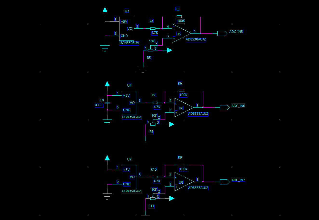
The UGN3503 was chosed as the hall sensor, the origin signal will be ampilfied by an op amp. One POT was added to adjust the zero voltage. After the installation is over, adjust the R5, R6 and R11, to make U5, U6 and U8 output 1.65V on the circumstance which the float weren't placed.
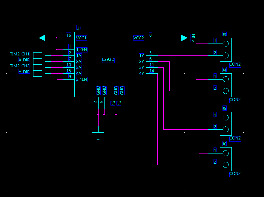
To drive the magnetic coils, a L293D chip is used. The L293D itself will be drived by the STM32 outputing PWM wave.
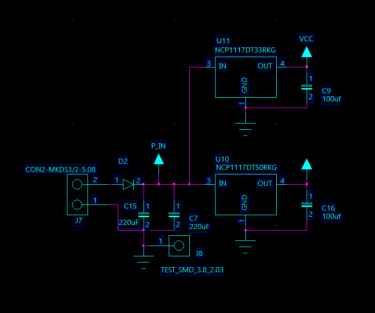
The whole system need 12V DC power supply at designing, but the L293D can't afford it, we eventually use 8V as supply. U10 and U11 give 5V to hall and 3.3V to control components.
A serial port is added to monitor the position of float, to make the following step easier.
J3 with J4 is a set while J5 with J6 is another set. The first set is to control X and J5 with J6 to control the Y position. The other thing is that the negative magnet need to installed in a same group, to ensure the field line are connected, incase to make the force act on the float are the same.
-Software-
1, The config of ADC
The voltage of ADC 5 and 6 reflects the x, y position of the float. The ADC 7, is used to detect whether the float is on, if the float doesn't exist, we will turn off the PWM output.
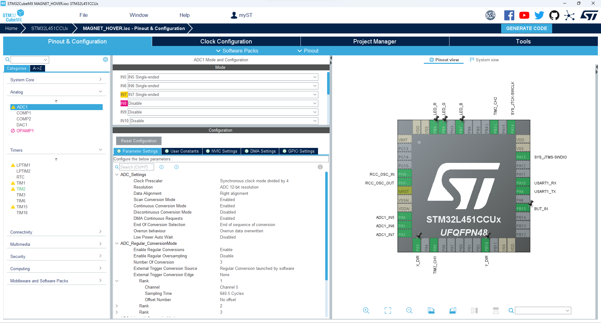
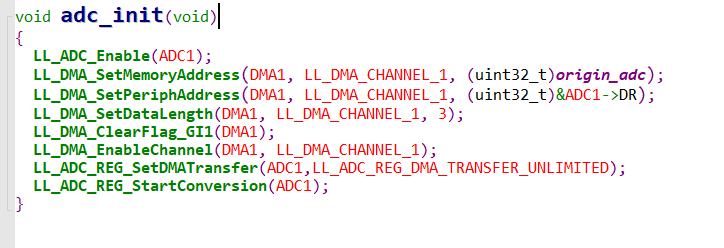
The main program is to initialize the ADC to work as the DMA mode, the ADC will convert contiunously. In the system ticks interrupt, we can get the position of the float, then use PID control loop to control PWM, which will actually affect the position of the float.
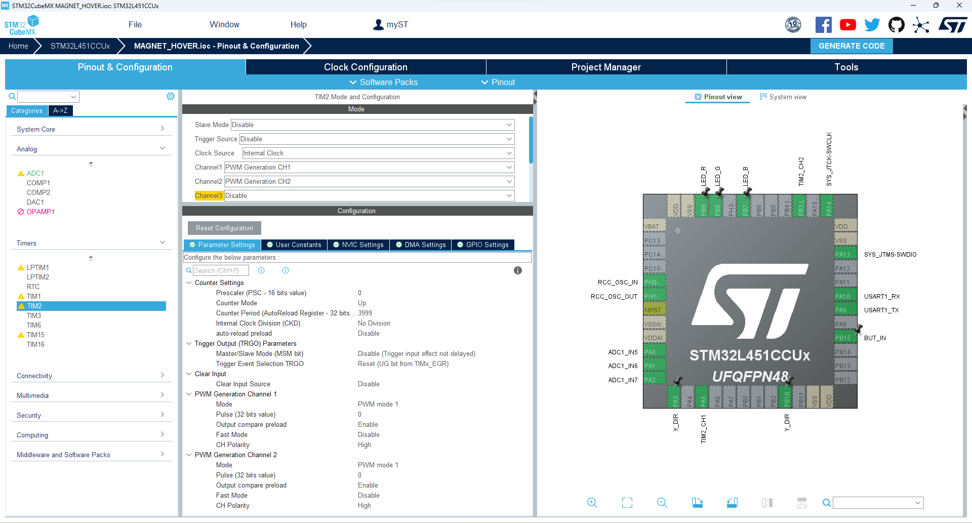
The PWM frequency is 20kHz, since the main frequency is 80MHz, so the counter period is 3999(4000-1)
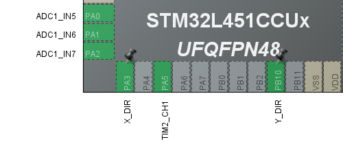
The PA3 and PB10 are the x and y current dirction output.
After that, the config of hardware is over. Use it to generate the IAR project and to write the code.
In the IAR project, Use below functions to initialize ADC.
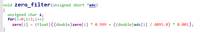
After power up, use first-order inertial filtering to clac the mid-point voltage, in our algorithm, the position of float is a float number of 0 to 1.
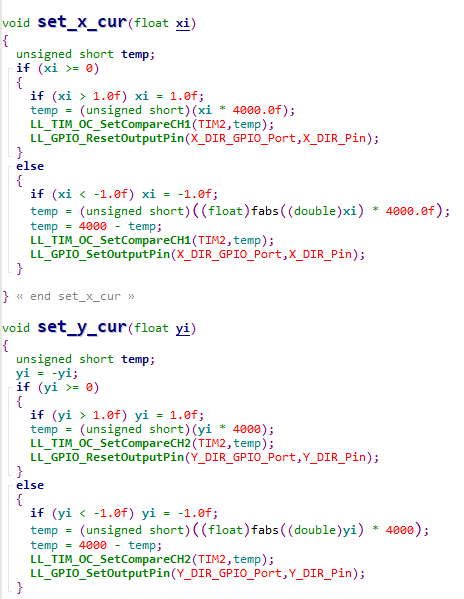
The upper functions is to set the pwm output on x and y positions.
The content below is the core of the whole algorithm.
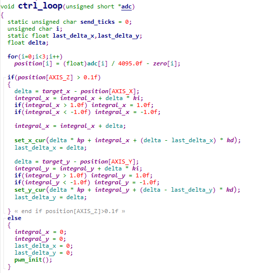
When position[AXIS_Z] > 0.1f is false, it means the float doesn't exist. So the program will reset the integral of x and y, and turn off the PWM output.
When is ture, the PId will be excuted, for instance, in the x axis, delta is the deviation of float. The integral_x is the output of integration. It will be saturated to -1 to 1. The delta - last_delta_x is the differentiation of the error, since the float nearly have no friction, so in fact, it doesn't have static error, so the ki = 0. Which the acutal control structure is PD.

 Benjamin Prescher
 Adam Taylor
 Mateo Estigarribia
 Juan-Antonio Søren E.P.