 Adam Taylor
Introduction
Robotics are at the forefront of the Industry 4.0 and edge revolution along with artificial intelligence and machine learning.
As such I thought it would be fun to create a base robot arm project we can come back to and add in several features such as:
- Inverse kinematics - determine the position of the end-effector.
- AI / ML - object classification during operation.
- Networked control - enabling remote control at the edge.
This example will use a robot arm which uses six servos under the control of a Zynq SoC. It will be controllable using either a simple software interface or using two Pmod joysticks to enable direct control.
Servo Control
The first thing we need to do is work out how we are going to control the Servo Position. Servos are one of the simplest motors to drive, and idea for robotics as they also hold position provided we maintain the same drive signal.
So what is the drive signal for a servo? Most Servos in the class we are using, use a 60Hz PWM waveform. In the 16.66 ms period of the 60Hz waveform, the signal will be high between 0.5 ms and 2, 5 ms. The duration of the signal will drive the servo in a range of motion between 0 and 180 degrees.
Driving a 0.5 ms pulse drives the 0 degree position while 2.5 ms will result in the 180 degrees. 90 Degrees therefore is maintained by driving the signal high for 1.5 ms.
Therefore increasing of decreasing the pulse width by 13.9 us moves the servo by 1 degree.
While we have the triple timer counters which are capable of providing the PWM signals necessary. We would also need to supply servo power at 6 volts in this application, therefore the simplest manner to make use of the Adafruit PWM Shield. This not only provides 6v power but also performs the level conversion on the PWM signal.
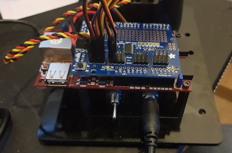
Ada Fruits Shield
The next thing to work out is how to drive the signals, the PWM shield uses four 8-bit registers to drive each PWM signal.
The device on the shield the PCA9685 uses a 4096 bit counter. The on registers define the count at which the signal goes high and the off the count at which the signal goes low.
As such we can always set the on time to 0 and then define the count at which we turn the signal off, to give us the width of signal required.
Vivado Build
To be able to interface with the Pmod Joysticks and the PWM shield we need to first create a design in Vivado. This design will contain the following IP blocks
- Zynq PS - This is the Zynq Processing System
- Pmod Joystick 2 - Interface to the Pmod
- AXI IIC - I2C interface implemented in the PL
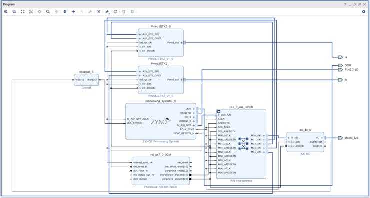
Vivado Design
To use the Pmod IP cores we need to have the Digilent Vivado library mapped in as a IP repository. If you do not have it you can obtain the repository here, you also need the Cora board definition installed, if you are missing these you can download them here.
Once we have the block diagram complete we can build the design and export it to software.
Software Design
It is in the software that we are going to be developing most of the application. As we want to use this in several modes and come back to it in the future for upgrades we need a modular approach.
As such I developed a function for each joint which can be called and used as desired. Each joint is capable of taking in a unsigned 8 bit value, this 8 bit value is then either added or subtracted from a the 90 degree (1.5 ms) pulse width to obtain the angle desired.
I did this for several reasons:
- A single RS232 byte can contain the desired motor position.
- Values read in from the joysticks are also 8 bits.
How we use the joysticks is interesting they give direct control over the arm. As such we need to ensure the movement between the joystick and arm aligns.
Of the two joysticks the first one is connected to JA and the second the JB.
JA when moved in the X direction will move the arm forwards or backwards, when moved in the Y direction it will move the arm up and down.
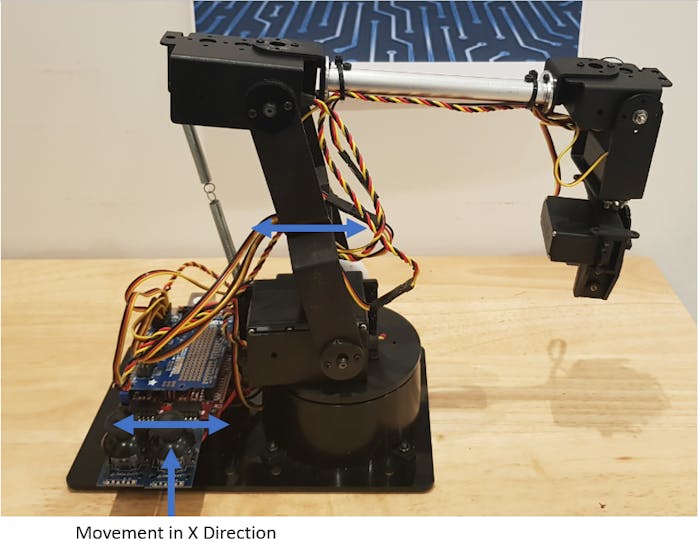
Moving JA in the X Direction...
Read more »
 Daphne
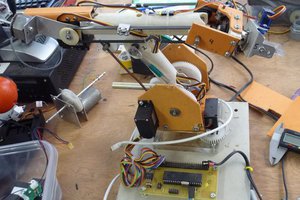
 Rue Mohr
 Aaed Musa