 The Lab Guy
Adding project details, etc. over time as I reverse engineer my own project!
Here are some specs of this machine:
- Customized Desktop / Workspace environment to honour the Z88 UI
- Built-in Application Suite to provide modern alternatives to the Z88 built-in apps
- Powered by Raspberry Pi 4 running Raspberry Pi OS
- Built-in 1920 x 480TFT screen, with custom capacitive-touch overlay
- Built-in mini physical keyboard with USB controller
- RAM as per RPi4 specs
- SD Card storage as per RPi4 specs
- WiFi as per RPi4 specs
- Bluetooth as per RPi4 specs
- Li-ion battery with battery management
- USB-C charging
- Wireless charging
- Hardware button to Power ON/OFF
- Hardware button to switch between Low-power usage and Full-power mode
- Tough ABS portable tablet style case
- Wireless charging base with ergonomic slope for easy desktop or laptop use
- Built-in Z88 Emulator (OZvm) with customisations to support hardware for those who want the "Real Experience" ;^)
And, of course, plenty of scope for expansion thanks to the Raspberry Pi 4's remaining unused I/O.
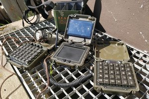
Photos of the internals of the Z88 Tribute
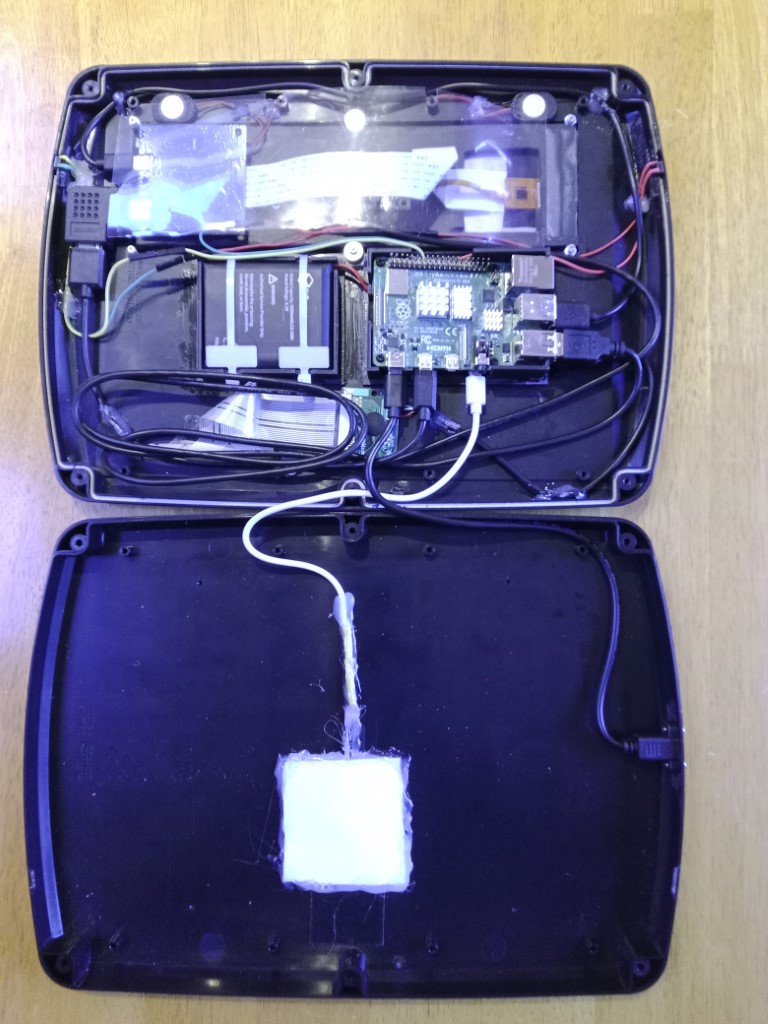
1. Open case. Screen and keyboard (face down) at the top of the photo. Wireless charger and USB-C connector at the bottom.
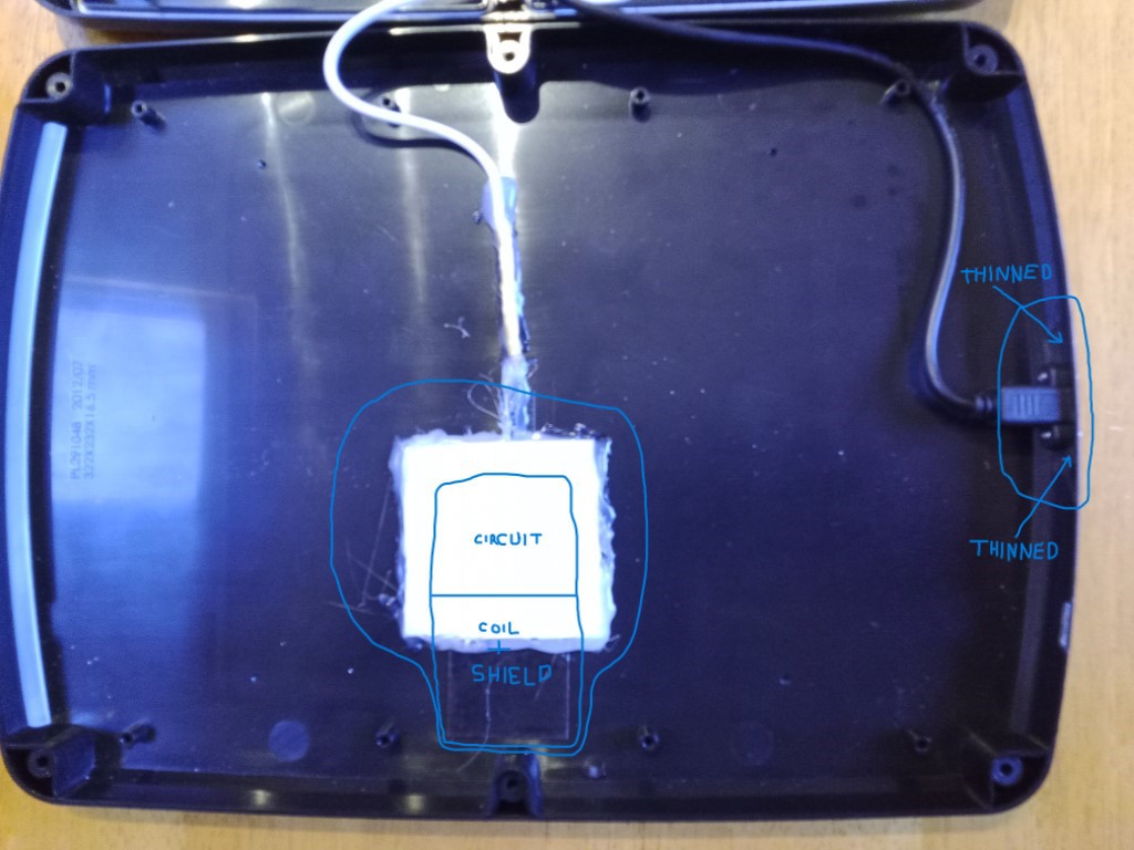
2. Closer look at the bottom of the case.
In the centre is the wireless charging circuit, which consists of a coil, a controller on a circuit board and an inductive shield in the form of metallised sticky tape. The coil is mounted so that it close to the top of the Z88 Tribute to allow it to be placed on standard commercially available wireless chargers, as well as it's own charger.
To the right of the photo the USB-C socket can be seen. The case wall has to be carefully scraped away until it is thin enough for a USB-C plug to make full contact inside the socket, when mounted and plugged into from the outside.
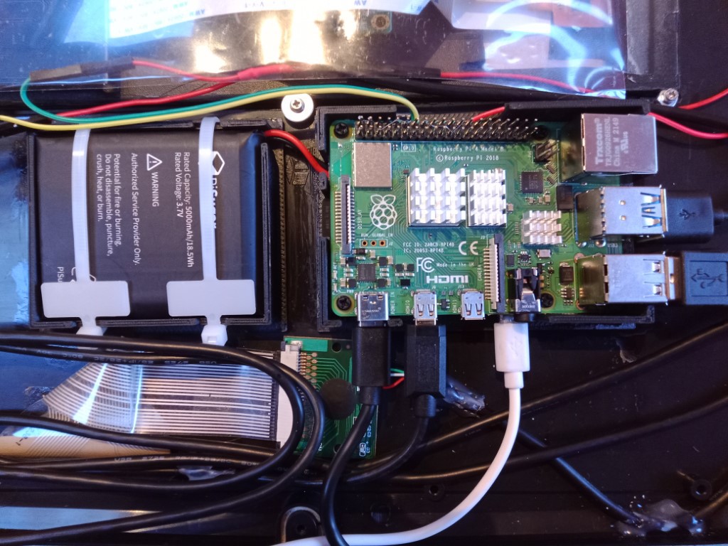
3. A closer look at the gubbins.
Below we can see the Raspberry Pi 4 on the centre right. Directly behind the RPi4 is a battery management circuit. Both are held in place by a 3D printed holder.
On the centre left is the Li-Ion rechargeable battery, also held in place by a 3D printed holder, plus a couple of cable ties.
Immediately below the RPi4 and battery is the keyboard matrix decoder for the built-in keyboard.
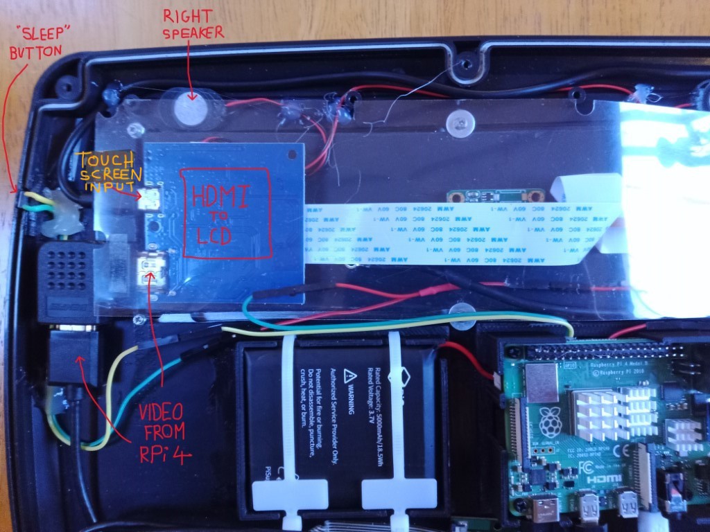
4. Audio and video close-up.
The HDMI to LCD board (which comes with the 1920x480 LCD screen) is removed from it's housing and rotated to the position shown in the photo, to allow connection to the HDMI output from the RPI4. This decision was forced due to the choice of connectors available.
The HDMI to LCD board also supports Multi-Touch Input via a micro-USB connector. Unfortunately, the display unit does not come with a Capacitive Touch Screen Digitizer, so a compatible one was sourced.
Notice above the HDMI board, one of the built-in loudspeakers and to the far left the "SLEEP" button. It's not a true SLEEP button, because the RPi boards do not support low-power sleep modes. Instead, I have configured it to shutdown the display and as many peripherals as possible.
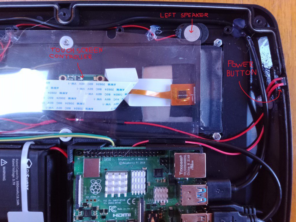
5. Audio and Touch-Screen.
Finally, towards the centre of the photo we can just see the Touch Screen Digitizer board, hidden beneath the flat white cable.
At the top, there is the other loudspeaker and to the far right, the POWER button. The POWER button triggers a clean shutdown of the OS and then the RPi4 itself.
 Nicholas Hill
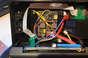
 MakeNModify
 Stephen M