 ElectroBoy
It’s been very long, I am making circuits on PCB and breadboard. But while testing the circuits on breadboard the main problem is to make the connections and supply it with a logic power. Digital circuits can be easily made but on the other hand breadboard connections may introduce some noise and clock errors if connections are large and not proper.
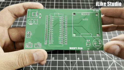
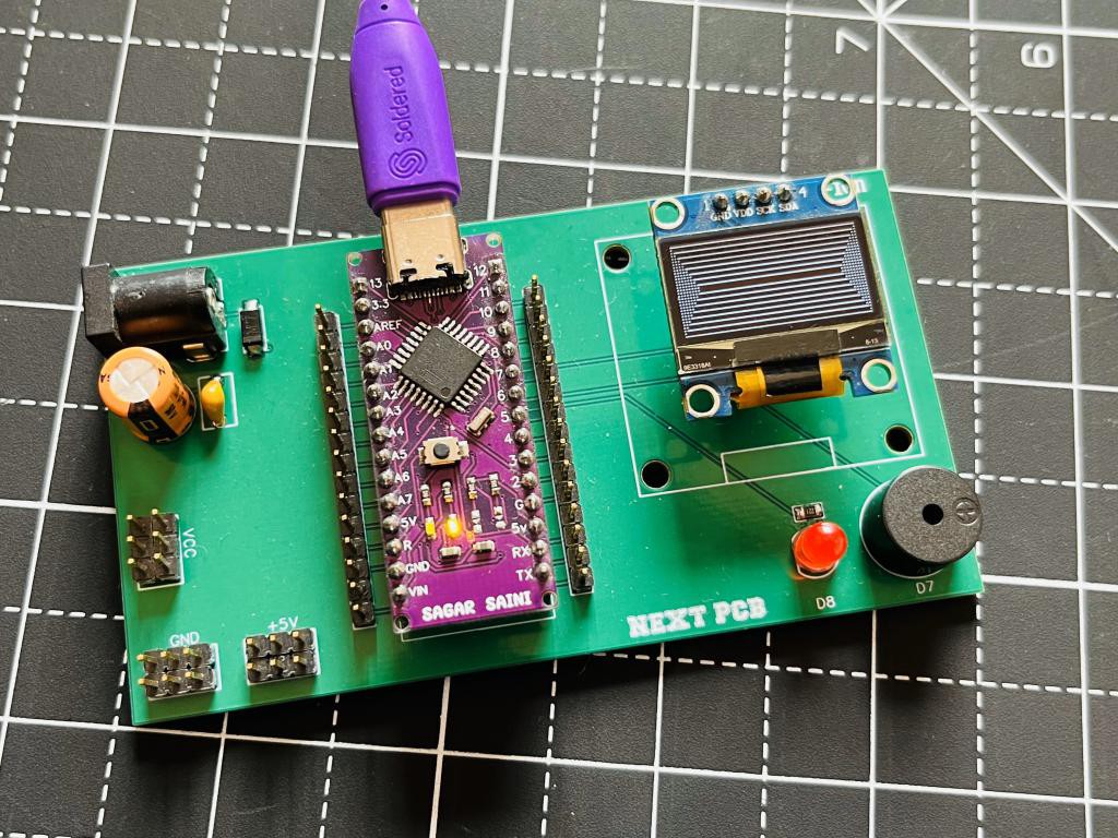
To solve this problem, I made a universal circuit by combining some peripherals, a microcontroller and power supply section. Now with this board we can easily test our circuits on breadboard and the connections like led indicator, buzzer, LED and microcontroller on this PCB will help to reduce the overall wires. NextPcb offer their services in PCB, PCBA, SMT assembly, Stencil, Component sourcing and BOM preparation. Order high-quality, reliable PCB starting at $1.9, multilayer starting at $6. Enjoy free PCB assembly for 5 boards.
Microcontroller:
The choice of microcontroller is very obvious because I want to keep it simple so that no external programmer is required in programming. I choose Arduino Nano, having a small form factor and a lot of I/O pins and it is very easy to program because of dedicated Arduino IDE.
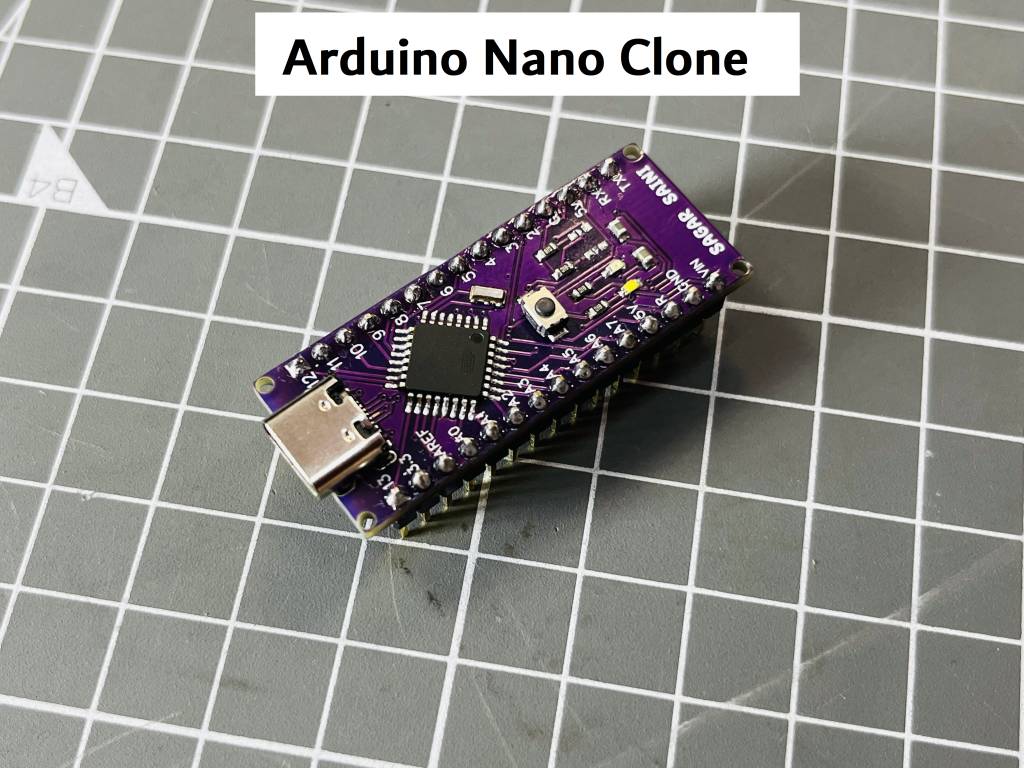
This Arduino is a clone version of the original that I made in my lab. Most of the clone boards have problems in uploading code so I choose to make my own with a dedicated programming chip (USB to TTL on back) and this one has type C USB. Here are the build instructions and link to the tutorial.
Circuit Diagram:
The circuit is very simple because we are using an OLED so I2C port of Arduino is required for this purpose, I2C is an interfacing protocol with support of 127 I2C devices, Address of devices should not be the same. Then two digital pins are reserved for on board Led D8 and buzzer D7. Power supply section has a 12v barrel jack, filtering capacitors and a diode to save the circuit from reverse voltage.
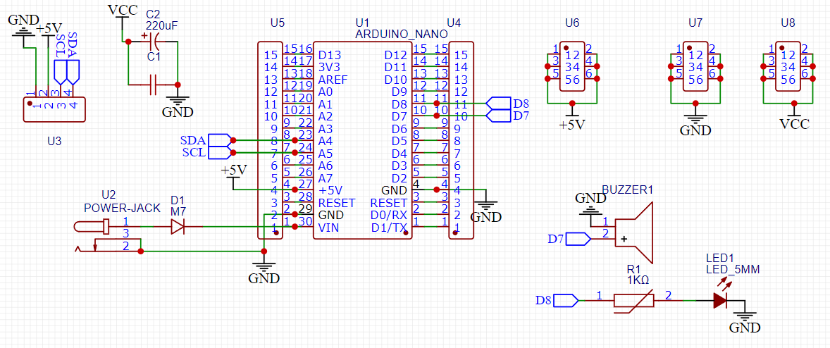
12V is converted into 5 volts by Arduino 5v linear voltage regulator, which supplies the power to the whole of the unit. I chose this because Arduino's AMS1117 5v regulator has a max current rating of 1 Ampere which is enough for peripherals. But there is always an option to connect external 5v for heavy loads. Headers are available for connection with microcontroller, and power supply ports for connecting different sensors and devices.
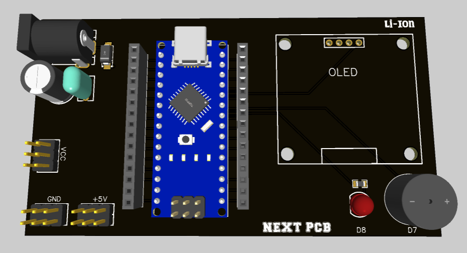
PCB Design:
The PCB is made accordingly to utilize all the available functions, Because of the standard I2C port on the right side, any sensor or display can be plugged directly which works on the same interface and has pin compatibility. On board led used as an indicator, I separate out the PCB led from D13 pin led, which is available on the Arduino main board to increase the functionality. The power headers are available at lower side of the board, VCC, 5V and common ground to connect different sensors and devices. Download the PCB files from here.
NextPCB is a China based PCB manufacturer having 15 years of experience in this field. NextPCB provides the PCB and assembly technologies with the highest quality standards, and the lowest manufacturer direct prices.
Testing:
Here are a few testing examples to know if everything soldered is working properly. If there is any dry solder joint remaining then the display may show some jittering and noise. Same with the digital pins of the Arduino.
To see the Gerber files try HQDFM free online PCB Gerber viewer. Which may help you get an idea about the PCB specs, orientation and components requirement.
Example 1: Testing the screen
Here is an example from Adafruit which shows some animations using the Adafruit OLed library. These animations are fast and If there is any misconnection or dry solder joint it may create some noise in the screen operation.
Sample code:
#include <SPI.h>
#include <Wire.h>
#include <Adafruit_GFX.h>
#include <Adafruit_SSD1306.h>
#define SCREEN_WIDTH 128 // OLED display width, in pixels
#define SCREEN_HEIGHT 32 // OLED display height, in pixels
#define OLED_RESET     -1 // Reset pin # (or -1 if sharing Arduino reset pin)
#define SCREEN_ADDRESS 0x3C ///< See datasheet for Address; 0x3D for 128x64, 0x3C for 128x32
Adafruit_SSD1306 display(SCREEN_WIDTH, SCREEN_HEIGHT, &Wire, OLED_RESET);
#define NUMFLAKES 10 // Number of snowflakes in the animation example
#define LOGO_HEIGHT 16
#define LOGO_WIDTH 16
static const unsigned char PROGMEM logo_bmp[] =
{ 0b00000000, 0b11000000,
0b00000001, 0b11000000,
0b00000001, 0b11000000,
0b00000011, 0b11100000,
0b11110011, 0b11100000,
0b11111110, 0b11111000,
0b01111110, 0b11111111,
0b00110011, 0b10011111,
0b00011111, 0b11111100,
0b00001101, 0b01110000,
0b00011011, 0b10100000,
0b00111111, 0b11100000,
0b00111111, 0b11110000,
0b01111100, 0b11110000,
0b01110000, 0b01110000,
0b00000000, 0b00110000 };
void setup() {
Serial.begin(9600);
// SSD1306_SWITCHCAPVCC = generate display voltage from 3.3V internally
if(!display.begin(SSD1306_SWITCHCAPVCC, SCREEN_ADDRESS)) {
Serial.println(F("SSD1306 allocation failed"));
for(;;); // Don't proceed, loop forever
}
display.display();
delay(2000); // Pause for 2 seconds
// Clear the buffer
display.clearDisplay();
// Draw a single pixel in white
display.drawPixel(10, 10, SSD1306_WHITE);
display.display();
delay(2000);
testdrawline();      // Draw many lines
testdrawrect();      // Draw rectangles (outlines)
testfillrect();      // Draw rectangles (filled)
testdrawcircle();    // Draw circles (outlines)
testfillcircle();    // Draw circles (filled)
// Invert and restore display, pausing in-between
display.invertDisplay(true);
delay(1000);
display.invertDisplay(false);
delay(1000);
testanimate(logo_bmp, LOGO_WIDTH, LOGO_HEIGHT); // Animate bitmaps
}
void loop() {
}
void testdrawline() {
int16_t i;
display.clearDisplay(); // Clear display buffer
for(i=0; i<display.width(); i+=4) {
display.drawLine(0, 0, i, display.height()-1, SSD1306_WHITE);
display.display(); // Update screen with each newly-drawn line
delay(1);
}
for(i=0; i<display.height(); i+=4) {
display.drawLine(0, 0, display.width()-1, i, SSD1306_WHITE);
display.display();
delay(1);
}
delay(250);
display.clearDisplay();
for(i=0; i<display.width(); i+=4) {
display.drawLine(0, display.height()-1, i, 0, SSD1306_WHITE);
display.display();
delay(1);
}
for(i=display.height()-1; i>=0; i-=4) {
display.drawLine(0, display.height()-1, display.width()-1, i, SSD1306_WHITE);
display.display();
delay(1);
}
delay(250);
display.clearDisplay();
for(i=display.width()-1; i>=0; i-=4) {
display.drawLine(display.width()-1, display.height()-1, i, 0, SSD1306_WHITE);
display.display();
delay(1);
}
for(i=display.height()-1; i>=0; i-=4) {
display.drawLine(display.width()-1, display.height()-1, 0, i, SSD1306_WHITE);
display.display();
delay(1);
}
delay(250);
display.clearDisplay();
for(i=0; i<display.height(); i+=4) {
display.drawLine(display.width()-1, 0, 0, i, SSD1306_WHITE);
display.display();
delay(1);
}
for(i=0; i<display.width(); i+=4) {
display.drawLine(display.width()-1, 0, i, display.height()-1, SSD1306_WHITE);
display.display();
delay(1);
}
delay(2000); // Pause for 2 seconds
}
void testdrawrect(void) {
display.clearDisplay();
for(int16_t i=0; i<display.height()/2; i+=2) {
display.drawRect(i, i, display.width()-2*i, display.height()-2*i, SSD1306_WHITE);
display.display(); // Update screen with each newly-drawn rectangle
delay(1);
}
delay(2000);
}
void testfillrect(void) {
display.clearDisplay();
for(int16_t i=0; i<display.height()/2; i+=3) {
// The INVERSE color is used so rectangles alternate white/black
display.fillRect(i, i, display.width()-i*2, display.height()-i*2, SSD1306_INVERSE);
display.display(); // Update screen with each newly-drawn rectangle
delay(1);
}
delay(2000);
}
void testdrawcircle(void) {
display.clearDisplay();
for(int16_t i=0; i<max(display.width(),display.height())/2; i+=2) {
display.drawCircle(display.width()/2, display.height()/2, i, SSD1306_WHITE);
display.display();
delay(1);
}
delay(2000);
}
void testfillcircle(void) {
display.clearDisplay();
for(int16_t i=max(display.width(),display.height())/2; i>0; i-=3) {
// The INVERSE color is used so circles alternate white/black
display.fillCircle(display.width() / 2, display.height() / 2, i, SSD1306_INVERSE);
display.display(); // Update screen with each newly-drawn circle
delay(1);
}
delay(2000);
}
#define XPOS 0 // Indexes into the 'icons' array in function below
#define YPOS 1
#define DELTAY 2
void testanimate(const uint8_t *bitmap, uint8_t w, uint8_t h) {
int8_t f, icons[NUMFLAKES][3];
// Initialize 'snowflake' positions
for(f=0; f< NUMFLAKES; f++) {
icons[f][XPOS]   = random(1 - LOGO_WIDTH, display.width());
icons[f][YPOS]   = -LOGO_HEIGHT;
icons[f][DELTAY] = random(1, 6);
Serial.print(F("x: "));
Serial.print(icons[f][XPOS], DEC);
Serial.print(F(" y: "));
Serial.print(icons[f][YPOS], DEC);
Serial.print(F(" dy: "));
Serial.println(icons[f][DELTAY], DEC);
}
for(;;) { // Loop forever...
display.clearDisplay(); // Clear the display buffer
// Draw each snowflake:
for(f=0; f< NUMFLAKES; f++) {
display.drawBitmap(icons[f][XPOS], icons[f][YPOS], bitmap, w, h, SSD1306_WHITE);
}
display.display(); // Show the display buffer on the screen
delay(200);        // Pause for 1/10 second
// Then update coordinates of each flake...
for(f=0; f< NUMFLAKES; f++) {
icons[f][YPOS] += icons[f][DELTAY];
// If snowflake is off the bottom of the screen...
if (icons[f][YPOS] >= display.height()) {
// Reinitialize to a random position, just off the top
icons[f][XPOS]   = random(1 - LOGO_WIDTH, display.width());
icons[f][YPOS]   = -LOGO_HEIGHT;
icons[f][DELTAY] = random(1, 6);
}
}
}
}
Example 2: Testing the Peripherals
The second example is a DHT temperature measurement which measures the data after every 2 seconds giving a blink to the led. This will test all the other operations of the circuit like USB controls, buzzer, power supply unit and headers. Try now the PCB services offered by NextPCB.
Sample code:
#include <DHT11.h>
// Create an instance of the DHT11 class.
// - For Arduino: Connect the sensor to Digital I/O Pin 2.
DHT11 dht11(2);
void setup()
{
Serial.begin(9600);
}
void loop()
{
// Attempt to read the temperature value from the DHT11 sensor.
int temperature = dht11.readTemperature();
if (temperature != DHT11::ERROR_CHECKSUM && temperature != DHT11::ERROR_TIMEOUT)
{
Serial.print("Temperature: ");
Serial.print(temperature);
Serial.println(" °C");
}
else
{
Serial.println(DHT11::getErrorString(temperature));
}
digitalWrite(8, HIGH); // turn the LED on (HIGH is the voltage level)
delay(100); // wait for a second
digitalWrite(8, LOW); // turn the LED off by making the voltage LOW
// Wait for 1 seconds before the next reading.
delay(2000);
}