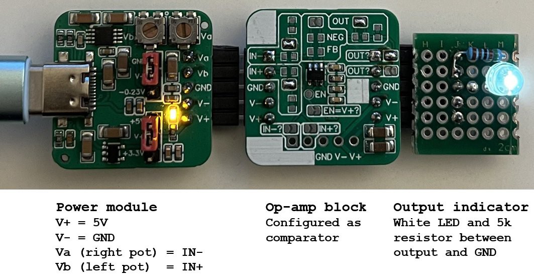
The op-amp block is a tool for rapid prototyping of analog electronics. It consists of easily swappable modules that include an entire analog block, e.g., an amplifier, a comparator, or a simple active filter. These modules are built from a single small PCB that includes TI’s OPA357 op-amp, decoupling capacitors, and pads for components to configure the op-amp, such as to implement a negative feedback network.
Details
Op-amp Block
The op-amp blocks are breadboard-friendly but can also be plugged into one another for developing complex circuits with minimal additional components through a simple 5 pin interface. For input, the interface consists of IN-, IN+, GND, V-, and V+. On the output side you can select via solder jumpers where the block’s output goes to the following block – either to IN- or to IN+. Plus it passes through the power pins, such that all blocks share the same power supply.
An additional input interface is present on the bottom of the block, with the IN- and IN+ disconnected by default, so power can be injected into an analog chain leaving the inputs available for sensors. The bottom IN pins can be enabled by solder jumpers, for example to provide a fixed bias voltage somewhere in the analog chain.
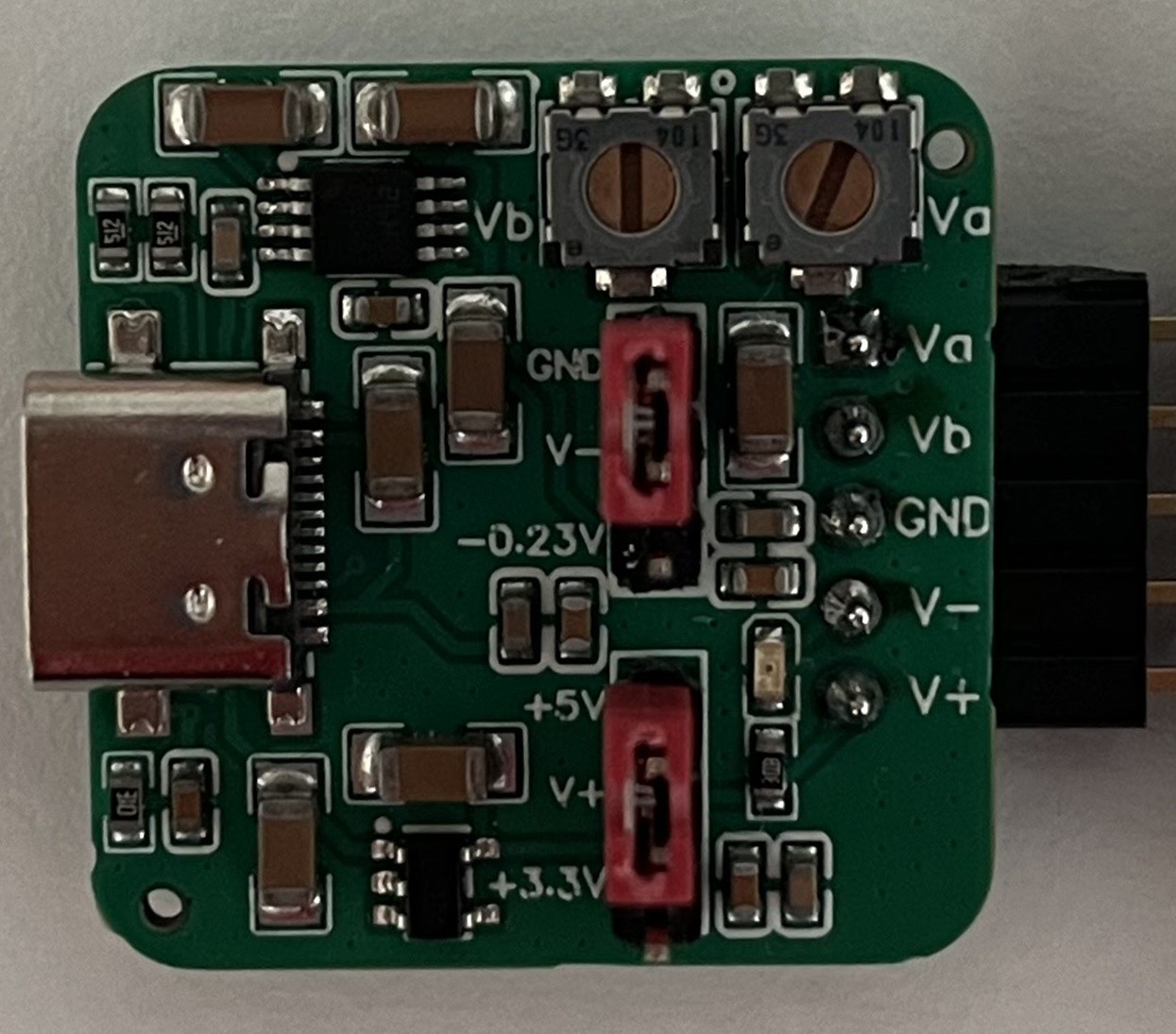
Power module
A Type-C power module can supply voltages to the analog chain from any USB port. It provides a choice for V+ of either 3.3V or 5V, and for V- either GND or -0.23V (when you need the output reach true 0V). The OPA357 is specified for supply voltages between 2.7V and 5.5V so any combination of V+ and V- will keep it happy. Two potentiometers on the power module can provide fixed biases for IN- and/or IN+.
---8<---8<--- Previous version description ---8<---8<---
For the radiation detector I’m working on I had to do my first analog design. I knew it wouldn’t be very straight-forward and I’d be going back and forth between simulations in PSpice for TI and trying out circuit prototypes. The detector analog front-end needs to be fairly fast and most interesting op-amps come in tiny packages. I’d also want to avoid long traces and high parasitic capacitances in the feedback loop for this type of prototyping.
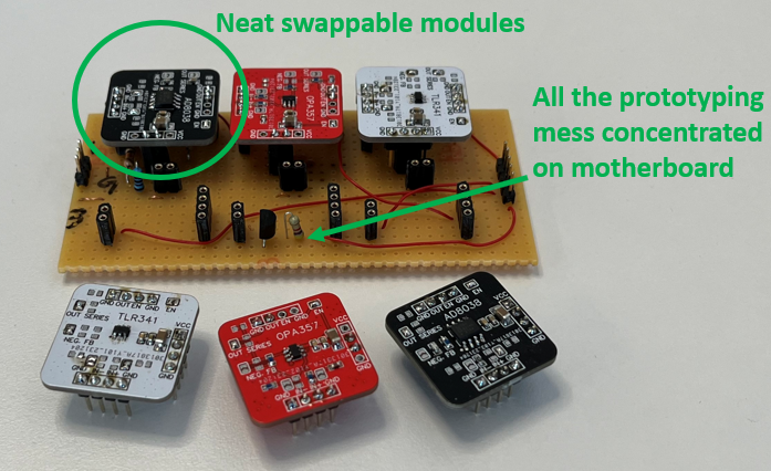
My solution was to make some versatile plug-in modules with a few different op-amps that I can just swap out during testing. Specs:
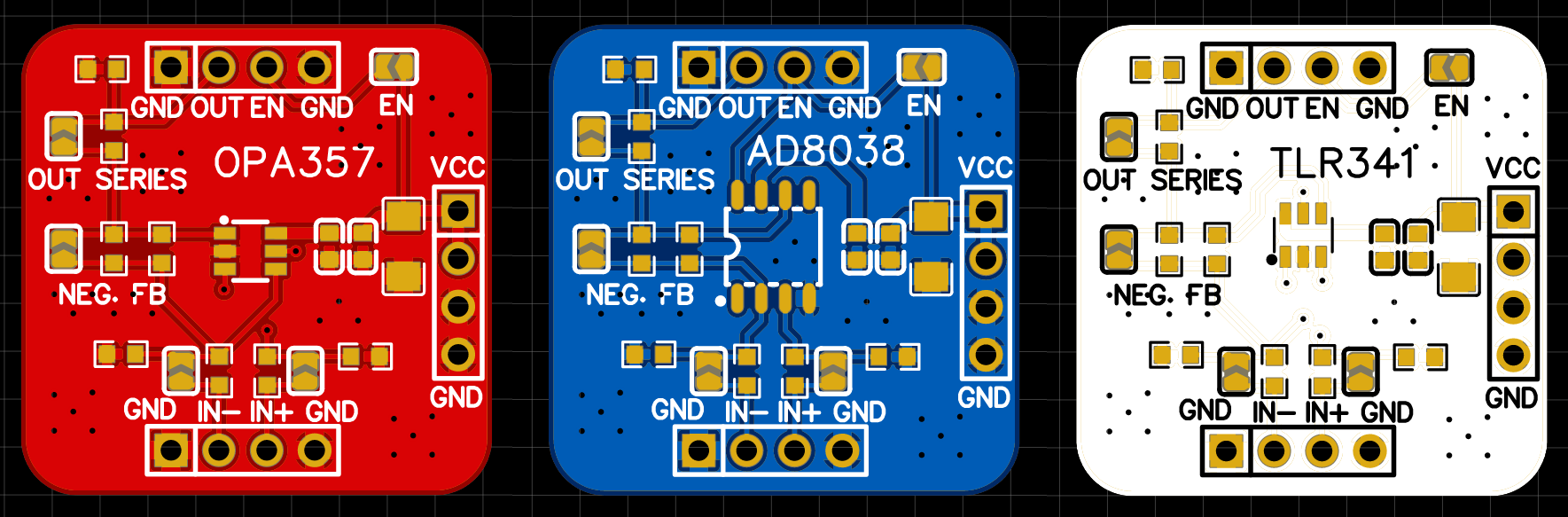
3 different op-amps supported (on different PCBs): OPA357, AD8038, and TLR341. Op-amp pinouts being what they are you can actually fit a lot more
Decoupling capacitors on the module
Same pin-out for all 3 boards to easily swap them out
Flexibility to implement different feedback networks on the module using 0603 components and solder bridges
Op-amp enable pin accessible, but can also be solder bridged to Vcc
Then I could also have the same circuit but in several versions (e.g. with different gains) that I could swap out. This allowed me to independently figure out the block diagram and each amplifier's feedback network.
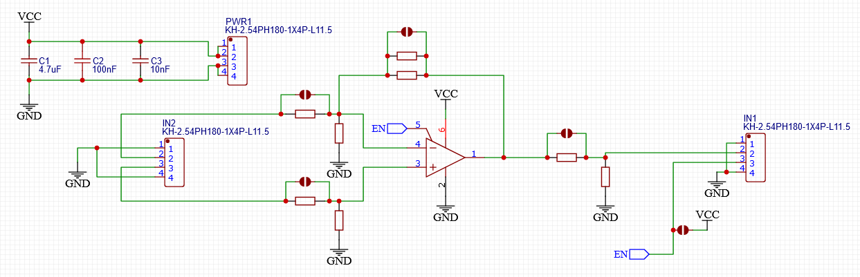
Schematic
The design allows connecting inputs and output directly (through solder bridges) to the op-amp, or through 0603 components. Only negative feedback is implemented in the schematic, but if you're willing to have some flying leads you can do pretty much anything :)
PCB versions
I made 3 versions for different types of op-amps. By far the one I used most is the OPA357 as it's a very fast and flexible general-purpose chip.
Use case
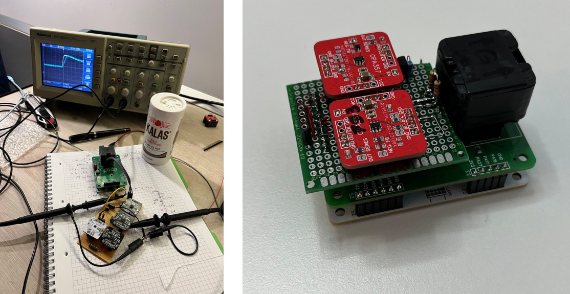
I used these modules to develop the analog section of the radiation detector I'm working on. They allowed me to decouple the "block diagram" mess located on a perfboard, from each block's paramers (e.g. gain, shaping time).
On the left there's a very early prototype while I was trying to figure out the block diagram. On the right is a late stage prototype once the block diagram was sorted out, such that I could swap modules out for optimization.
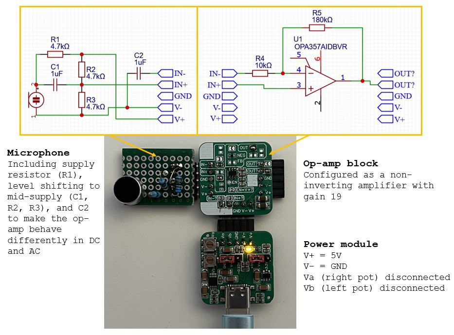
An electret microphone fed from 5V will supply a signal on the order of 100mV. To boost it up to a few volts (to feed it into an Arduino, for example) it needs amplification. We can do that with the op-amp block.
The microphone board contains the circuitry to generate a signal centered around 2.5V and also capacitor C2 which decouples the op-amp feedback network (R5 and R4) from V-. This makes the op-amp behave like a voltage follower at DC (R4 disconnected from V-) and as an amplifier with gain 19 at AC. So, it will amplify the audio waveform, but not the 2.5V that it rides on.
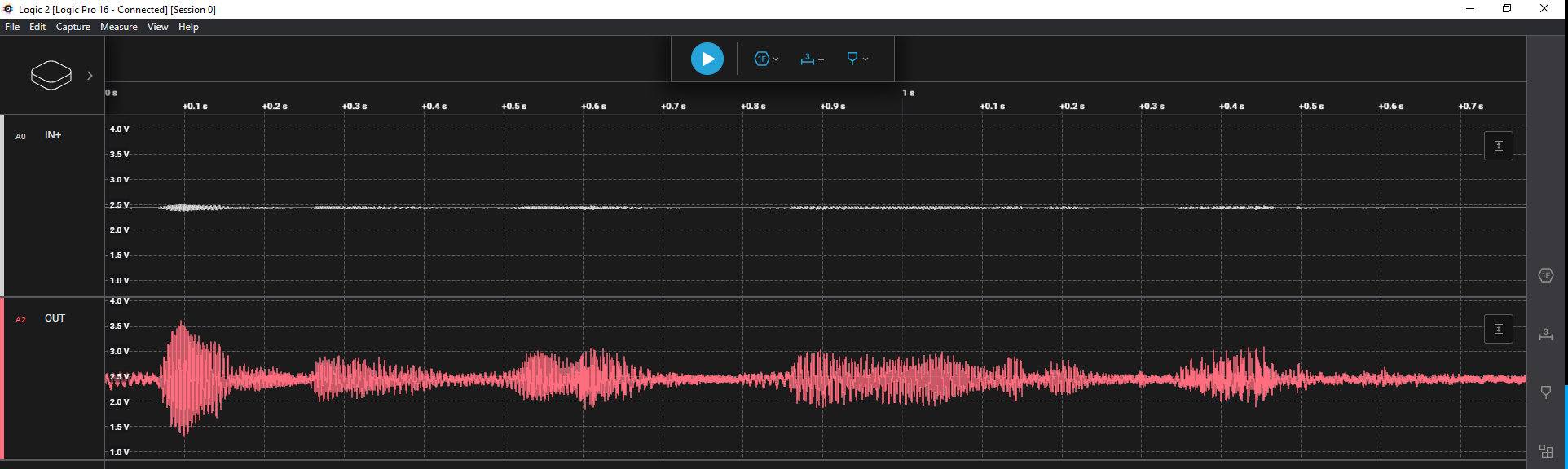
Top trace is microphone output and bottom one is op-amp output.
The huge open-loop gain of op-amps (at least one billion in the case of the OPA357) makes them virtually unusable as amplifiers without some form of feedback network to lower the gain to a reasonable and predictable value. There is one exception where are used in open-loop mode, and that is as comparators. Any minute difference between IN+ and IN- gets amplified so much that it saturates the output either close to the positive rail or to the negative one.
Just like what Jon said, I've toyed with the idea but you actually went and did it! Definitely would make troubleshooting loops a lot easier. Probably has a value as an educational component too!
Oh it helped a lot! My initial design used a much more complex setup with a transimpedance amplifier using the AD8038 but I couldn't get that working properly for me. It took me just 2 days over the holidays to redesign, simulate, implement and verify a new analog section.
And just like you suggest, once I had these I started wondering about educational applications -- like filters for a whistle detector, or a preamp for a pesky PIR sensor.
Very cool! I had this idea several times, but you went through and completed it! :D I note that there are connectors on 3 sides. This would be slightly more breadboard friendly if the connector was only on two sides, or one side? DIL/SIL style.
Thanks! Yeah, I totally agree that a 2nd version should stick to having connectors on just 2 sides. I'm also thinking of making it possible to just plug boards into eachother and not necessarily need a motherboard
 mihai.cuciuc
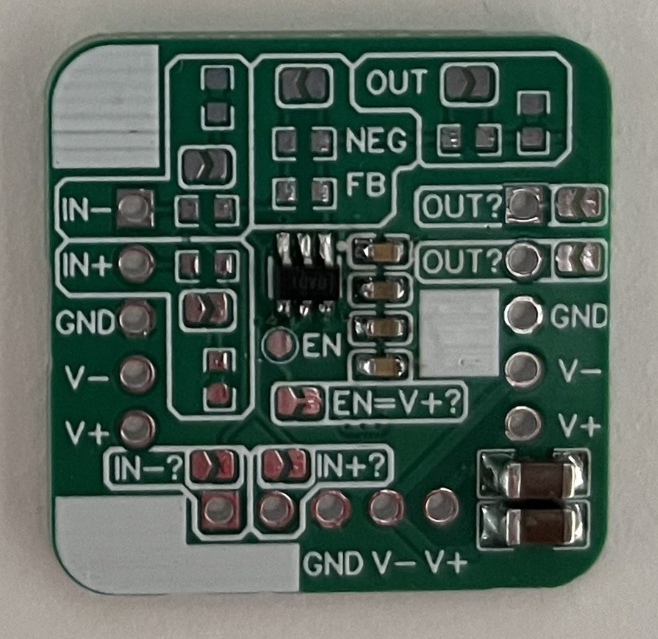


 A. J. Griggs
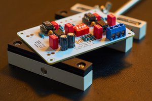
 Maxim Fyodorov
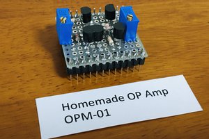
 Mitsuru Yamada
Whatever you do, don't call it LEGO. They're an absolute shit company that has a fetish for suing people.