Close
0%
0%

Live TEMP Meter with XIAO and AHT10

TEMP meter was created and installed on a motorcycle to show the temperature and humidity in real time in the vicinity.

Public Chat
Similar projects worth following
Here's something COOL, a temperature and humidity monitoring meter based on the AHT10 that measures the parameters related to the surrounding air temperature and humidity.

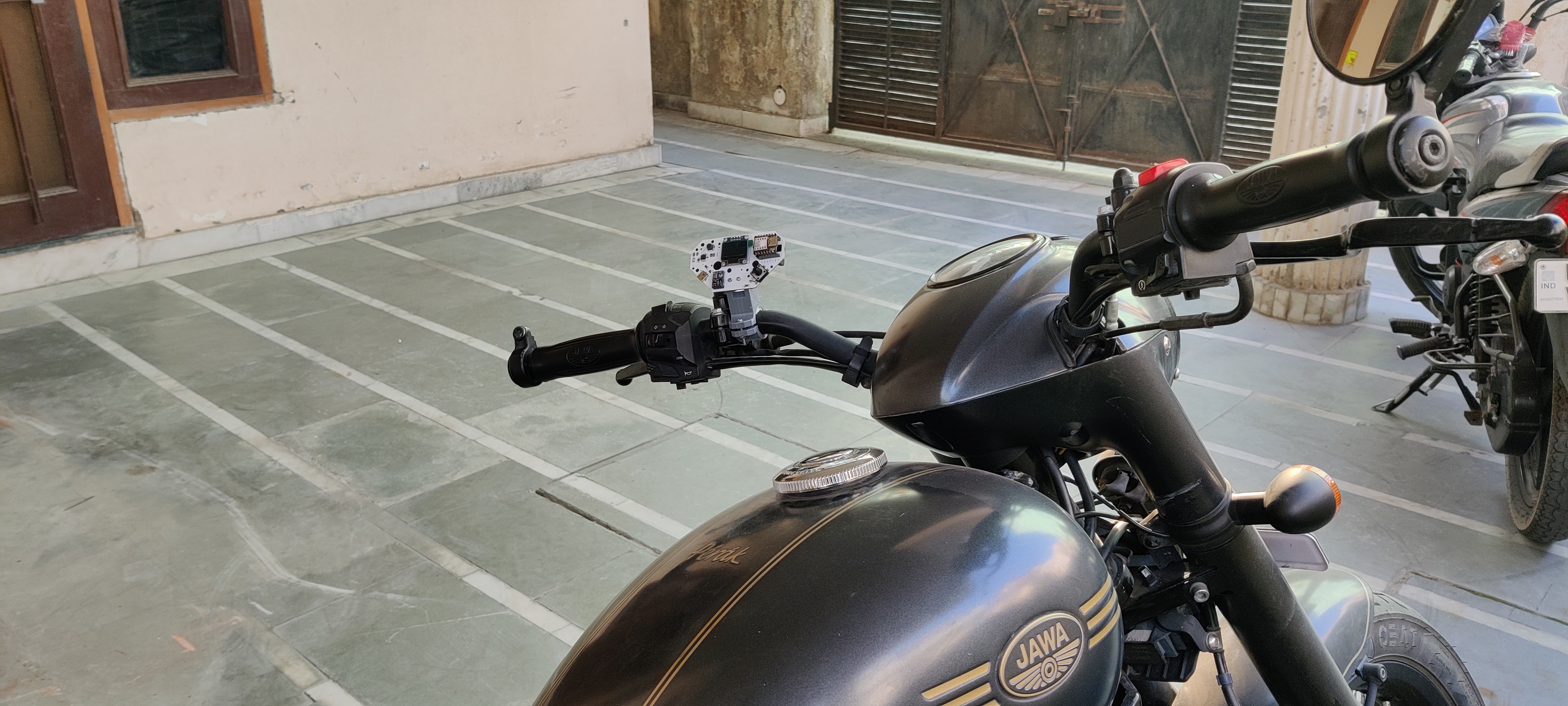
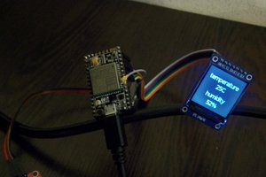
The objective of this project was to build a meter that I could simply put on my motorcycle so that I could visit XYZ locations and take temperature readings without having to rely on inaccurate data from my smartphone.

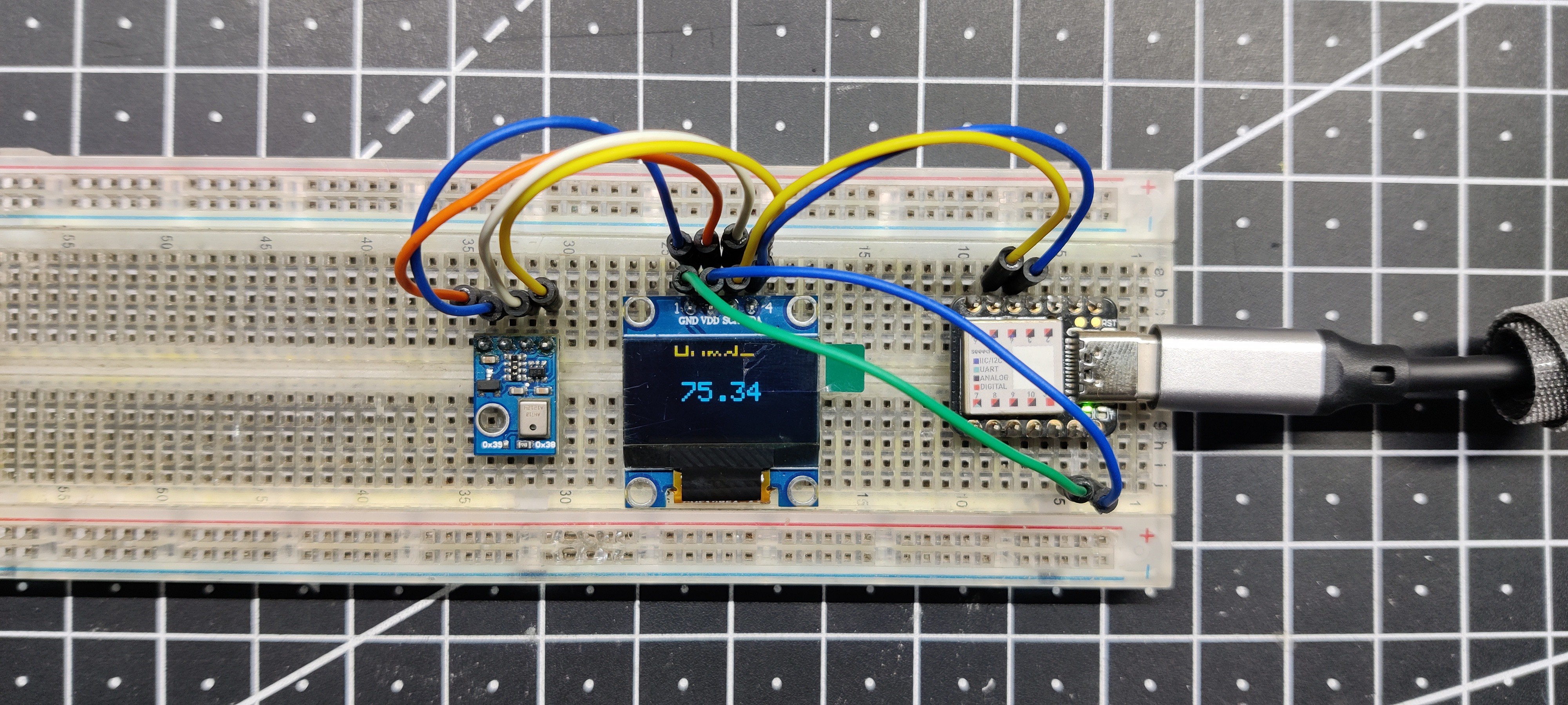
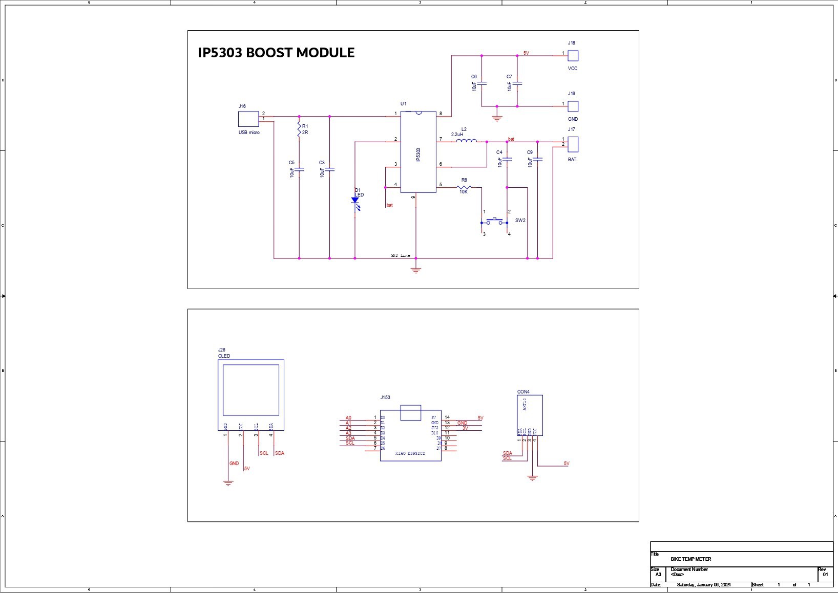
Here, the XIAO MCU is connected to an AHT10 sensor for data collection, and the SSD1306 display is used to show the temperature and humidity measurements.

This circuit was mounted onto the bike's handle using a 3D printed holder, and it has a built-in 3.7V 2600mAh Li-ion battery for power.

3mf - 61.03 kB - 02/14/2024 at 11:26

Download

3mf - 56.12 kB - 02/14/2024 at 11:26

Download

3mf - 53.30 kB - 02/14/2024 at 11:26

Download

fusion - 4.68 MB - 02/14/2024 at 11:26

Download

Adobe Portable Document Format - 181.61 kB - 02/14/2024 at 11:26

Preview
Download

  • 1 × XIAO M0 Microcontroller
  • 1 × AHT10 Sensor
  • 1 × Custom PCB
  • 1 × IP5306 IC
  • 1 × 10uF Capacitors

View all 10 components

  • 1
    AHT10 Sensor with XIAO Setup

    The AHT10 Temp and Humidity Sensor Module is being used in this project, and it is a compact and highly accurate sensor designed to measure temperature and humidity in various applications. The module integrates a high-performance AHT10 sensor chip, which utilizes a capacitive sensing element to detect changes in temperature and humidity.

    It provides reliable and precise measurements with a temperature accuracy of ±0.3°C and a humidity accuracy of ±2% RH.

    The AHT10 module operates between 1.6V and 6V, which is ideal if we use an external 5V source to power this sensor along with the SSD1306 display and XIAO M0 Board.

    The AHT10 sensor was connected to the Seeed XIAO M0 dev board in a basic breadboard setup for this project. An SSD1306 OLED screen was utilized to display the temperature and humidity readings.

    CONNECTIONS-

    • 5V of XIAO gets connected to VCC of both the display and AHT10 Sensor
    • GND is connected with GND
    • SDA of Both the display and AHT10 gets connected to A4 IO Pin
    • SCL of Both the display and AHT10 gets connected to A5 IO Pin
  • 2
    CODE

    Here's the code that was used in this project, and its a simple one.

    This code essentially demonstrates how to use the AHT10 sensor library to read temperature and humidity, display the results on an OLED screen, and handle errors. The delays between measurements are implemented to avoid heating the sensor

    #include <Wire.h>
    #include <AHTxx.h>
    
    
    #include <Adafruit_SSD1306.h>
    #include <Adafruit_GFX.h>
    
    #define OLED_WIDTH 128
    #define OLED_HEIGHT 64
    
    #define OLED_ADDR   0x3C
    Adafruit_SSD1306 display(OLED_WIDTH, OLED_HEIGHT);
    
    
    float ahtValue;                               //to store T/RH result
    
    AHTxx aht10(AHTXX_ADDRESS_X38, AHT1x_SENSOR); //sensor address, sensor type
    
    
    void setup()
    {
      #if defined(ESP8266)
      WiFi.persistent(false);  //disable saving wifi config into SDK flash area
      WiFi.forceSleepBegin();  //disable AP & station by calling "WiFi.mode(WIFI_OFF)" & put modem to sleep
      #endif
    
      display.begin(SSD1306_SWITCHCAPVCC, OLED_ADDR);
      display.clearDisplay();
    
      Serial.begin(115200);
      Serial.println();
      
      while (aht10.begin() != true) //for ESP-01 use aht10.begin(0, 2);
      {
        Serial.println(F("AHT1x not connected or fail to load calibration coefficient")); //(F()) save string to flash & keeps dynamic memory free
    
        delay(5000);
      }
    
      Serial.println(F("AHT10 OK"));
    
      //Wire.setClock(400000); //experimental I2C speed! 400KHz, default 100KHz
    }
    
    
    void loop()
    {
      /* DEMO - 1, every temperature or humidity call will read 6-bytes over I2C, total 12-bytes */
      Serial.println();
      Serial.println(F("DEMO 1: read 12-bytes"));
    
      ahtValue = aht10.readTemperature(); //read 6-bytes via I2C, takes 80 milliseconds
    
      display.clearDisplay();
      display.setTextSize(2);
      display.setTextColor(WHITE);
      display.setCursor(30, 0);
      display.println(F("Temp-"));
    
    //  Serial.print(F("Temperature...: "));
      
      if (ahtValue != AHTXX_ERROR) //AHTXX_ERROR = 255, library returns 255 if error occurs
      {
    
      display.setTextSize(2);
      display.setTextColor(WHITE);
      display.setCursor(35, 25);
      display.println(ahtValue);
      display.display();
    //    Serial.print(ahtValue);
       
      }
      else
      {
        printStatus(); //print temperature command status
    
        if   (aht10.softReset() == true) Serial.println(F("reset success")); //as the last chance to make it alive
        else                             Serial.println(F("reset failed"));
      }
    
      delay(2000); //measurement with high frequency leads to heating of the sensor, see NOTE
    
      ahtValue = aht10.readHumidity(); //read another 6-bytes via I2C, takes 80 milliseconds
    
      display.clearDisplay();
      display.setTextSize(2);
      display.setTextColor(WHITE);
      display.setCursor(30, 0);
      display.println(F("Humd-"));
      
      
    //  Serial.print(F("Humd-"));
      
      if (ahtValue != AHTXX_ERROR) //AHTXX_ERROR = 255, library returns 255 if error occurs
      {
    
      display.setTextSize(2);
      display.setTextColor(WHITE);
      display.setCursor(35, 25);
      display.println(ahtValue);
      display.display();
        
        
     //   Serial.println(F(" +-2%"));
      }
      else
      {
        printStatus(); //print humidity command status
      }
    
      delay(2000); //measurement with high frequency leads to heating of the sensor, see NOTE
    
      /* DEMO - 2, temperature call will read 6-bytes via I2C, humidity will use same 6-bytes */
      Serial.println();
      Serial.println(F("DEMO 2: read 6-byte"));
    
      ahtValue = aht10.readTemperature(); //read 6-bytes via I2C, takes 80 milliseconds
    
      Serial.print(F("Temperature: "));
      
      if (ahtValue != AHTXX_ERROR) //AHTXX_ERROR = 255, library returns 255 if error occurs
      {
        Serial.print(ahtValue);
        Serial.println(F(" +-0.3C"));
      }
      else
      {
        printStatus(); //print temperature command status
      }
    
      ahtValue = aht10.readHumidity(AHTXX_USE_READ_DATA); //use 6-bytes from temperature reading, takes zero milliseconds!!!
    
      Serial.print(F("Humidity...: "));
      
      if (ahtValue != AHTXX_ERROR) //AHTXX_ERROR = 255, library returns 255 if error occurs
      {
        Serial.print(ahtValue);
        Serial.println(F(" +-2%"));
      }
      else
      {
        printStatus(); //print temperature command status not humidity!!! RH measurement use same 6-bytes from T measurement
      }
    
      delay(10000); //recomended polling frequency 8sec..30sec
    }
    
    void printStatus()
    {
      switch (aht10.getStatus())
      {
        case AHTXX_NO_ERROR:
          Serial.println(F("no error"));
          break;
    
        case AHTXX_BUSY_ERROR:
          Serial.println(F("sensor busy, increase polling time"));
          break;
    
        case AHTXX_ACK_ERROR:
          Serial.println(F("sensor didn't return ACK, not connected, broken, long wires (reduce speed), bus locked by slave (increase stretch limit)"));
          break;
    
        case AHTXX_DATA_ERROR:
          Serial.println(F("received data smaller than expected, not connected, broken, long wires (reduce speed), bus locked by slave (increase stretch limit)"));
          break;
    
        case AHTXX_CRC8_ERROR:
          Serial.println(F("computed CRC8 not match received CRC8, this feature supported only by AHT2x sensors"));
          break;
    
        default:
          Serial.println(F("unknown status"));    
          break;
      }
    }
  • 3
    PCB DESIGN

    The next step of this project was to put everything together to create a basic PCB that would contain all of the components we used to create the breadboard version, in addition to a lithium cell with a charge discharge circuit to power the XIAO module, display, and sensor.

    First, we construct the schematic, which is divided into two main sections: the MCU part, which has an XIAO microcontroller paired to an SSD1306 OLED screen and an AHT10 sensor, and the power supply section, which has a standard IP5306 IC arrangement.

    Let's have a look at the power supply section first.

    The power management IC (IP5306) being utilized here is a popular boost converter IC that is typically used for power bank applications. It boosts the voltage of lithium cells from 3.7V to a stable 5V/2A so that XYZ USB devices may be powered.

    To charge the lithium cell, we have added a USB Micro B port.

    In order to avoid overcharging or overdischarge, it has low and high cuts for the lithium cell in addition to an onboard battery fuel indicator.

    Checkout few of my projects in which i have used this IC-

    https://www.hackster.io/Arnov_Sharma_makes/the-ultimate-camera-rig-with-portable-display-d4436d

    https://www.hackster.io/Arnov_Sharma_makes/cyber-py-zero-two-fdd889

    https://www.hackster.io/Arnov_Sharma_makes/overengineered-pen-holder-2-0-5c0daf

    Then we have the Microcontroller section, which consists of the XIAO M0 DEV Board connected with an AHT10 sensor and SSD1306 display.

    The VCC of the AHT10 sensor and the display are both connected to the 5V output of the power management IC. Since the AHT10 and Display are both I2C devices, their SDA and SCL are linked in parallel to the D4 and D5 pins of the XIAO, respectively.

    Connections are the same as in the breadboard version.

    After creating the schematic, we created a PCB with the screen in the center, the AHT10 on the left, and the XIAO M0 on the right using the dimensions from the CAD model of this project created in Fusion 360.

View all 11 instructions

Enjoy this project?

Share

Discussions

Similar Projects

Does this project spark your interest?

Become a member to follow this project and never miss any updates