I started with home-assistant (https://www.home-assistant.io/) and integrated a ZigBee network with a conbee II (https://phoscon.de/en/conbee2) stick. I’m mainly using IKEA components, and it works fine. What I like about ZigBee is that the system runs on low power, and a push-button remote switch costs a few bucks at IKEA.
At the same time, I want to integrate other devices into home assistants to get notifications or perform automation. For example, I have a “normal” washing machine in my basement and would like to get a notice when the washing is finished. Of course, I want to do this as simple as possible.
Therefore, I decided to modify an IKEA RODRET wireless dimmer so that external signals can be used to perform key-pressed events. The modification will, of course, invalidate any warranty and maybe even make the use illegal.
First, to open the housing, the hinge of the front plate needs to be unlocked. This is done by pressing the two pins in the battery compartment and pulling the front plate out from the front. The pins must be pressed deeply to unlock it, and a rubber seal around the front plate causes additional resistance.
After that, the board with the input switch can be seen. The board is only fixed by two screws and can be easily removed.
Maybe you noted the six holes under the battery cover. They give access to the clearly labeled programming / debug interface on the PCB without opening the housing.
A simplified schematic is shown in the figure. It shows just the general principle of operation and does not reflect all circuit components. The switches operate by pulling the signal to the ground. The voltage across the open switch corresponds to Vcc, which leads to the conclusion that pull-up resistors are used. The pull-up resistors have a value of approximately 45 kOhm. Pulling the signal line to the ground by the internal switch or an external circuit will be recognized as a pressed switch. Depending on the signal duration, a short press or a hold could be emulated.
Access to the internal 2,2 V Vcc allows the voltage to supply additional low-power circuits. As it is a low-power device, I would assume that only a fraction of a milliampere should be drawn before the power regulator is overloaded. The additional load will, of course, affect the battery life.
Wires are soldered to the well-labeled Vcc and GND connector on the debug port. Additional wires are connected to the switch. If in doubt, a multimeter will help to find the correct pin of the switch. One connector of the switch is connected permanently to GND, and the other side is isolated and only connected to GND if the key is pressed. The cables are attached to this isolated side of the switch.
If you need only the GND signal for your external circuit, you might also get it from the other pin of the switch. That might simplify the cable routing.
The cables must be appropriately routed and flat on the PCB to close the housing again. There is a tight clearance between the top of the PCB and the cover. But if that is done neatly, the switch can kept fully functional. One option might be also to route the cables underneath the PCB. A small hole for the cable can be drilled in the housing.
There are several hints to assemble all parts in the correct orientation again. The most obvious way is to locate the LED and align it with the diffusor on the housing. The “one” symbol of the front plate is also directed towards the LED. And marks on the front plate indicate that it will fit only in one way.
How I optically capture the state of the washing machine will be the next part of this project.


 Hulk
Hulk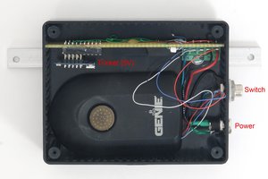
 Involute
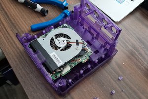
 Jamie
Jamie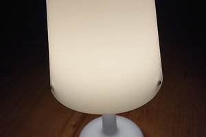
 Stefan-Xp