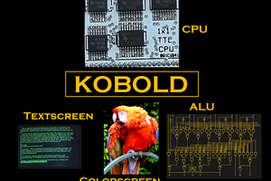
Jara
JaraGeneral Project Features:
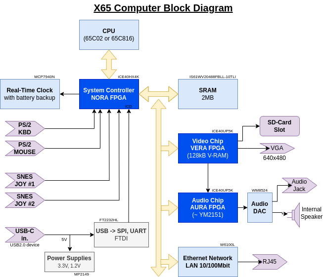
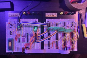
* The CPU is W65C02 (8-bit) or the W65C816 (16-bit; default-preferred). The PCB supports both assembly options.
* Backward software compatibility with the Commander X16 computer. Can run unmodified CX16 ROM for testing purposes (beware: the CX16 ROMs are copyrighted non-free code!).
* Designed with components (chips) that are in production and available from normal electronics parts distributors in 2024, such as Mouser, Farnell, Digikey etc. We avoid obsolete parts.
* Balanced modern/retro design built around the central 65xx CPU supported by semi-ASICs (FPGAs) for system control (NORA), video (VERA) and audio (AURA) generation. The FPGAs are the little ones from the iCE40 series, and coded in verilog. These are modern takes on the "old masters'" designs with ULA, VIA, SID etc. There is no hidden ARM or RISC-V doing heavy lifting in the background.
* Free and open-source design. DIY and hobby-builders friendly. Low-cost to build even in small quantities by individual hackers.
Block Diagram:
Hardware Specification:
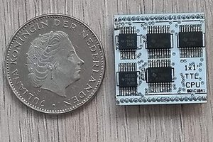
* CPU: W65C02 or W65C816 in the QFP-44 package, running at 8MHz, supplied by 3.3V.
* Memory: 2MB asynchronous SRAM, common for ROM and RAM.
* System controller semi-ASIC, aka north-bridge, aka NORA: Lattice FPGA iCE40HX4K (TQFP-144) handles address decoding, glue logic, PS/2 interfaces, in-circuit debugger and more. "NORA" stands for NORth Adapter, has a similar function like the north bridge in a PC/X86 architecture. NORA takes care of the memory address map and hosts most of the IO registers.
* Two ports for **SNES-style controllers**, handled by NORA.
* Two **PS/2 ports for keyboard and mouse, handled by NORA.
* Colour video output through VGA connector, up to 640x480 pixels. Generated by VERA FPGA: the Video Embedded Retro Adapter, in Lattice FPGA iCE40UP5K. The same is used in Commander X16.
* Stereo audio output through 3.5mm jack port. Sound comes from two sources: FM-synthesis (OPM) by YM2151 clone IKAOPM implemented in AURA FPGA (iCE40UP5K), and Programmable Sound Generator (PSG) available in VERA FPGA. These are digitally mixed in AURA and passed to a DAC. Besides the output jack connector, the sound can be also heard from a small on-board mono speaker.
* SD-card slot supporting SDHC cards (handled by VERA FPGA).
* LAN 10/100Mbps Ethernet port (RJ45) implemented by Wiznet W6100 chip, with hardware-integrated TCP/IP v4/v6 stack.
* Real-time clock (RTC) chip with battery backup.
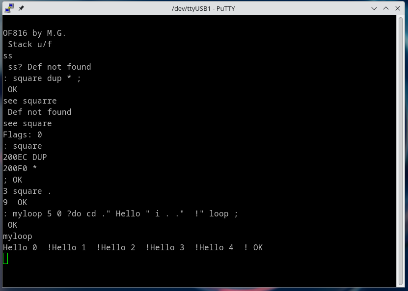
* In-circuit debugger (ICD) integrated with NORA and accessible over the device USB-C port from a host PC running Linux or Windows. The ICD can write all permanent (SPI-Flash) memories in the system, even in a totally empty / bricked state. PC host software is written in Python and should be portable to other fruitful systems besides Linux and Windows. Together with NORA the ICD supports JTAG-like functions like memory poke/dump, CPU stop/step, instruction trace buffer, interrupt forcing/blocking etc.
* Power input 5V from a standard USB Type-C device port. The X65 computer can be powered from a host-PC USB port (for development with ICD), or runs standalone from a common Mains/USB phone charger with just 5V output.
* Single-board PCB 180x100mm, 4-layers.
Do you want to know more?
Find all project data - schematics, kicad projects, FPGA verilog code, documentation - in the github project repository https://github.com/jsyk/x65.

 Tim Ryan
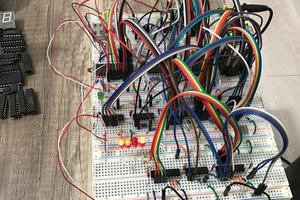
 Dr PEKER