0%
0%
Calculators
Exploration of calculators, their emulation, mechanical aspects such as pretty buttons and quirky displays
 svofski
Become a Hackaday.io member
Already have an account? Log in.
Just one more thing
To make the experience fit your profile, pick a username and tell us what interests you.
Pick an awesome username
hackaday.io/
Your profile's URL: hackaday.io/username. Max 25 alphanumeric characters.
Pick a few interests
Projects that share your interests
People that share your interests

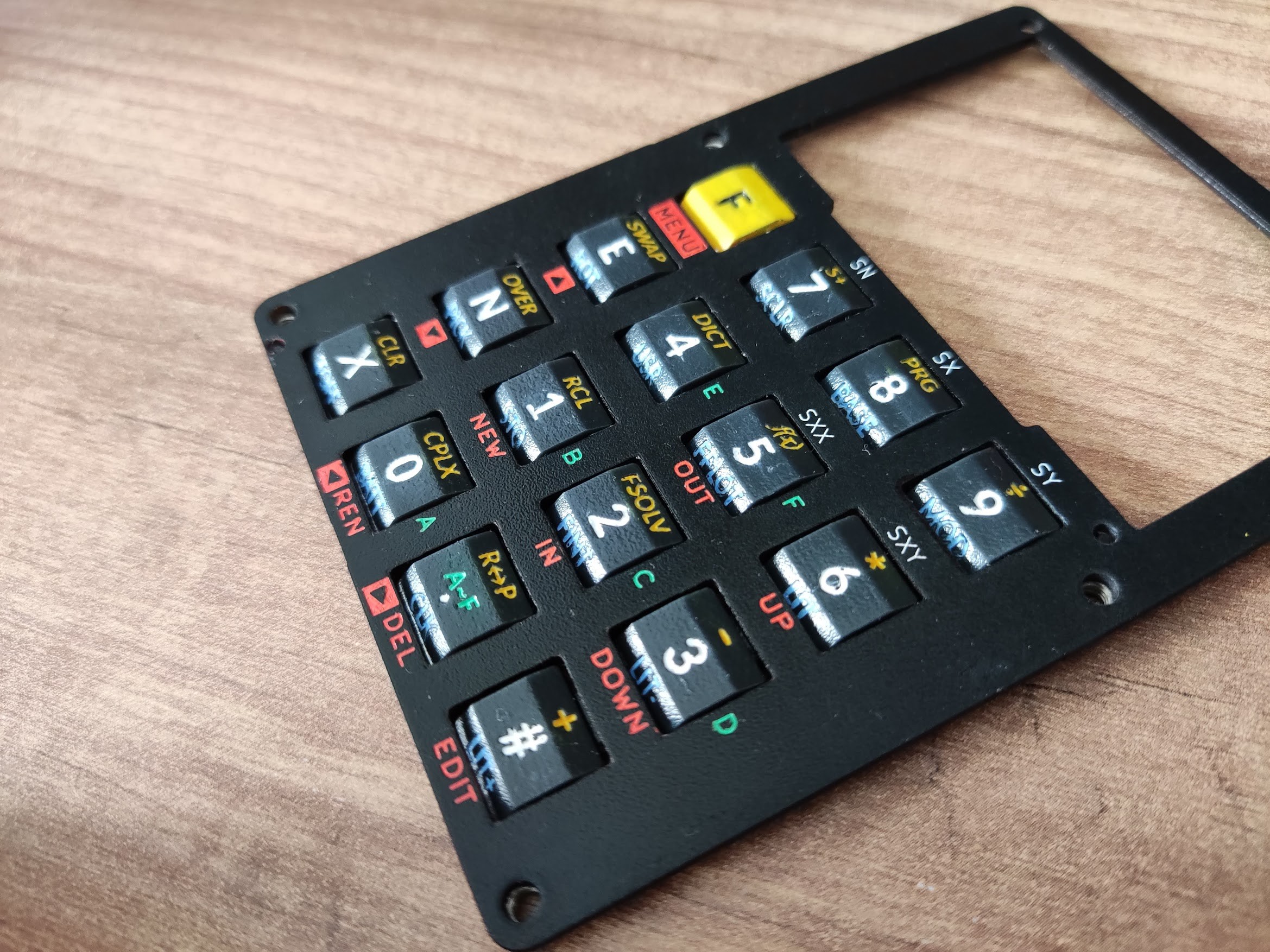
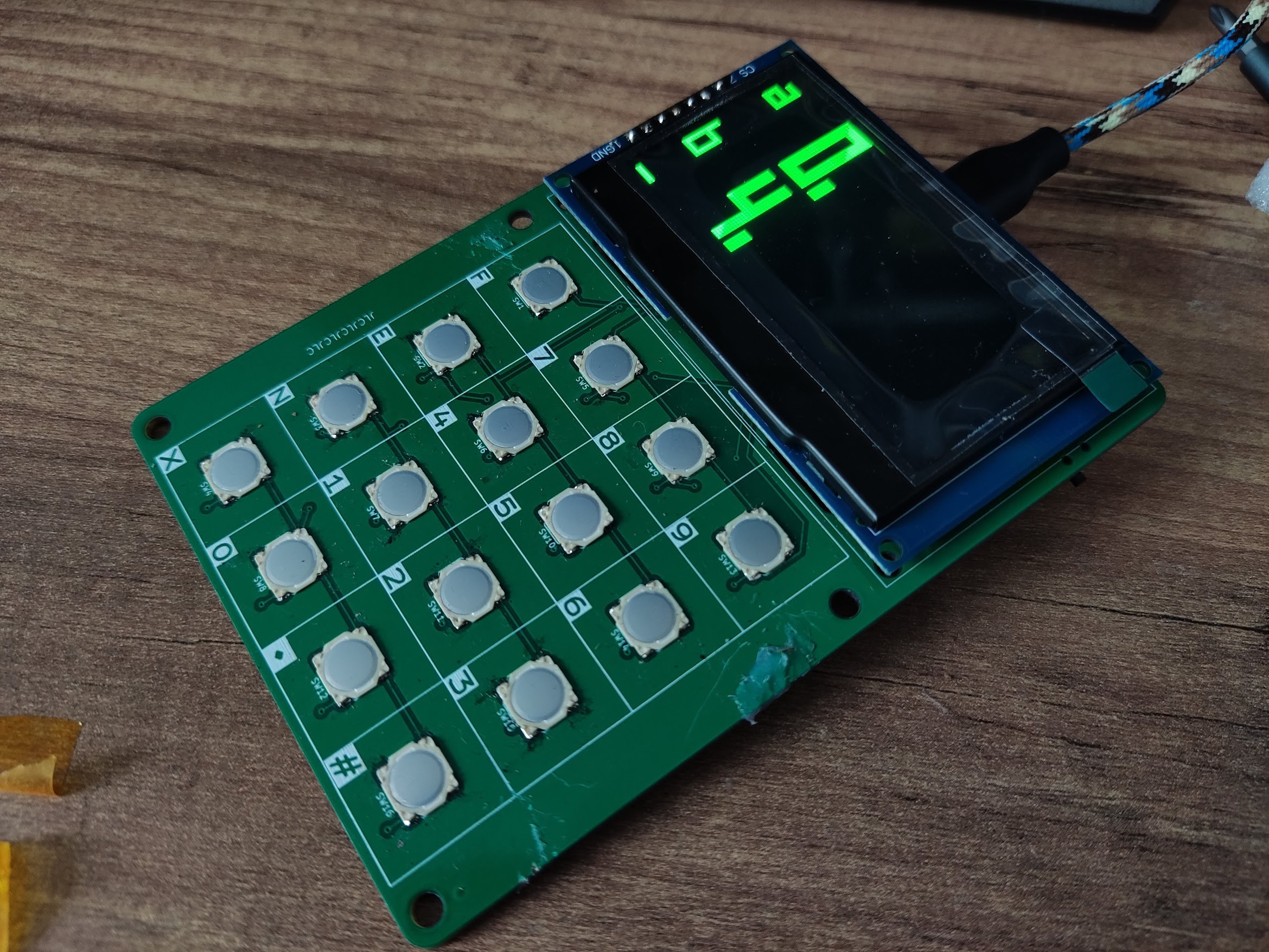
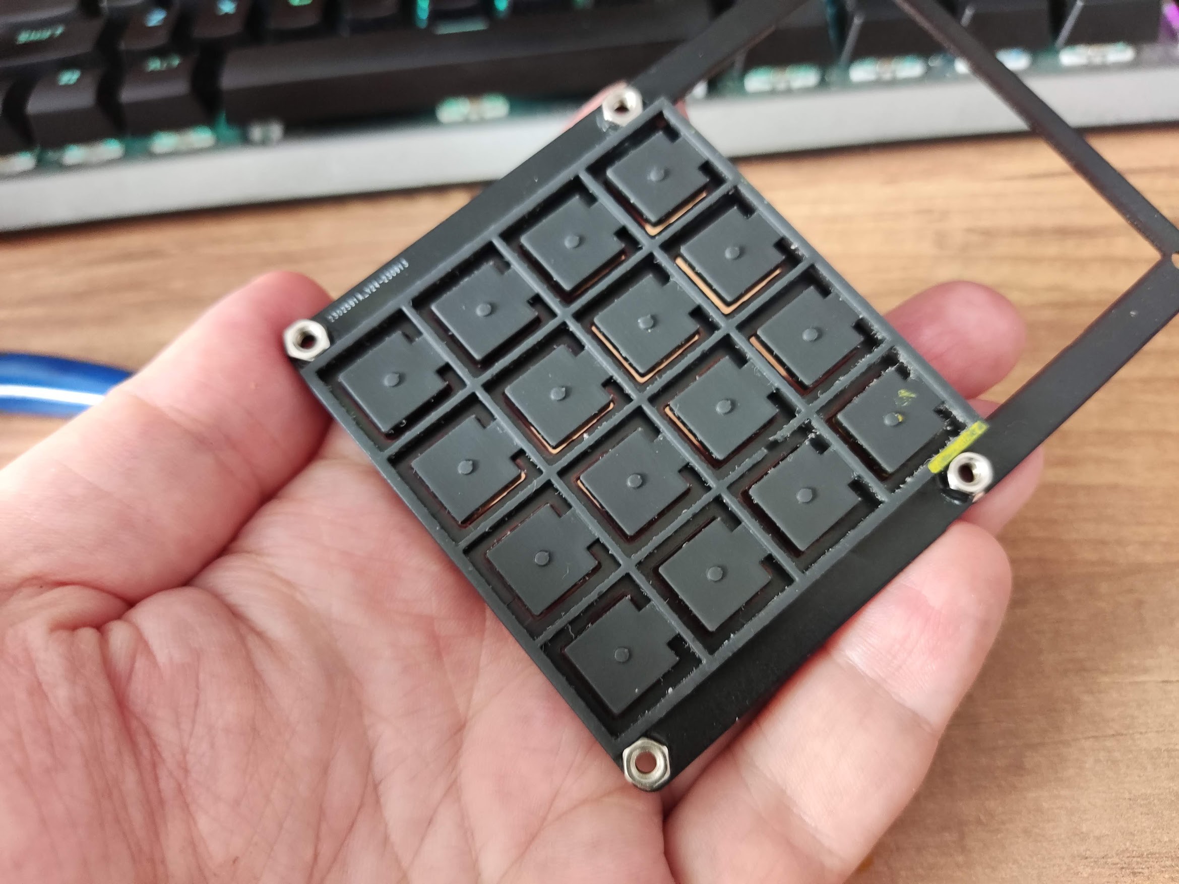
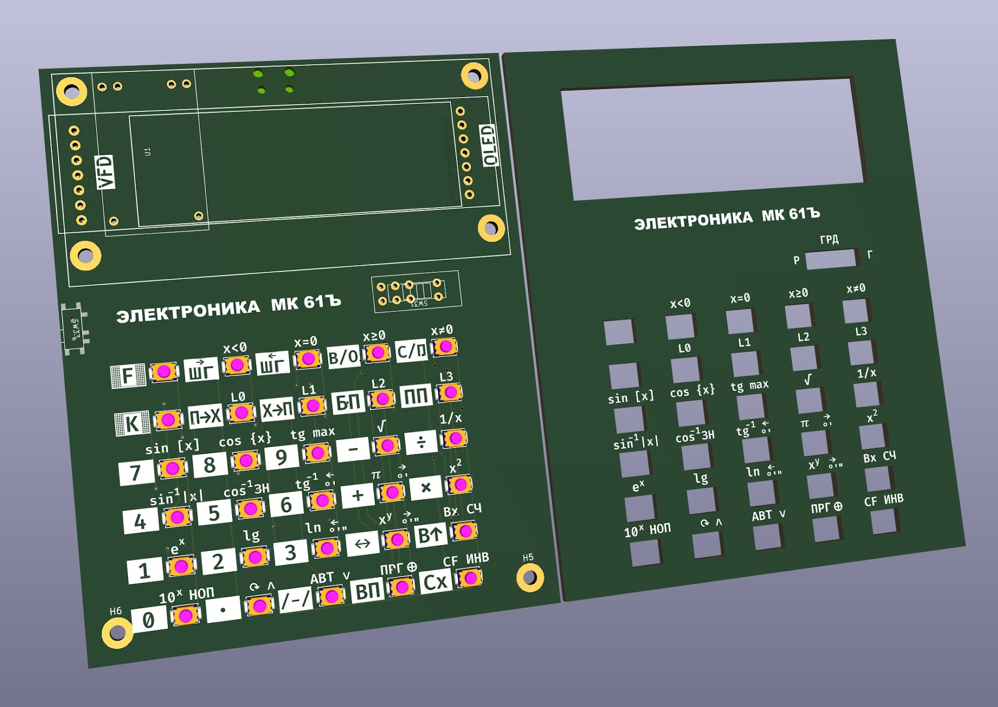 The idea is also to make it usable both as a single-board design, hence the elaborate silkscreen labels for all buttons, and as a sandwich with 3d printed buttons like the IVEE.
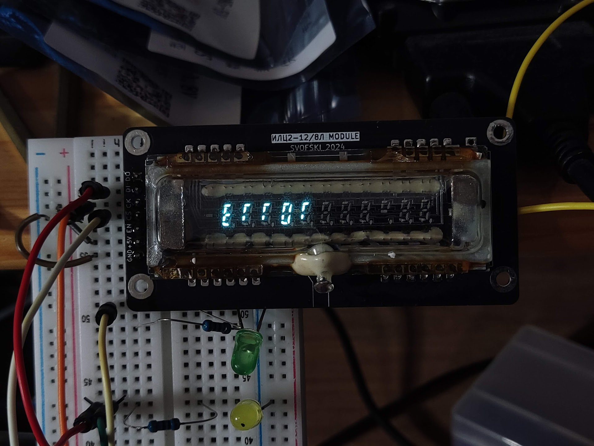
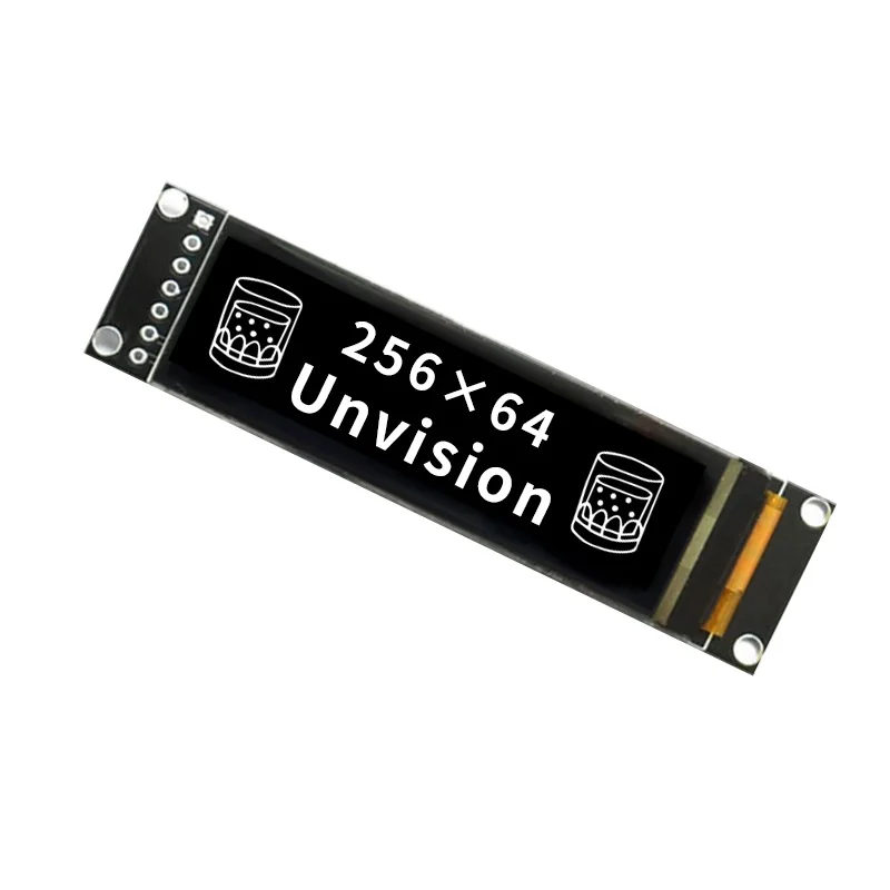 u8g2, which would be my go-to library for driving a small OLED, supports it out of the box. Unfortunately, u8g2 doesn't have any support for grayscale graphics at all. The older u8glib can handle grayscale, but has no support for SH1122. Fortunately I found this nice video:
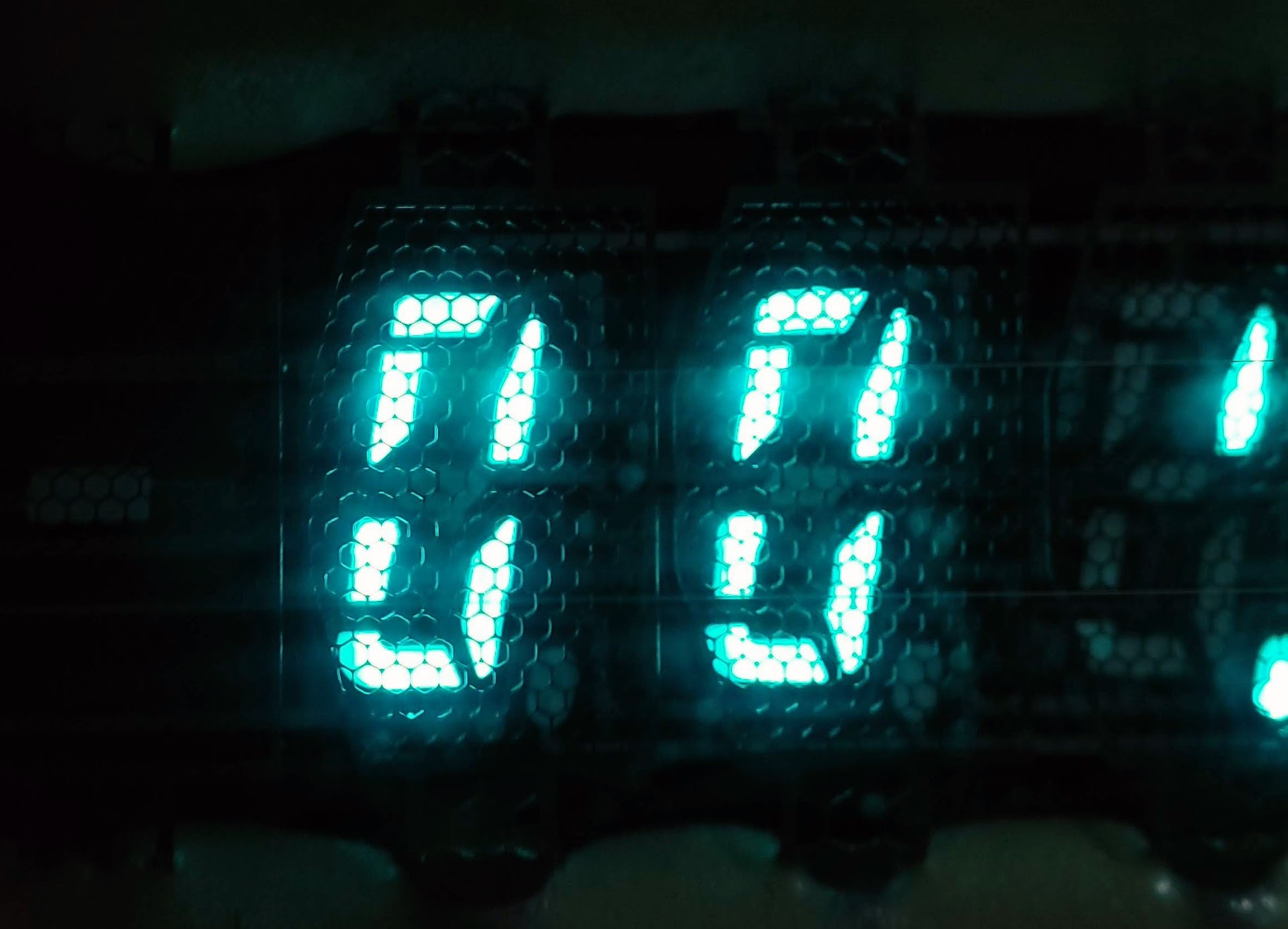
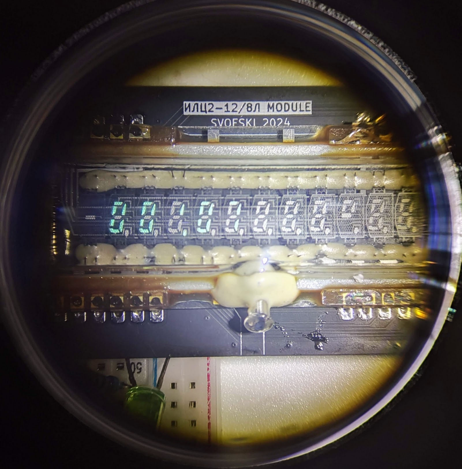
 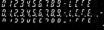 I ruled against rendering individual segments because at this low resolution the segments bleed a little bit into eachother, and it is important for the overall warm and fuzzy look. Note how there's a dedicated minus glyph -- this is because mantissa and exponent sign have a wider, more blocky shape rather than the common middle segment in the main digit pattern.
 For that nice look, non-lit segments should also be visible. Unfortunately, even though this OLED is grayscale, its darkest non-black value is way too bright.
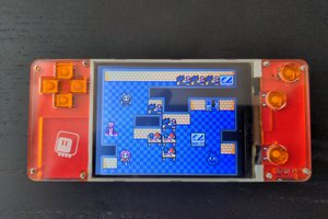
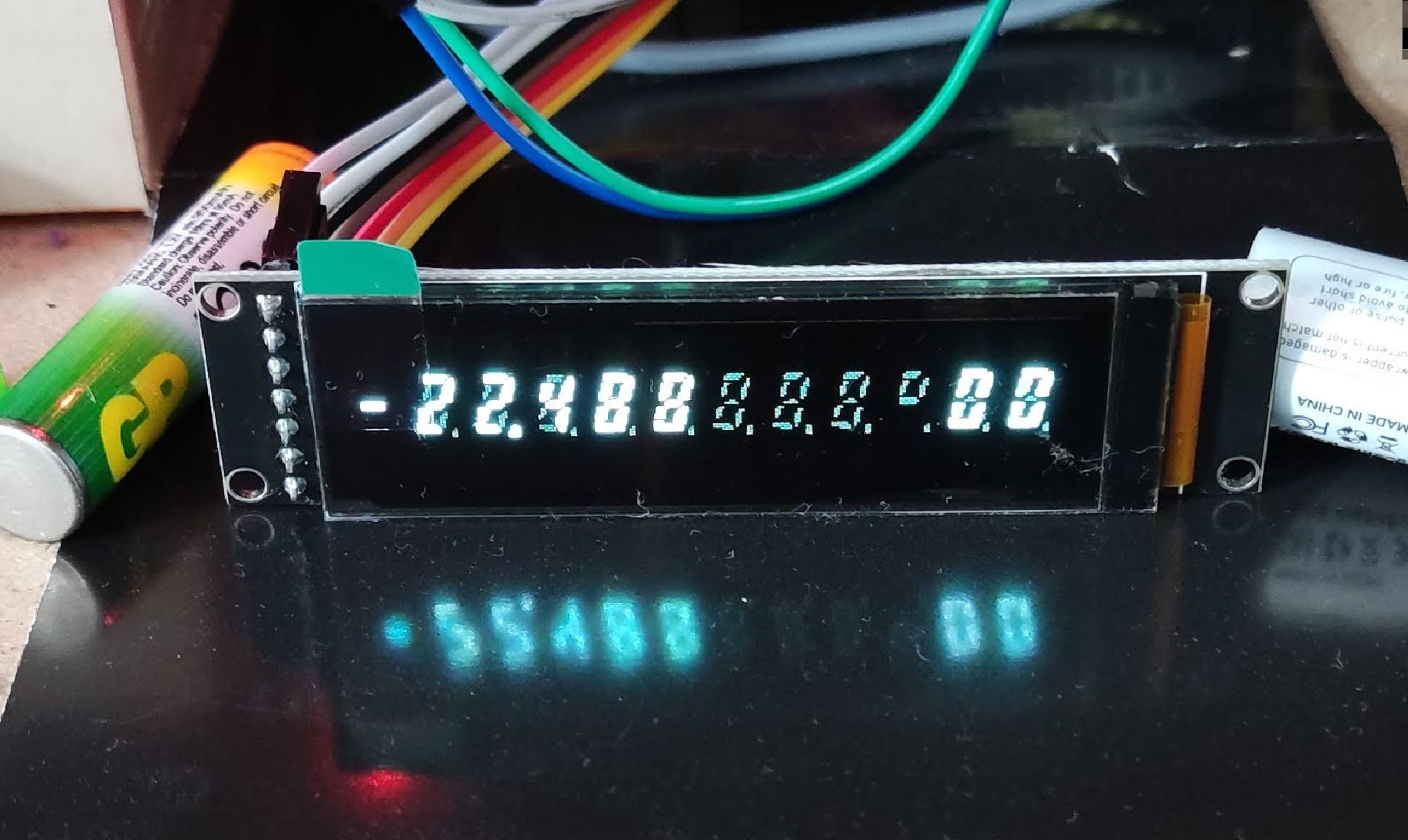 On the photos it tends to look rather crude, but keep in mind that this is a fairly small indicator. I can't see all the sharp detail with a naked eye.
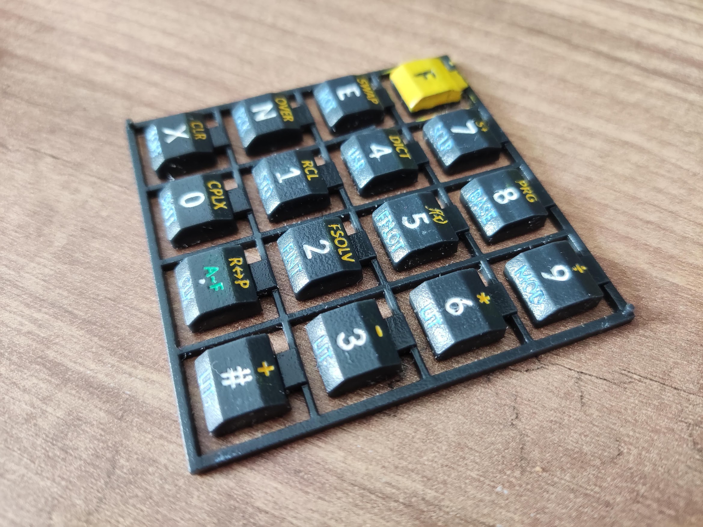
 deʃhipu
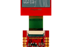
 Markus
 ogdento
 daniel.bryand