Overview
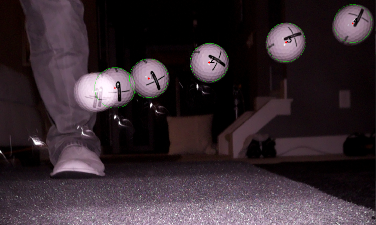
My personal goal has been to use this project as a learning platform for myself. So far, I’ve been able to explore all sorts of software and hardware that I hadn’t worked with previously. I’ve been kid-in-a-candy-store, getting to learn all sorts of new technology, techniques, libraries, and platforms. This has also forced me to spin up on my linear algebra again.
Technologies
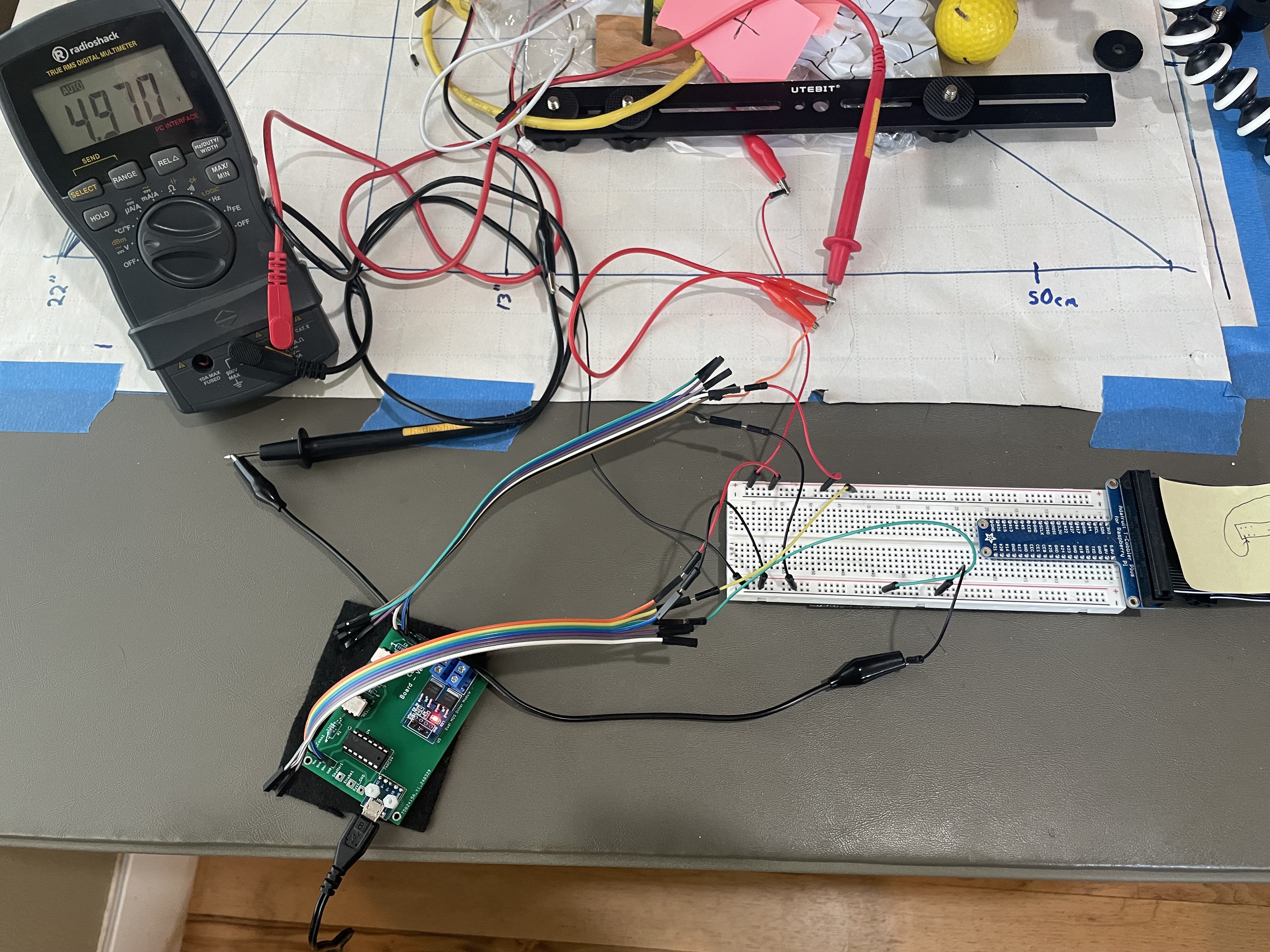
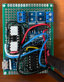
Some of the technologies in use so far are:
- Active-MQ (multi-protocol messaging middleware)
- Apache Jakarta Server Pages (serves the web-based default system GUI)
- Boost (various foundational libraries for logging, multi-threading, thread-safe data structures, command line processing, etc.)
- Debian (Raspbian) Linux (OS)
- JSON (serialization)
- JMS (messaging)
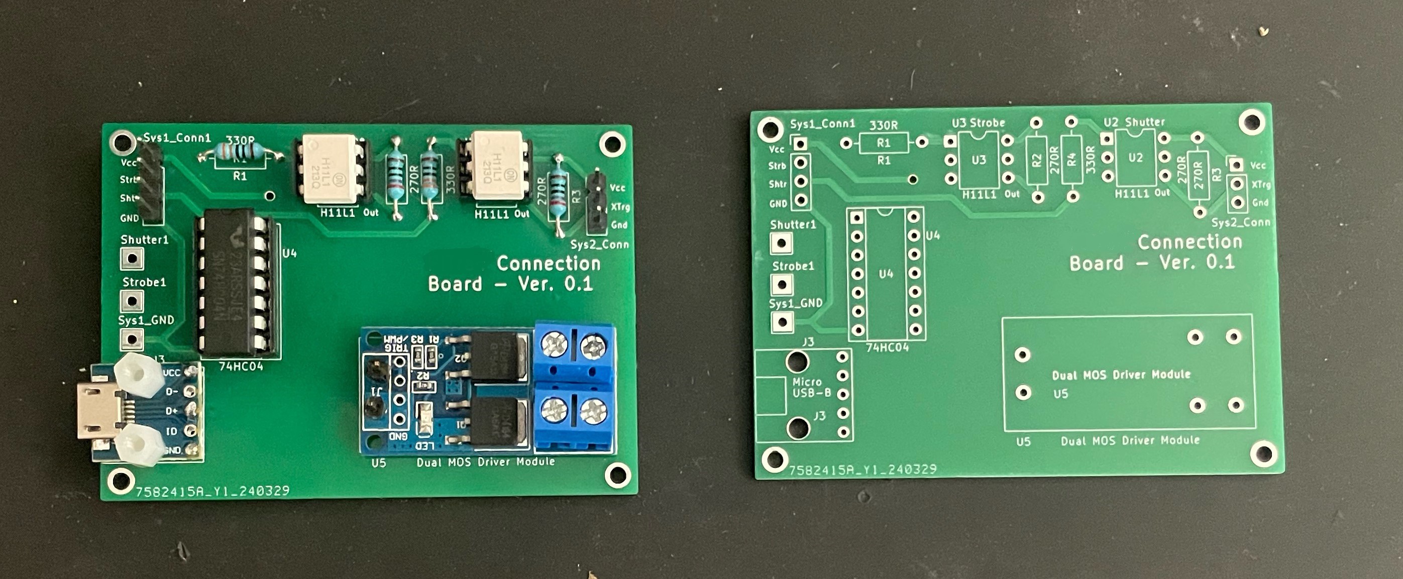
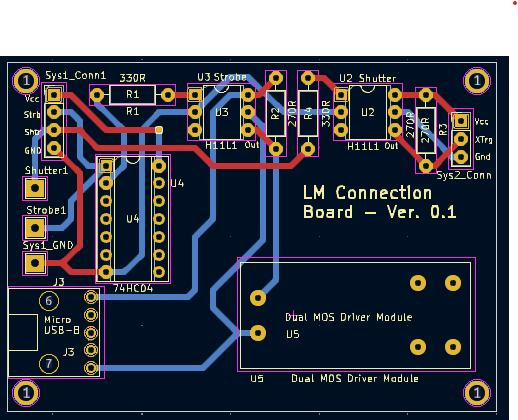
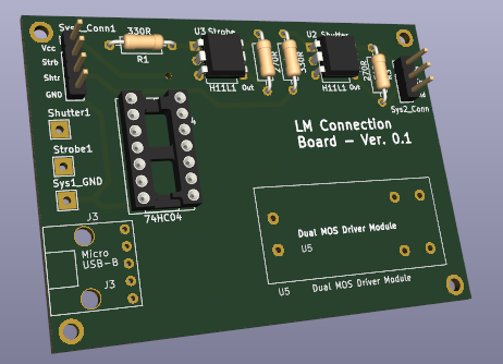
- KiCad (schematic capture and PCB layout)
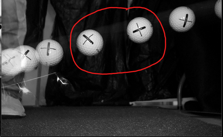
- Libcamera and Libcamera/rpicam-apps App (open-source camera stack & framework)
- Maven (java build automation)
- Meson & Ninja (build tools)
- Msgpack (efficient architecture-independent serialization)
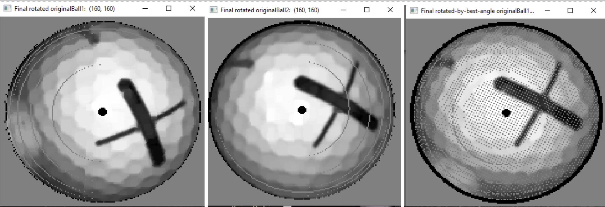
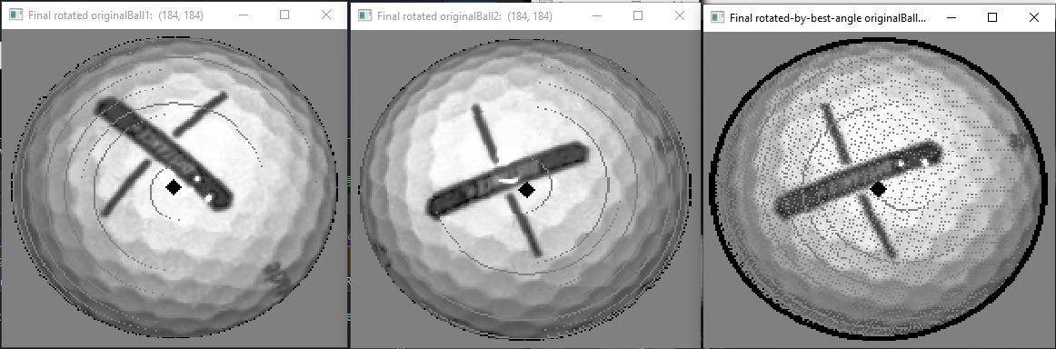
- OpenCV (image processing & filtering, matrix math)
- PiGPIO (GPIO and SPI library)
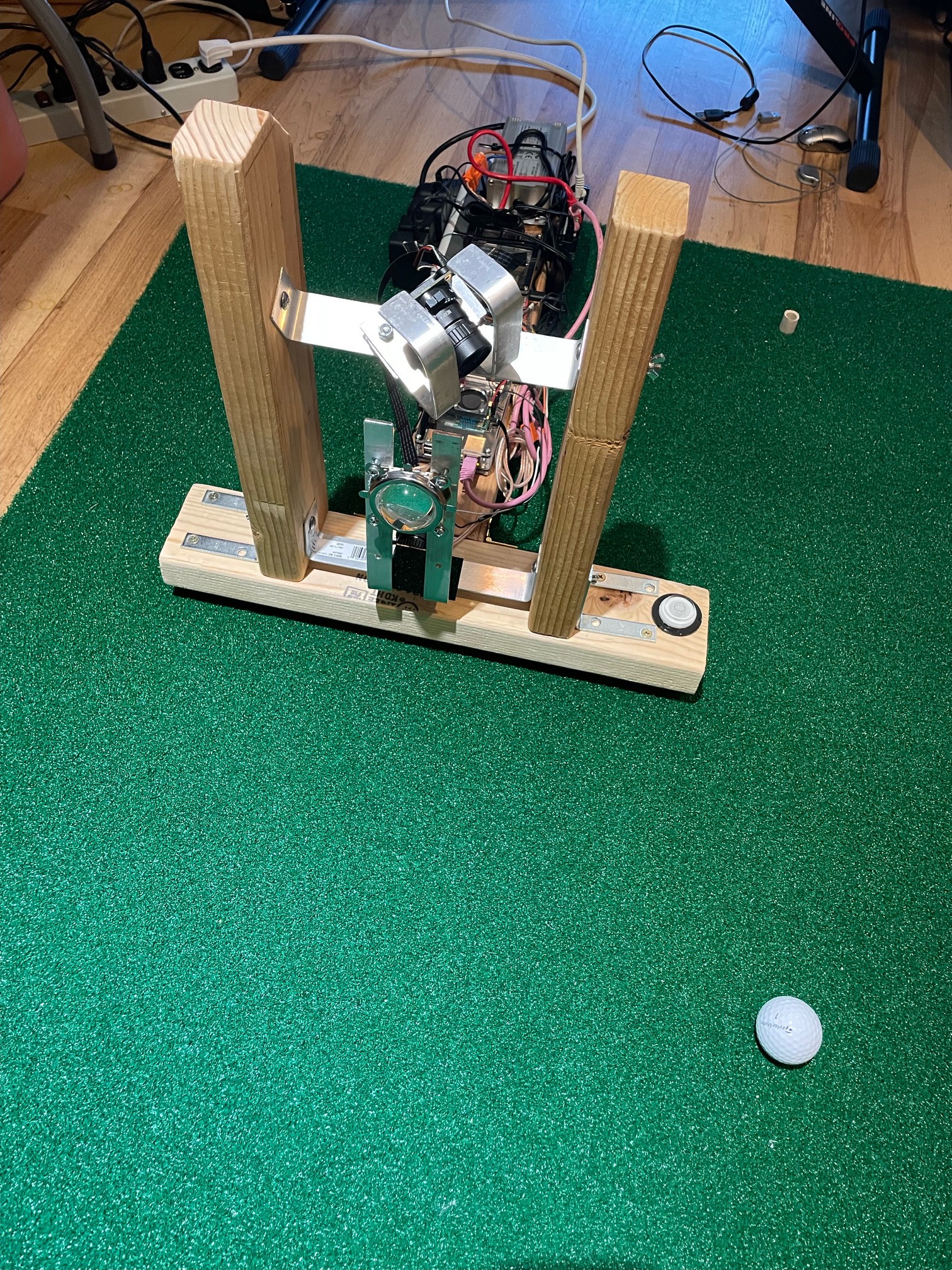
- Raspberry Pi Single-Board Computers
- Tomee (hosts the web-based interface)
- KiCad (Schematic and PCB software)
The software is written almost entirely in C++, with the goal of having the codebase look close to commercial standards in terms of testability, architecture, and documentation. There are some utilities (for functions like camera and lens calibration) that were easier to implement in Python and/or Unix scripts.
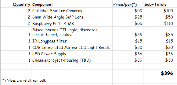
Cost
I’d like to have the entire system cost less than US$300. I’m currently over-budget by about a hundred dollars, but have plans that should bring that price down. For example, the new Raspberry Pi 5 should be able to support both of the system cameras, which could decrease the price by around $50 by avoiding a second Pi.
The high-level parts list at this time:
Additional Project Videos:


 jean
jean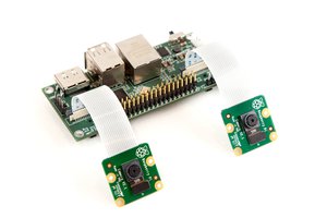
 Eugene
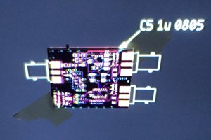
 Ted Yapo
Great stuff and I wanted to comment some relevant info if anyone tries to go down the road of using AI models to help with the prediction. I assume this would lead to being able to make the predictions more accurate with less costly hardware, if some smart people were up to the task.
I found some relevant info from a video where someone uses similar tools to track players on a football field which brought up some interesting resources.
https://www.youtube.com/watch?v=neBZ6huolkg
A dataset of 1400 golf swing videos.
https://www.kaggle.com/datasets/marcmarais/videos-160/data
He uses Yolov8 deep learning object detection model, which seem to be something OpenCV handles already and it seems if anything Yolo runs faster and can be fine tuned.
https://github.com/ultralytics/ultralytics