What is my progress so far?
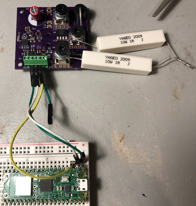
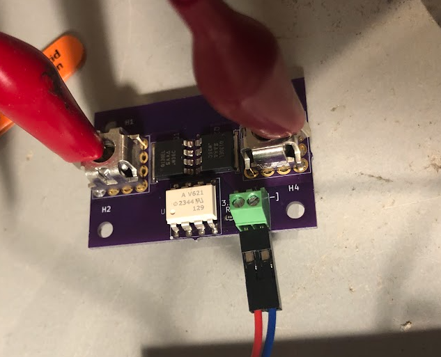
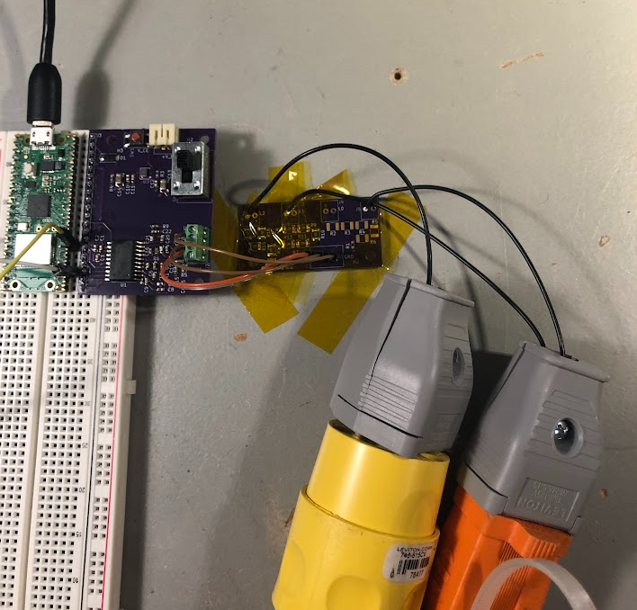
- April 24, 2024 - Built the half-bridge and tested it
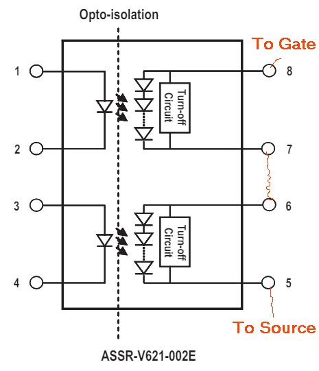
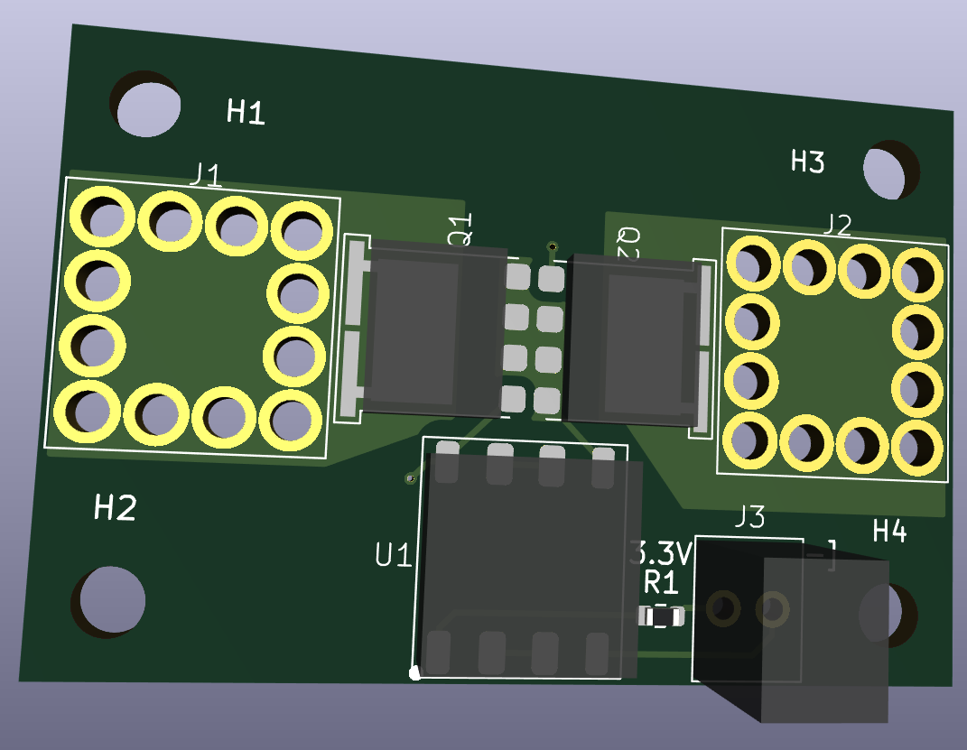
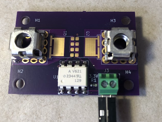
- April 7, 2024 - Built the isolated switch, mosfet and press fit footprints are good!
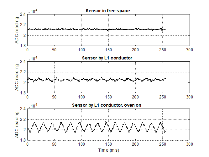
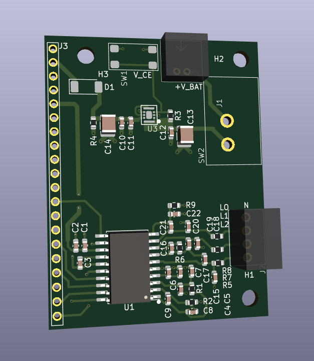
- April 5, 2024 - Just got my AMC130M03 isolated ADC assembled and tested! Yippee, code is on github
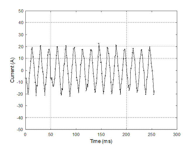
- March 30, 2024 - Just got my hall effect current meter assembled and tested! Yippee, code is on github
Okay, so the photo hints at an apocalypse, but the main inspiration for the project came from the local utility company. The head of the company said we need to be ready for 72 hours without power because weather events are getting stronger.
So, what do I need? A super car that can be a generator, charge from AC or the sun. Yes, that is a Camry Hybrid. The electric motor on the Camry Hybrid is pretty good (>100 HP, Drive.ca Review). I just need a bit more range, plug in charging, DC/AC output for powering my home, and some solar panels. Then, the Camry will be awesome!!!
I looked into getting a generator, but they are bulky, and only roll on silly carts. What if I could drive to the gas station in my generator? Turns out, people already thought of this, and why it is not a standard feature on all hybrids is beyond me.
Not necessarily an endorsement, but please see Youtube Generator Example. I think the top rated comment says it all:
"Having found this YouTube video several months ago, I took it as a weekend project and made everything according to Frank's specifications. (Mine is a 2013 Prius) Everything worked fine, and I put it away -- ready for an emergency or power outage.
Little did I know then how much would I use it, and how hard would it be put to a test. I live in San Juan, Puerto Rico. My diesel generator died on me during hurricane Irma. A few days later, hurricane Maria knocked down 100% of the island's power grid. Close to two months later, 80% are still in the dark (me included). Until I got my generator replaced, during a period of FIVE WEEKS I powered my fridge, several lights, electric fans, my PC, and chargers for several gadgets all with my Prius.
Thank you Frank!! @edgardomunoz6611 6 years ago"
So begins my search to first understand the hybrid setup, define the goals, and then work on the glow up!
What is the state of the world
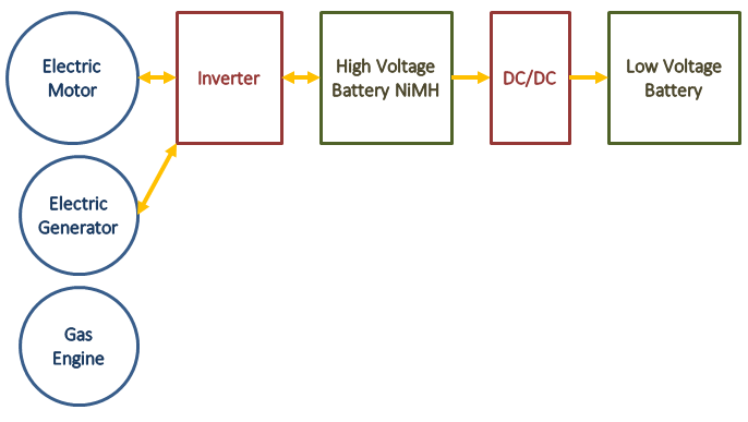
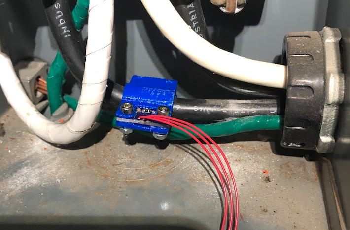
This is my understanding of the blocks. You have a gas engine (duh), an electric generator capable of about 8 kW output, an electric motor capable of about 30 kW electrical input, and a high voltage battery pack that can go up to about 308 V, measured to have a capacity of 6 Ah, or about 2 kWh.
What do I want?
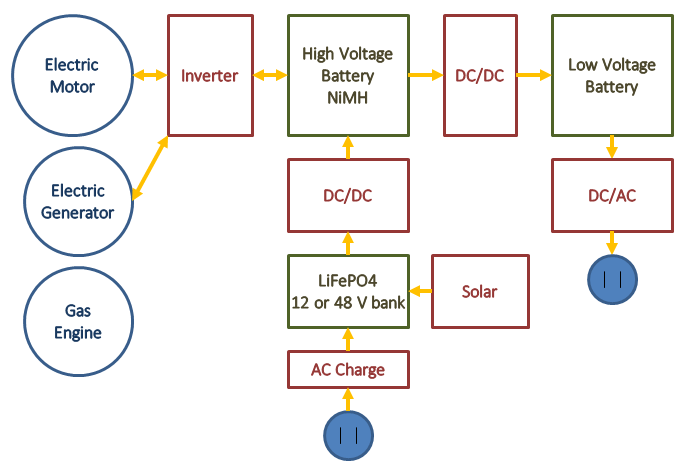
I would like to add about 4.8 kWh of LiFePO4 batteries to increase the electric only range, enough for me, and not to break the budget. I would like an AC charger on board so I can charge with 120 V.
I would like to add a simple DC/AC converter, and apparently, the best place is to connect it to the regular 12V battery, since the car will always monitor this battery and top up as needed.
Lastly, I would like to plaster on some solar panels to the hood, roof, and trunk to get a few kilometers per day.
What are my current goals for this project?
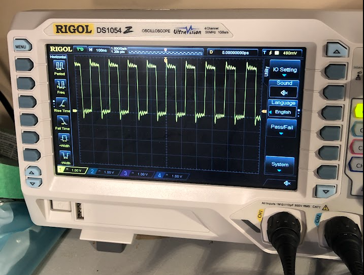
- Cheaply measure the voltage and current for the existing battery pack
- Design my own circuits for this
- DC-AC inverter, either off of the 12V pack (a-la-youtube video), or off of the ~300 V pack
- Off-the-shelf parts
- Add 4, 12V 100 Ah LiFePO4, to increase the range
- This will require a battery holder, and DC-DC converter to be able to help charge the main pack
- I think this will be a custom design
- I think I'll probably use Renogy batteries - replaced easily and quickly, to keep costs down and keep it simple
- Will need cooling for discharge, and possibly for charging...
- Home charger for the LiFePO4 to be able to plug in at home...
- Solar panels on the car to charge the LiFePO4 batteries and provide extra range


 Lithium ION
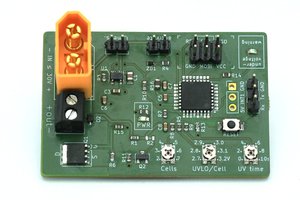
 Jan
Jan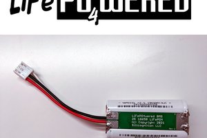
 Patrick Van Oosterwijck
 jbb
jbb