 xykobas3rd
-
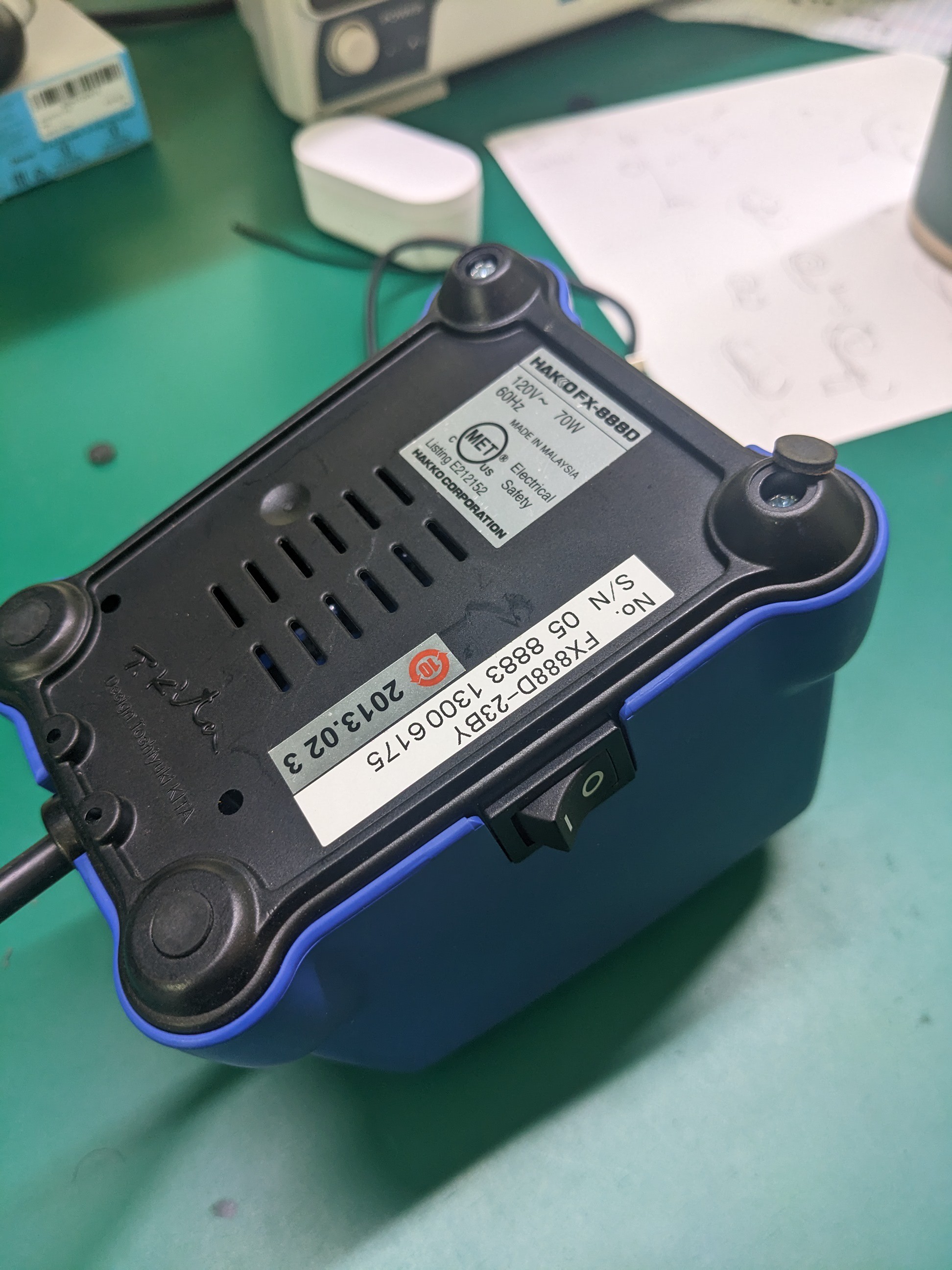
1The base
![]()
Turn the base upside down
Remove the rubber feet to expose the screws
Unscrew four corners
-
2Step 2
![]()
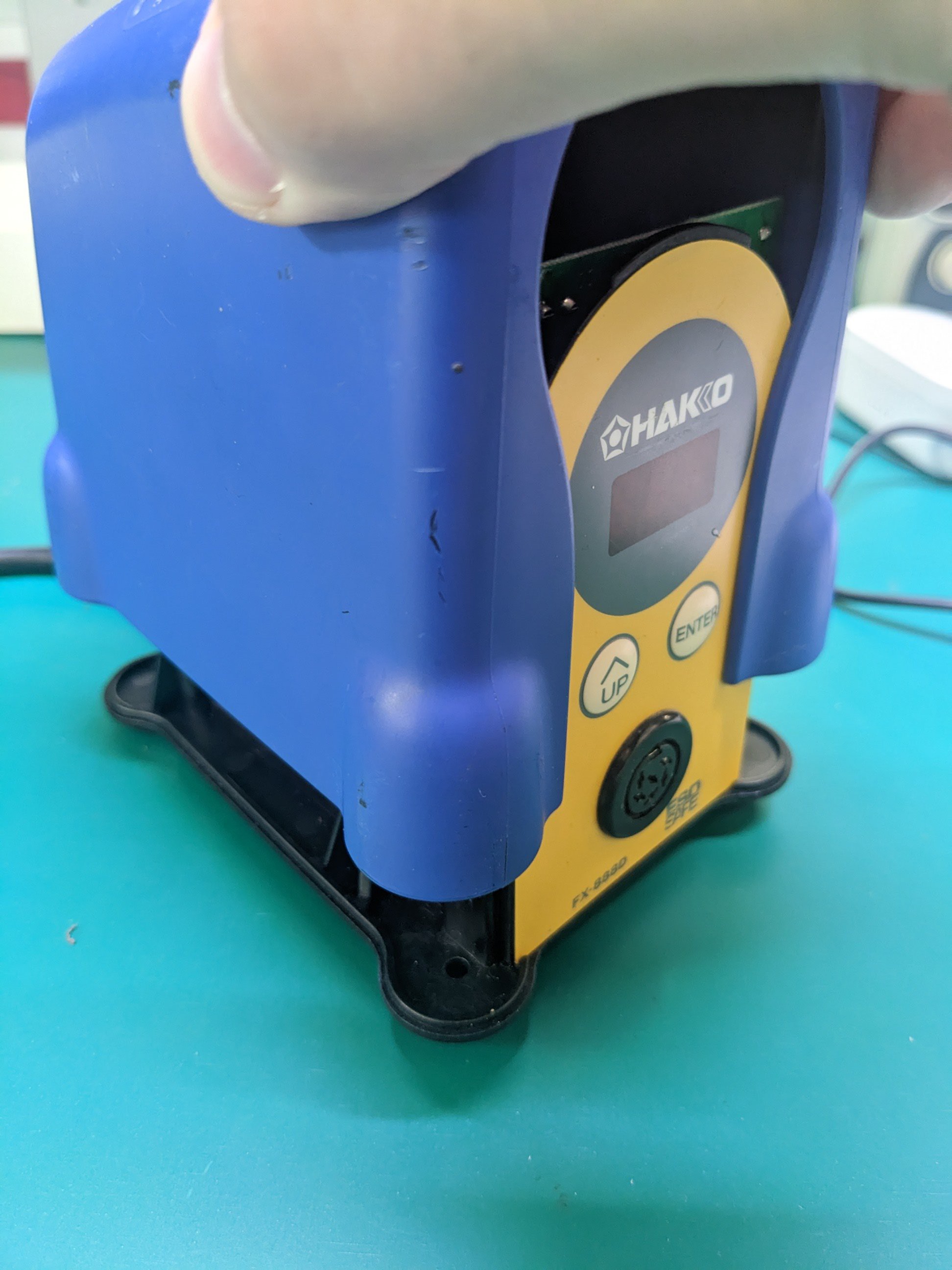
Turn the unit right side up
Pull the blue case up and off
-
3Step 3
![]()
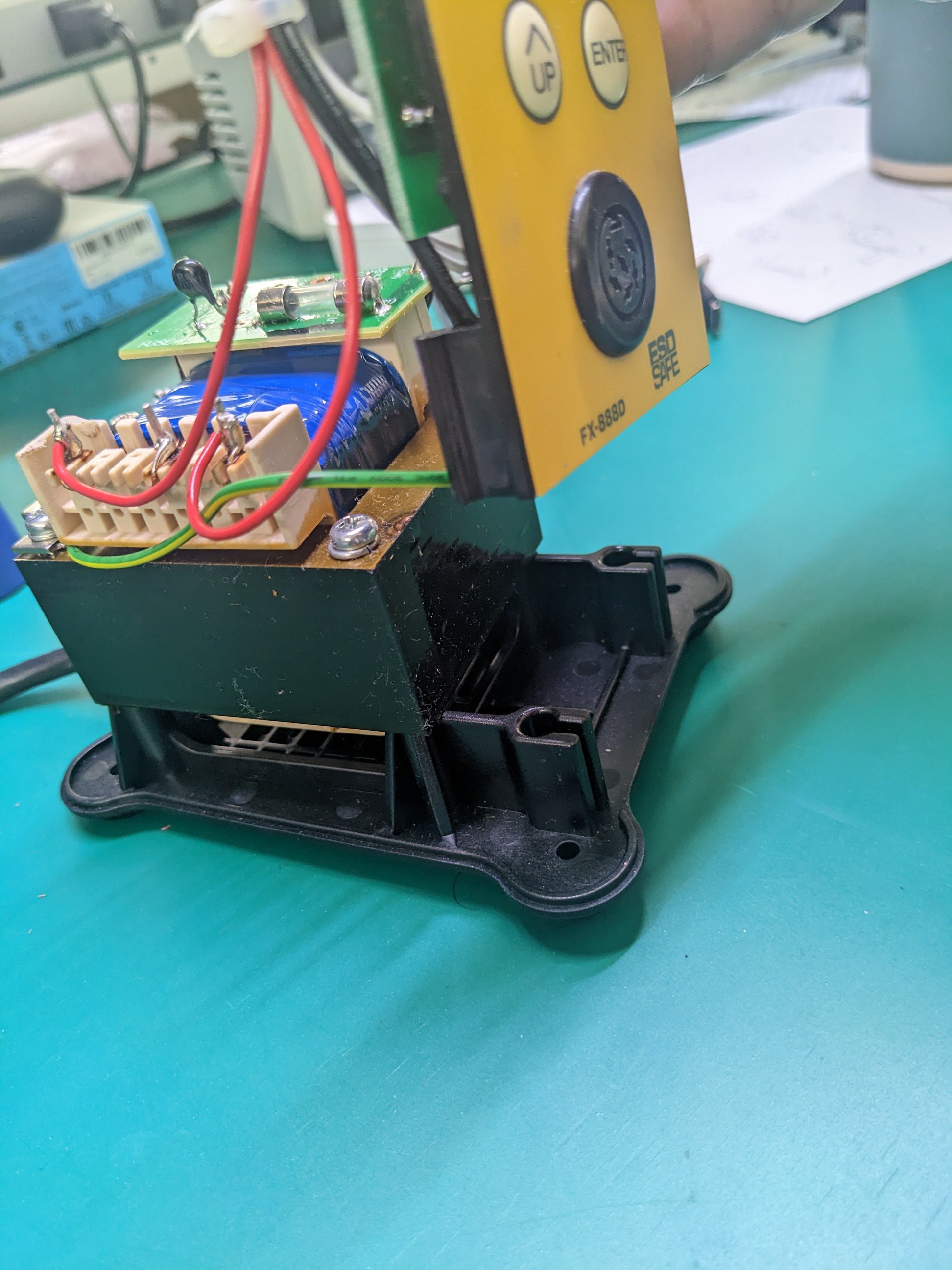
Pull the yellow face plate up and off
Lay it face down next to the base to access the inside of the connector
-
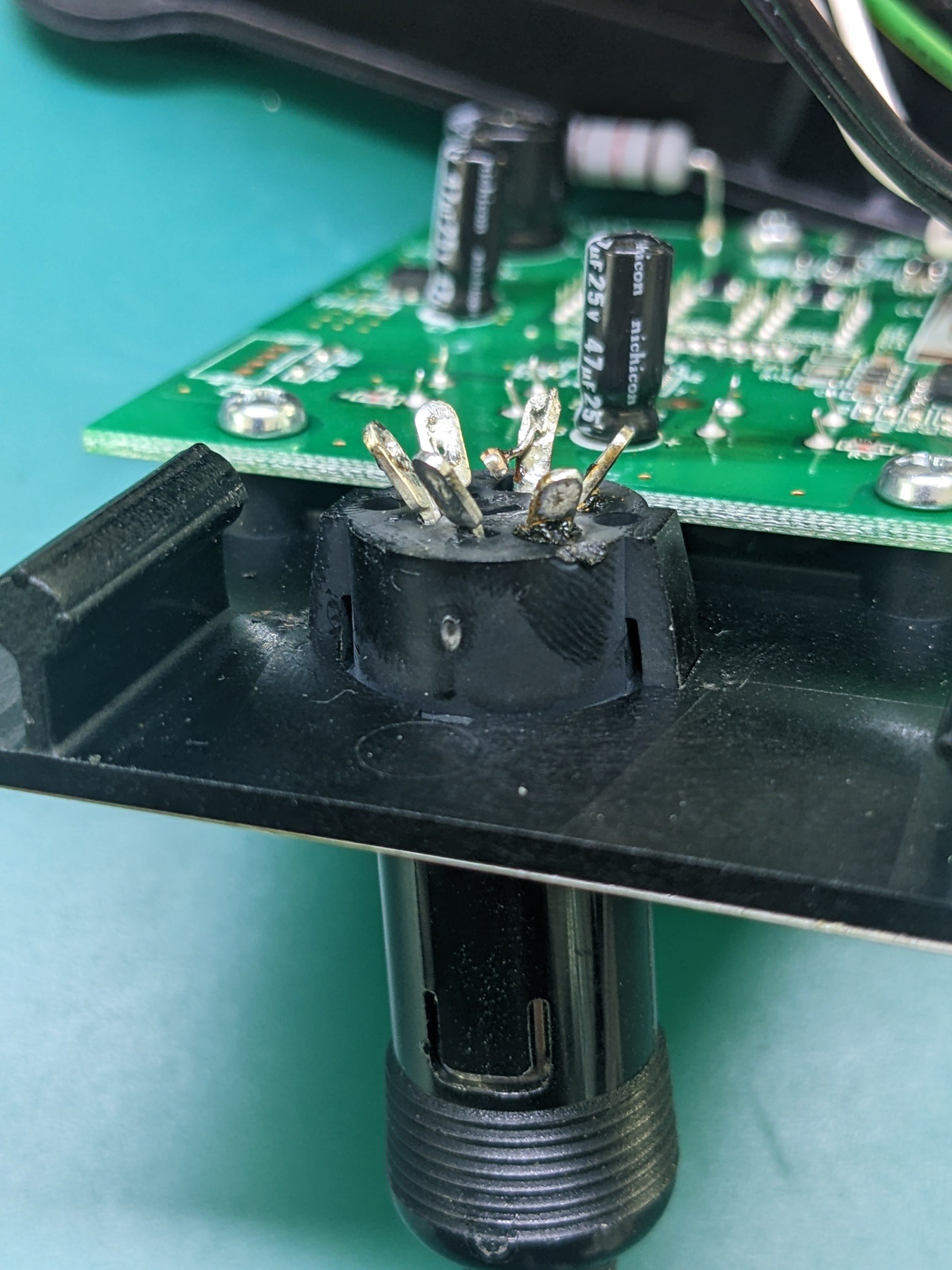
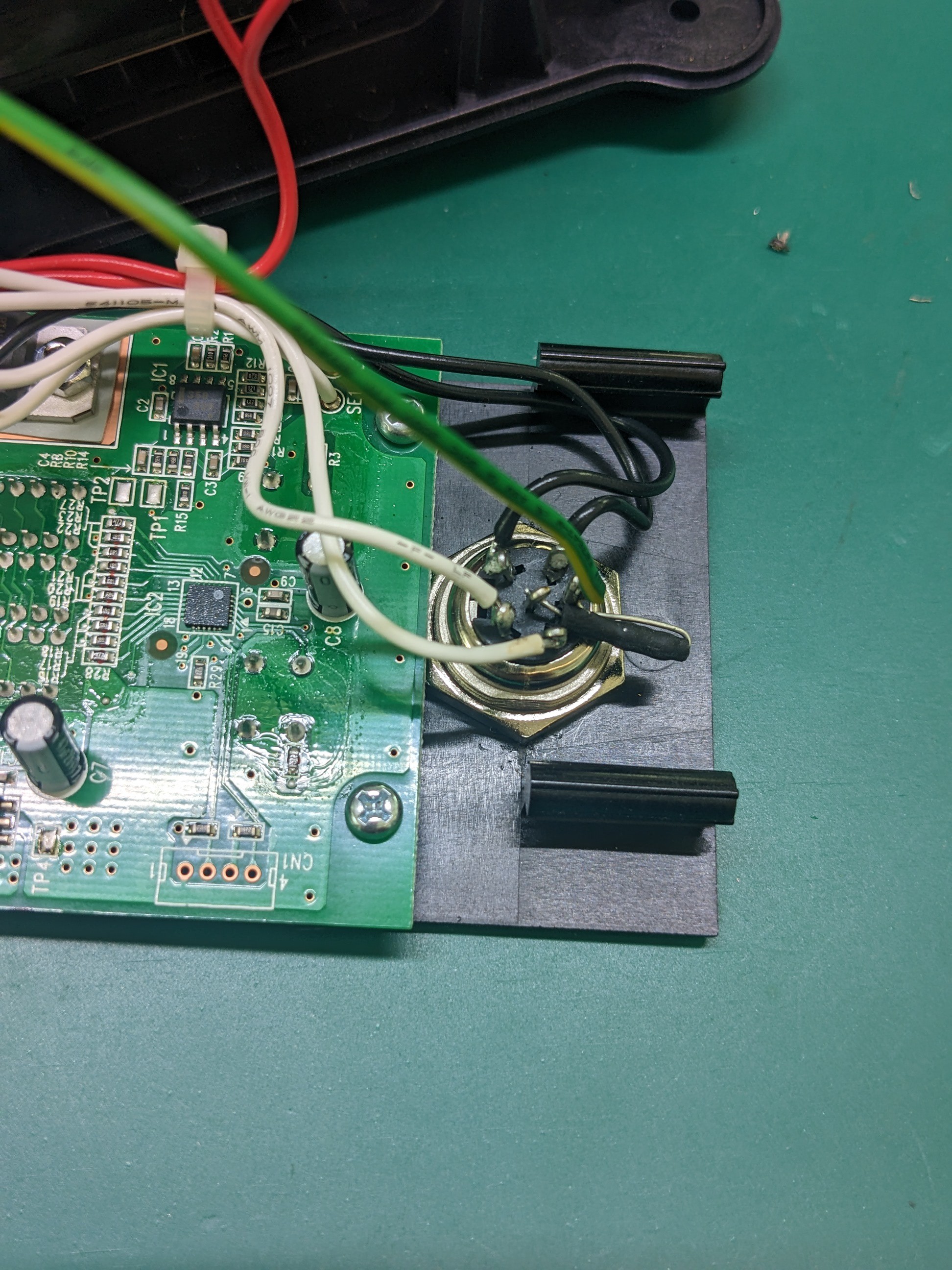
4Step 4
![]()
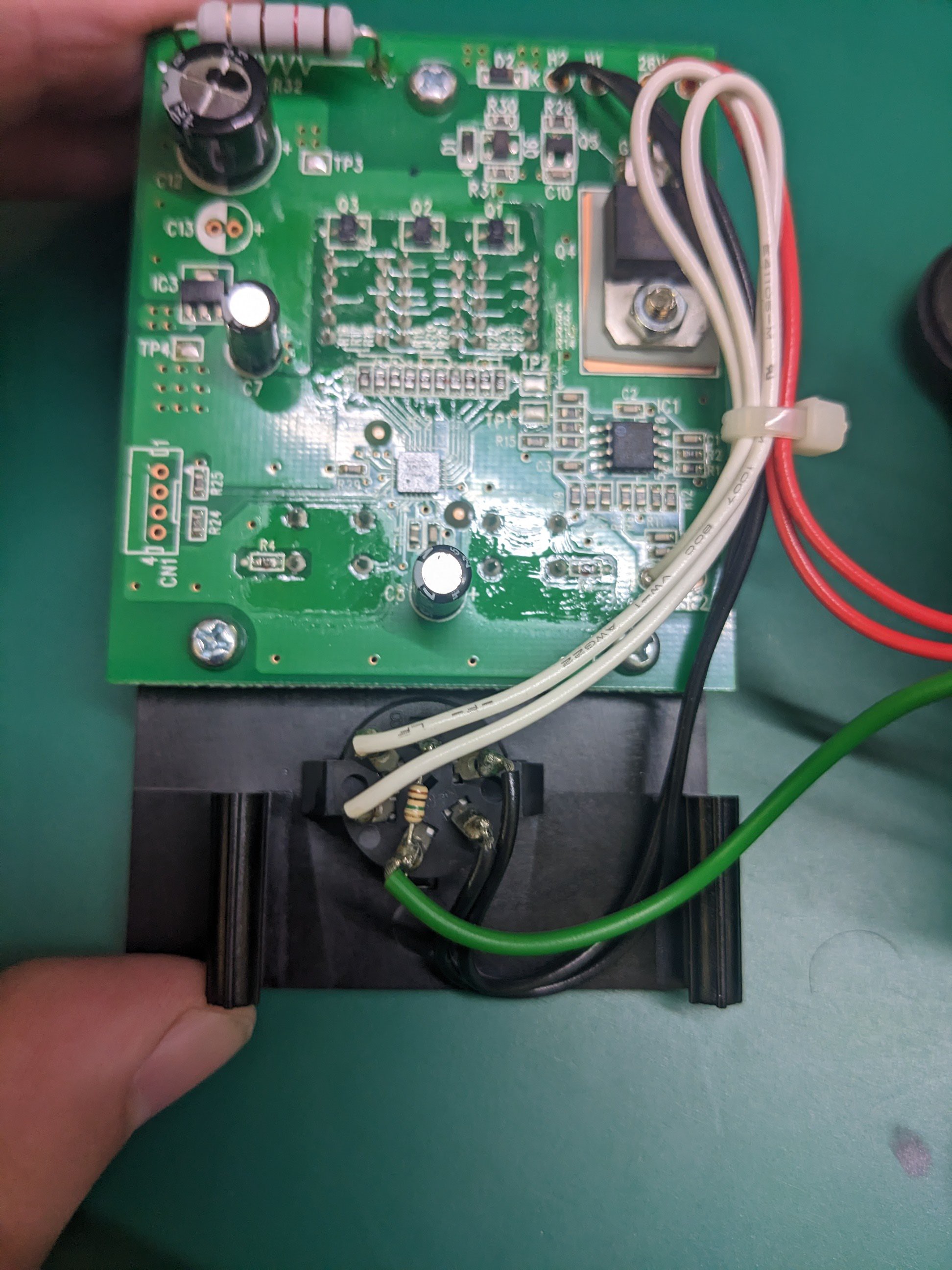
Note the wire colors before de-soldering
White pair on the left
Black pair on the right
Green on the bottom
Bridge the Bottom and Top (Shield?) with a 1M resistor
-
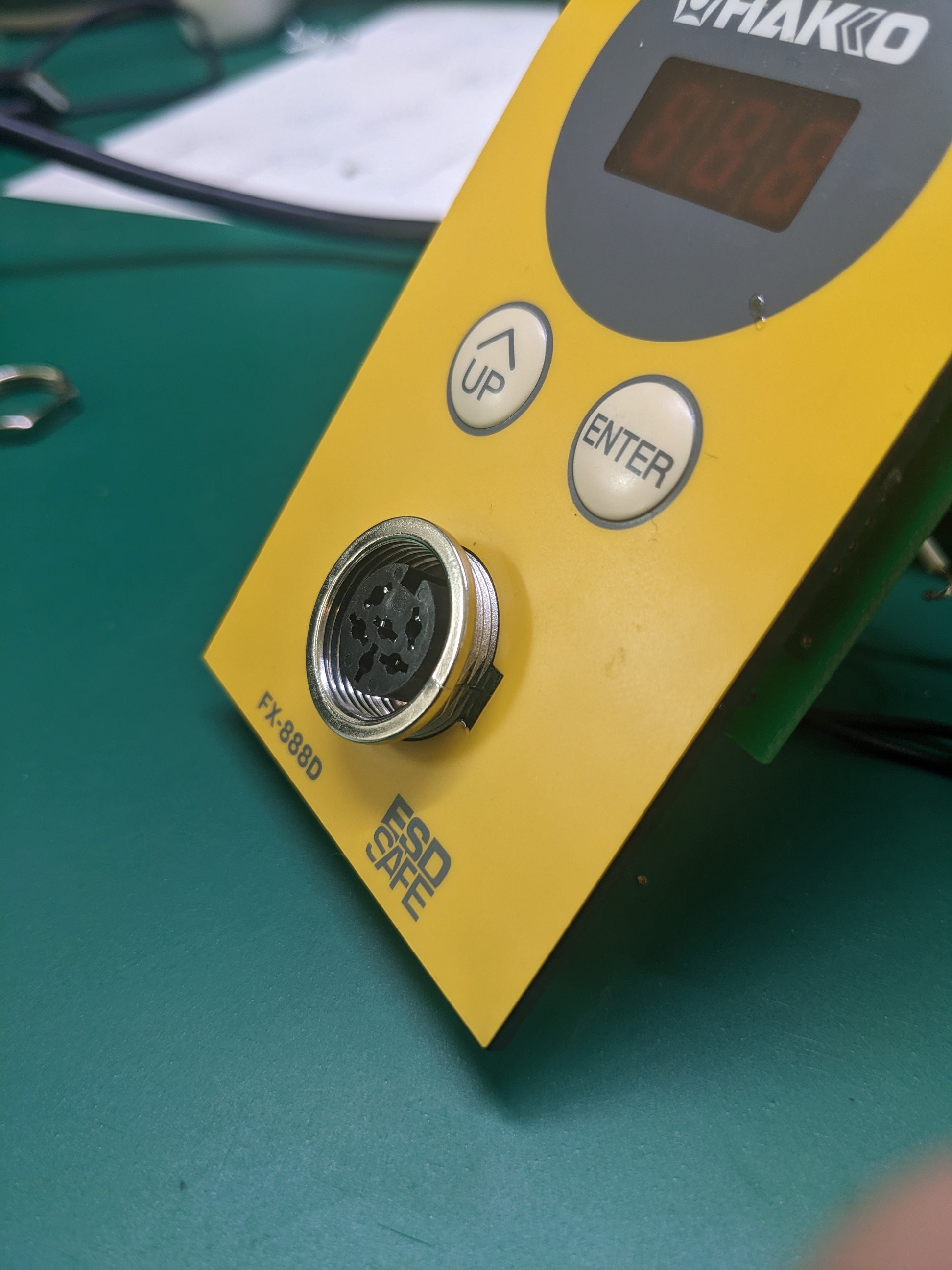
5Step 5
![]()
To remove the connector:
Plug in the soldering iron cable
Use pliers to squeeze the tabs
Wiggle from the tab side and pull gently from the cable side
-
6Step 6
![]()
Push in the new connector
-
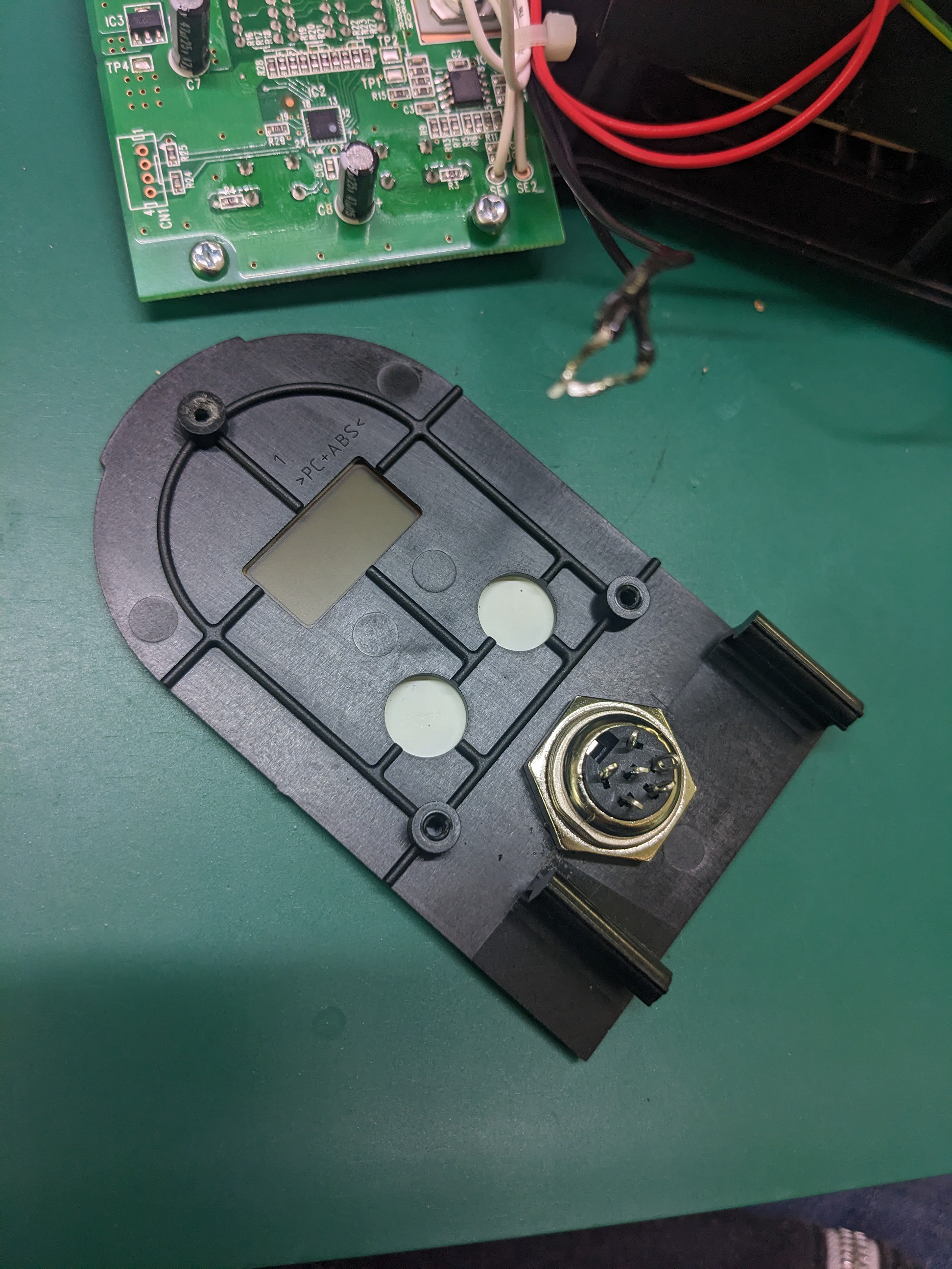
7Step 7
![]()
Unscrew the PCB
Screw on the connector's locking nut
Replace the PCB
-
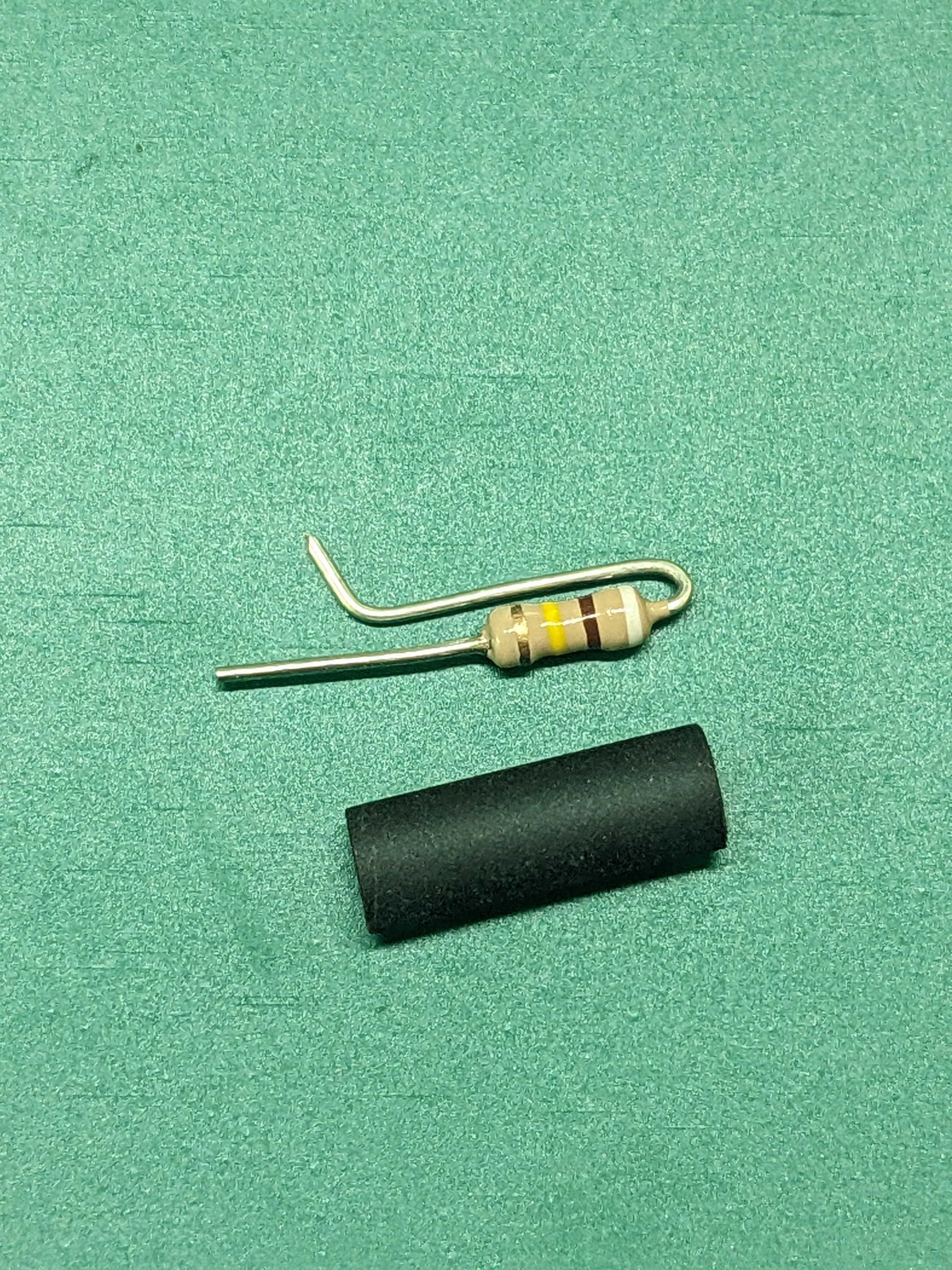
8Step 8
![]()
Heat-shrink over the 1M resistor (910k...close enough)
-
9Step 9
![]()
Re-solder the connections onto their corresponding pins
(This is when I realized... the shield of this connector does not have a dedicated pin. So in this configuration the resistor is rendered useless. One day I'll move the resistor from the center pin to the connector casing directly.....maybe)
-
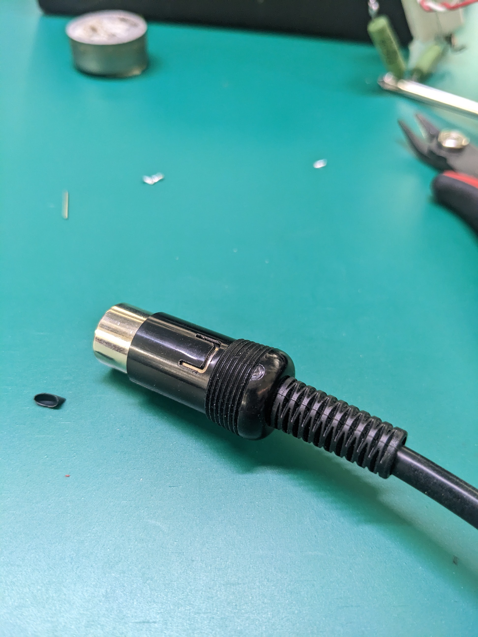
10On to the cable...
![]()
Use a small flat screwdriver to pry up the black tab
Pull the black sleeve towards the cable to reveal the innards
Replacing Hakko FX-888D connector
The pins on the panel mount connector lose their springy-ness over time causing an intermittent connection
Discussions
Become a Hackaday.io Member
Create an account to leave a comment. Already have an account? Log In.