This DIY drone is small in size and can be built using easily available components such as ESP32 modules, MPU6050 IMU, coreless motors, and plastic propellers.
Features of our DIY WiFi-Controlled Drone
- WiFi controlled: This can be controlled using a smartphone.
- MPU6050 IMU for stability control.
- All-in-one PCB: Doesn’t need any 3D printed parts or such.
- Easily upgradable: Additional features such as position hold or height hold can be added using external modules.
- Small size and lightweight.
- Built-in battery charger.
- Built-in USB interface for programming and debugging.
- Android and IOS apps.
- Open source
Approximate Build Cost
Here is the approximate build cost for the drone. Keep in mind that the costs provided here are not exact and may vary depending on the vendor. The prices are calculated based on the cheapest options available from reputed vendors, with only the bare minimum number of components as the minimum MOQ.
| Capacitor, Resistors, diodes & MISC | ₹ 100.00 |
| MOSFETS | ₹ 40.00 |
| ESP32 | ₹ 240.00 |
| TP4056 | ₹ 17.50 |
| MPU6050 | ₹ 140.00 |
| CP2102 | ₹ 200.00 |
| 720 Motors + 55mm propellers | ₹ 266.00 |
| PCB | ₹ 100.00 |
| Total | ₹ 1093.50 |
DIY WiFi-Controlled Drone Complete Circuit Diagram
The complete circuit diagram for the DIY WiFi Controlled Drone is shown below.
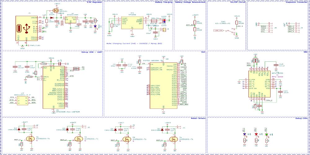
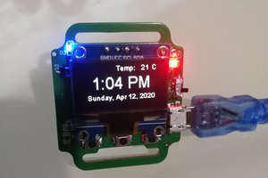
A Type C USB port serves both charging and programming functions. Its power path controller, utilizing a P-Channel MOSFET U2 and diode D1, allows seamless switching between USB power and battery power, with voltage regulation ensured by the MIC5219 3.3V LDO from Microchip. A slide switch activates the thermal camera while a TP4056 charge controller manages battery charging. Voltage sensing is facilitated by a classic voltage divider circuit. Moving to the programming section, an ESP32 SoC, CP2102 USB to UART controller, and MPU6050 PMU chip form the core. The CP2102, coupled with a dual MOSFET, simplifies ESP32 reset functionality, while standard circuitry surrounds the ESP32. The MPU6050 PMU aids in flight stabilization and motion control, interfaced with the ESP32 via GPIO pins. Finally, motor driver circuits employ SI2302 N-Channel MOSFETs for motor control, supplemented with protective diodes and resistors. Debugging LEDs, including a blue LED for calibration, a green LED for connection detection, and a red LED for low battery indication, enhance operational monitoring alongside power and charging indicators.
You can find more detailed explanations and other details on the project page Let's Build a Low-Cost Drone using ESP32.
PCB for DIY WiFi-Controlled Drone
For this project, we have decided to make a custom PCB. This will ensure that the final product is as compact as possible as well as easy to assemble and use. We have also designed the PCB in a way that the feet for the drone are also included in the PCB and Can be easily broken away from the main PCB. Here are the top and bottom layers of the PCB.

Here is the PCB.

And here is the fully assembled drone.

Propeller Direction
Install A and B propellers according to the figure below. During the power-on self-test, check if the propellers spin properly and are spinning in the correct direction.

Firmware for the DIY WiFi-Controlled Drone
The firmware from our DIY drone is based on the ESP-drone firmware from Espressif. The code is written with ESP-IDF, and the version that is used to compile this code is ESP-IDF 4.4.5. Follow the following link to install and configure ESP32 IDF version 4.4.5. You can either build the firmware from scratch using the source provided at the Github repo below or you can just flash the binary file provided within the same repo if you don’t want the hassle. Make sure to use the source code provided within the below GitHub, because there are many modifications on the Espressif’s code to suit our...
Read more »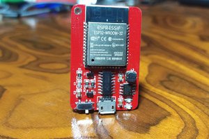
 SAYANTAN PAL
 CarbonCycle