The first would-be module and limited desk space are what gave me the idea for the whole thing.
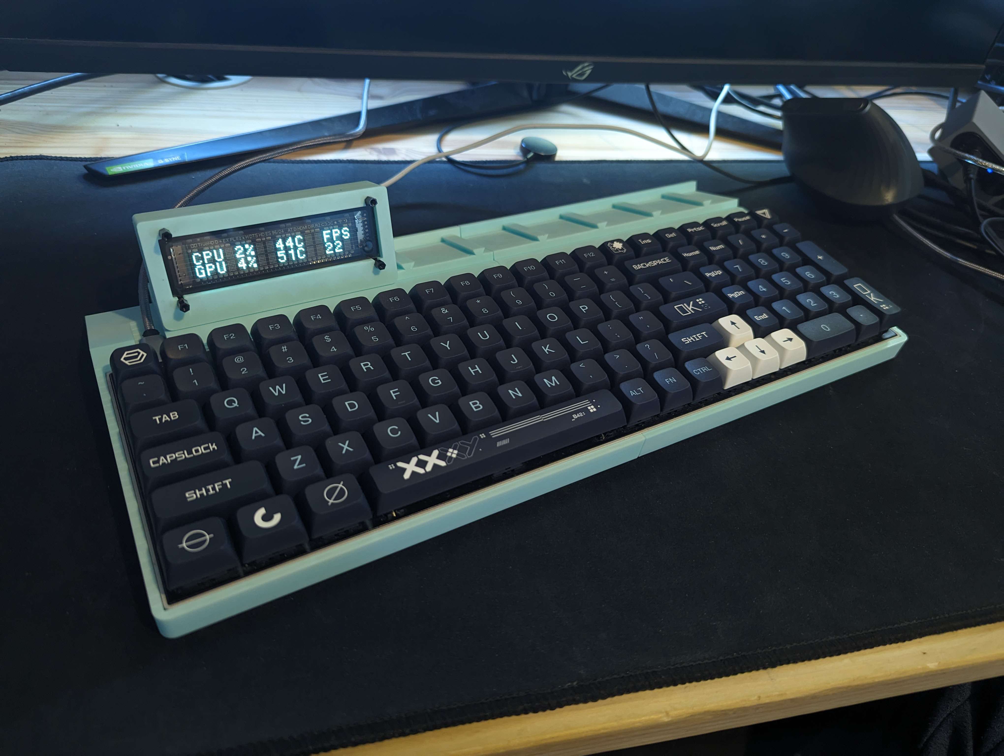
I had a VFD that I bought off of AliExpress (which talks to AIDA64 and can show the usual PC info), but no way to properly keep it on my desk (it connects via a micro USB cable, simple enough, but it had no enclosure of any sort).
I thought to design and print a simple enclosure for it, but it would be yet another device floating about on my desk. Instead, I (somehow) had the idea to attach it to my keyboard.
I designed and printed a case that my keyboard drops into, and a basic rail system with indents that the VFD enclosure snaps onto via thin tabs with hemispheres on them.
The module itself is not much more than a rectangular tube with a few holes that the VFD mounts to with standoffs, but that is all it needed to be (that module is still the same as the first prototype. Something something "it just works").
The keyboard being used (and still is) here is a Tab 90M by Vortex.
This board was already my daily driver, and the fact that the case has no bezel (low profile bezel? low profile case?) means it just drops into the frame without needing to remove its case. In the future I may remove it from the case anyway to reduce the thickness of the front and sides, but for now it's staying as is.
Unfortunately, they don't seem to sell them anymore. That said, most other keyboards of a similar size with a thin/no bezel case should work with simple adjustments to the model.
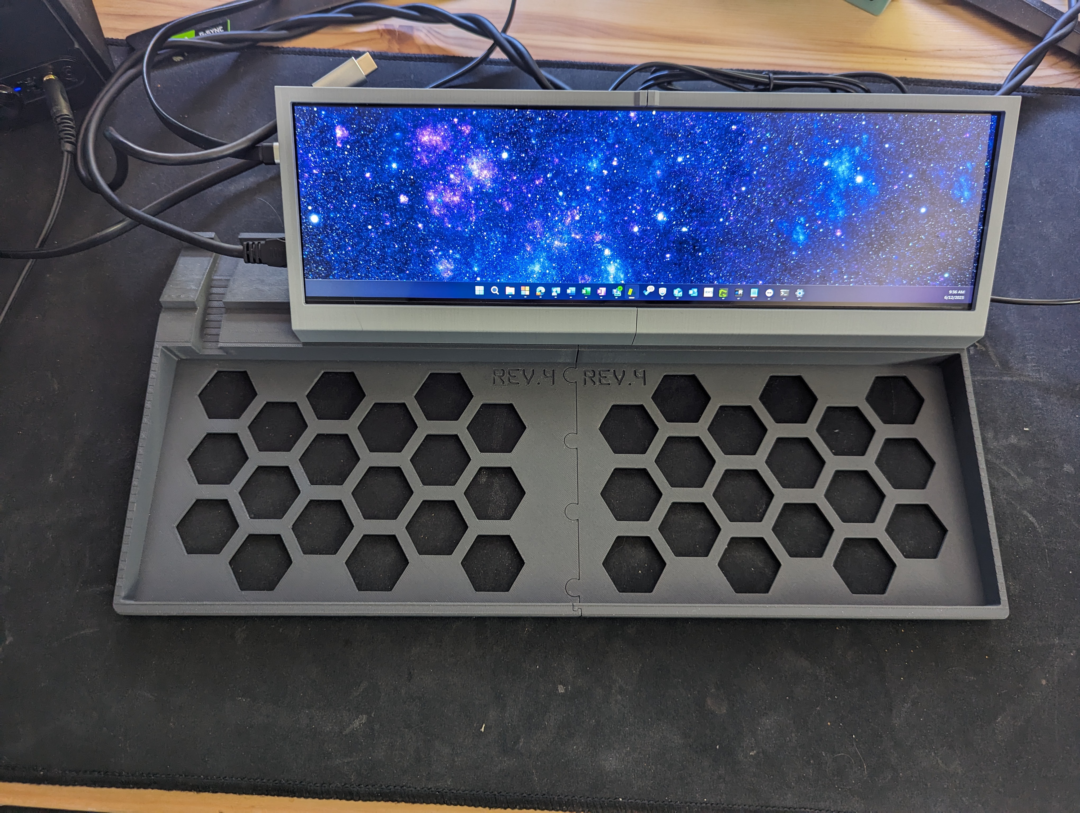
From there, I was inspired by those notebooks with an LCD attached to the top of the palm rest.
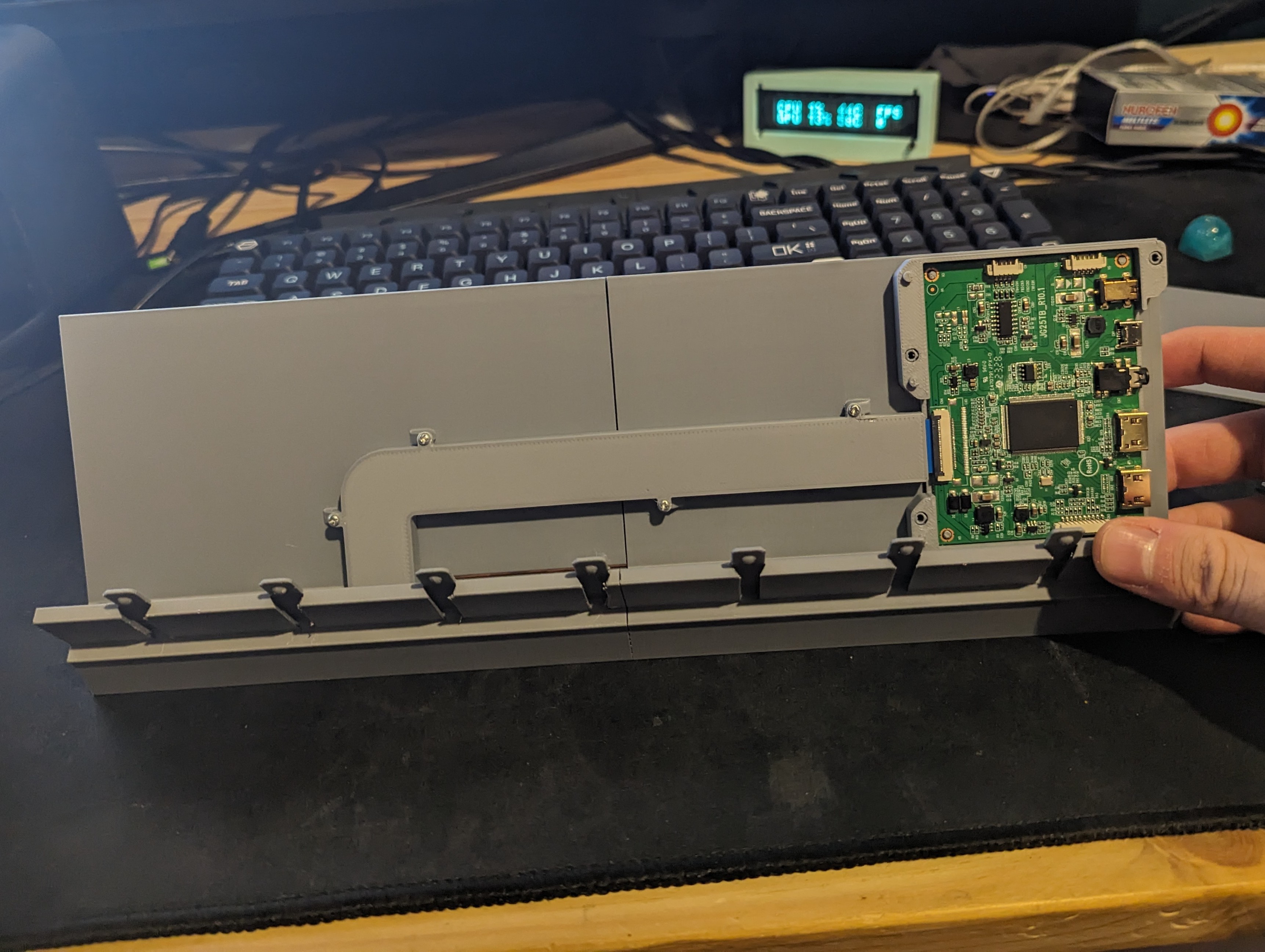
I found a panel LCD on Amazon, and came up with a way to attach it to the frame. It went through several iterations, but this is where it is currently (aside from a few slight changes).
Beneath the cable channel is the LCD flex cable. The purpose of making the driver board separate to the LCD enclosure itself is, 1. ease of printing, and 2. the ability to modify one without also reprinting the other.
Unfortunately, the LCD is wide enough that the VFD module can't be used at the same time, so these two modules can't be in the same setup.
That said, there aren't going to be many that can be used with it. Currently I only have two others, one of which is a 'companion' module.
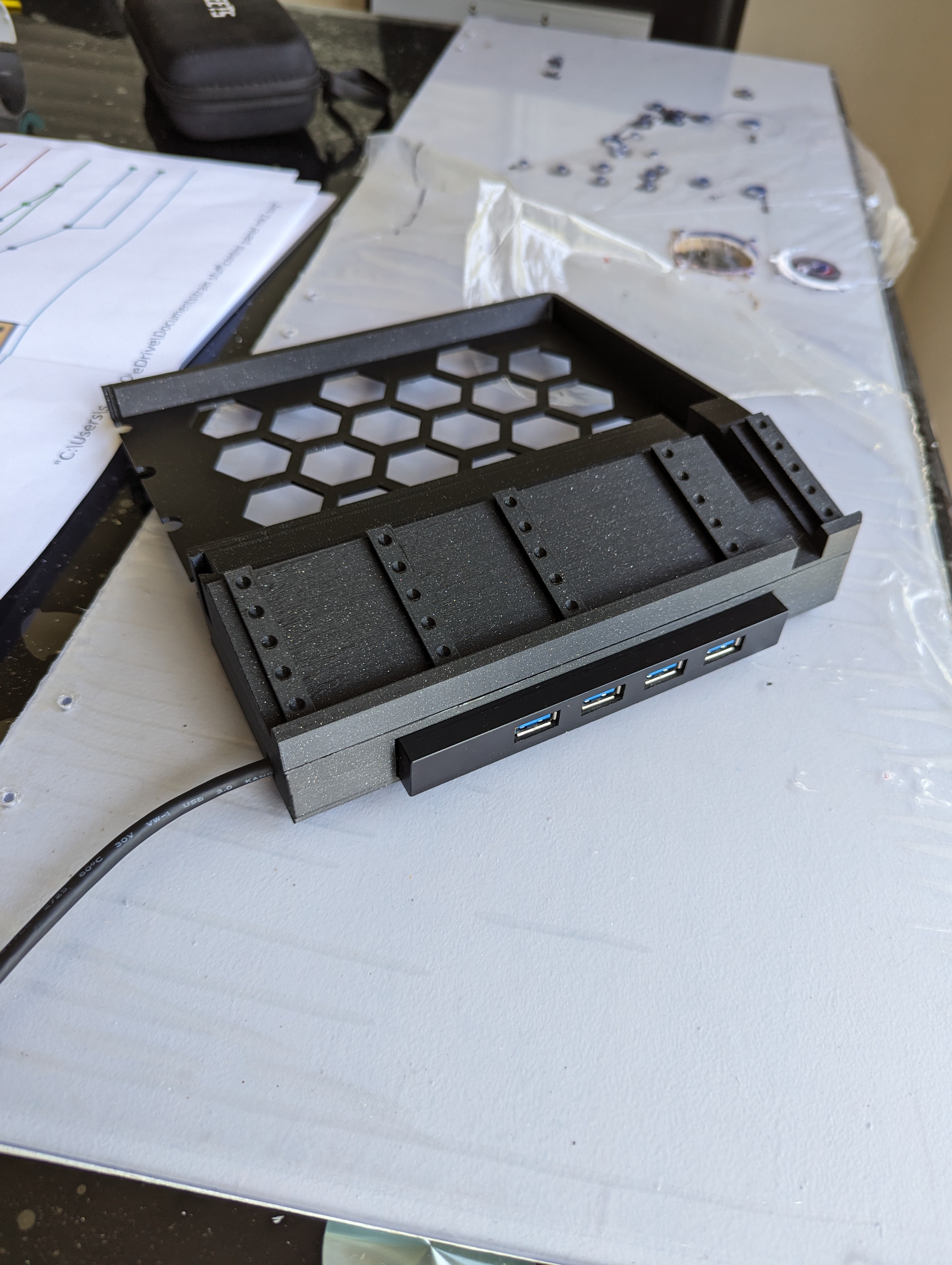
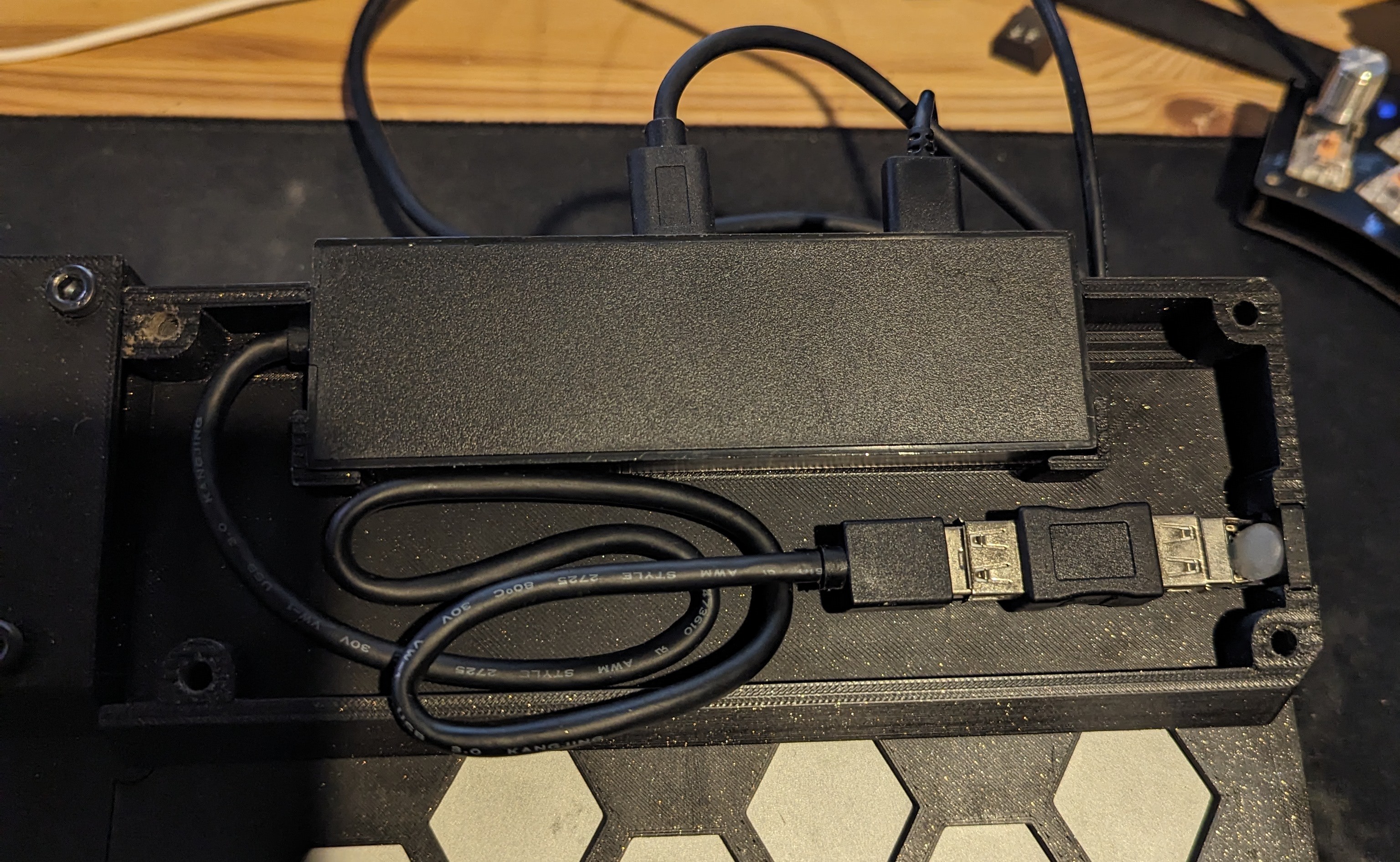
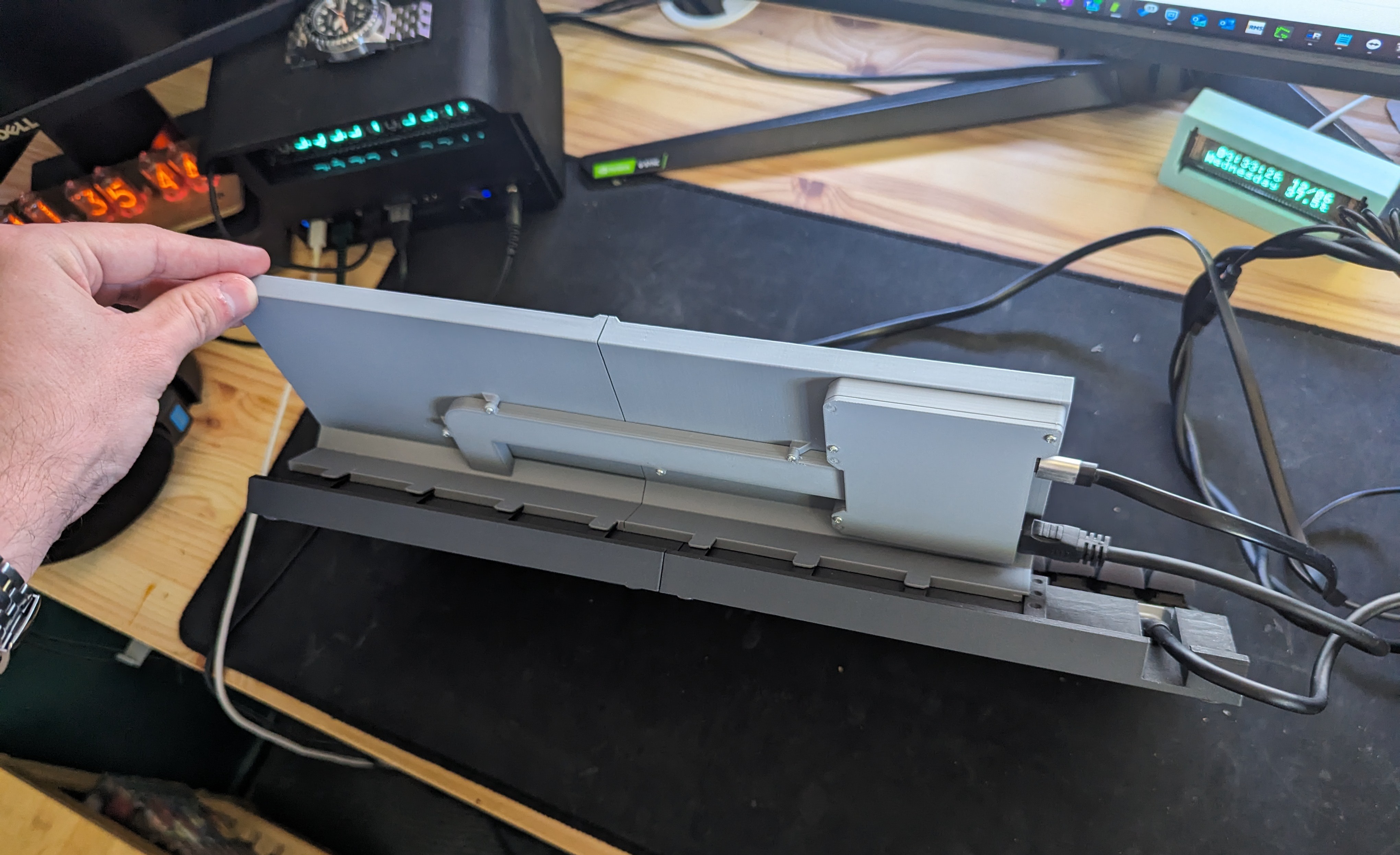
I later decided to implement a USB hub into the frame. This meant adding a pair of compartments (one for each half) to the underside of the frame.
It could be wired in one of two configurations:
The first was a fully wireless setup, using a battery in the other half, a HDMI transceiver, and a Bluetooth module. In this mode, the hub was only for power supply to the devices (the Bluetooth module, the LCD and the HDMI transceiver).
This was abandoned due to horrible battery efficiency, and the cheap HDMI transceiver not properly scaling for the long, short LCD.
I'll include the STLs anyway since it did """technically""" work for a few hours per charge.
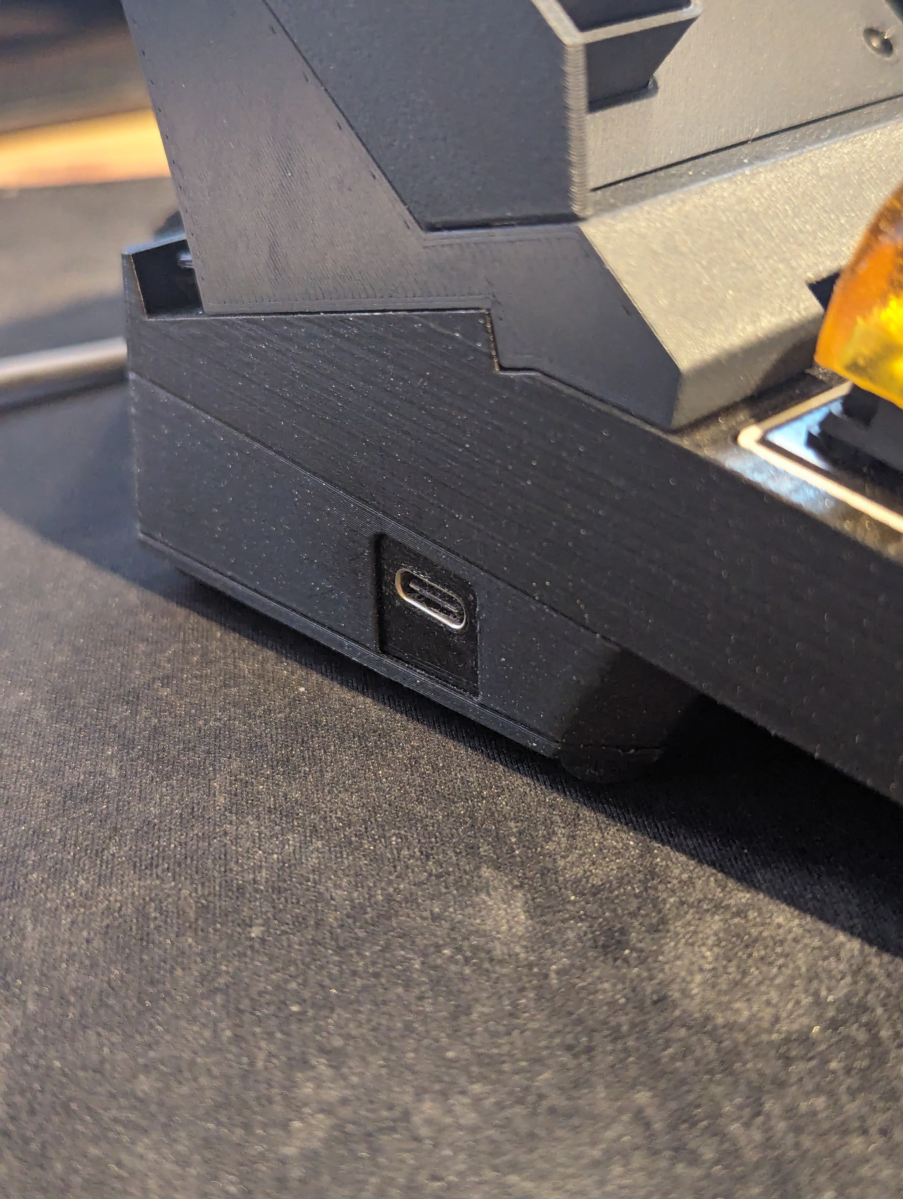
The second (and current) setup simply uses the integrated hub and does away with the battery entirely.
A chain of internal USB adapters (which will be replaced with the hub cable soldered to the female UCB C later on) gives it a USB C connector that links to the hub internally. This means that only one USB C cable goes to the PC like a normal keyboard.
That is pretty much all of the major steps along the way so far. There has certainly been a lot more, but nothing worth making a note of.
Recently I made the companion module for the LCD I mentioned earlier; a cable run for the power and HDMI cords as well as a power switch that connects to my PC's motherboard, which I will document in a new post as it is very recent.
Discussions
Become a Hackaday.io Member
Create an account to leave a comment. Already have an account? Log In.