 awkward intelligence
Inspiration
When con holders plan to throw a conference, the biggest hurdles seem to be money and know-how. So this badge was an attempt to simplify that process.
Anyone who has a foundation in photoshop or vector art can create an art-based PCB badge if they follow the Inkscape method. However when making art that also does things with electricity, skills are needed that not everyone has. The thought was to create a “light up” backing badge that anyone could print an artistic cover for. Provided that design fit the 50x80mm footprint for the 3.2mm(M3) mounting holes to attach the top/cover badge.
Yes. This badge was designed so one could make their own artwork to go on top.
An attiny LED matrix seemed like a fun, achievable project to include on a badge. But it does take a lot of time to make. Which is why we also included a fun rgb Blinky feature on the same circuit.
The result is that there is no “OFF” switch for the badge, only a selection of 2 different circuits. If the attiny Matrix is non-populated then it will still send current through the badge even when it is not making light. So please be careful about drinks and other things that can short out your badge.
For the purposes of Hackspacecon 2024, we will utilize the RBG party mode for the conference and those that desire to create the matrix will have the ability to do so. Quantity of parts are however limited.
Design
The LED matrix circuit is a redesign of my TV3Y3 badge with an onboard touch button instead of a physical button. It is a little sensitive but remember that sensitivity is based on humidity, meaning environment plays a big role in how the button works. You could use a higher voltage resistor or simply remove the button functionality in the code.
PUT YOUR BATTERIES IN BACKWARDS!!!
When ordering parts from China it is not uncommon to find schematics reversed, wrong sizes, it can honestly be a crapshoot sometimes. So if the battery holder is backwards, sometimes you just consider yourself lucky that that’s the only issue. Because the design still works, as long as you plug the batteries in backwards.
Mounting holes
In retrospect, making a kicad footprint for the mounting holes is what I should have done. However, when I was designing this, I wasn’t sure if we would get a second chance. That the prototype run might actually be the full order, and that everything had to fit right from the first run.
In order to do this, I built the top art badge first, laid out the mounting hole positions and then rebuilt the backing badge around those mounting holes.
The reason I touch on this is because this badge was designed to be used as a backing for other badges, and in order to align the mounting holes properly, you need to place the M3 mounting holes(3.2mm) evenly on the corners of a 50mm X 80mm rectangle. You’ll notice the finale size of the backing badge is 60mm X 90mm.
The Circuit
The Lights should go on the side with an “A” in the corner. The battery holder, switch, and Chip/socket should go on the opposite side. Resistors can go on any side you want. All of the LED footprints are accurate (for the general admission).
J1-4 are the matrix pins. You should use a resistor(100ohm) to connect them to the desired pin of your attiny. I didn’t specify a attiny pin for each row because of variation in code, pins and models. RGB Party mode is the easier, default circuit.
Assembly
Parts:
12 LEDs
4 100 Ohm resistors
1M resistor for touch button.
1 8 pin socket
1 attiny chip.
STEPS:
1. Solder on the socket.
2. You will need to wire(bridge) the vcc and gnd to pins 8 and 4, respectively. This can be done with a little wire or a glob of solder.
(I recommend bending the pins towards the pads to be wired)
3. Connect 100 ohm resistors between:
J4 and pin 2
J3 and pin 3
J1 and pin 7
J2 and pin 5
4. For touch functionality...
Read more »

 facelessloser
 Steph
Steph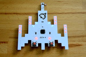
 Mike Szczys