Silícios Lab
Introduction
Do you want an electronic board for activating loads via WiFi that is safe against surges in the electrical network and with high immunity to noise to avoid failures/locks in your ESP8266 circuit?
Problems with code locking, lack of protection against electrical surges, lack of development of a secure electronic board are just a few points that users do not know how to develop. This causes several problems in the process of creating professional projects and prevents the circuit from working efficiently to drive loads in the field of application.
To solve these and other problems, we developed an electronic project for the board below and implemented the following circuits:
- Power supply from the electrical network,
- Short circuit and overvoltage protection circuit,
- Power supply isolation circuit,
- Circuit with optocoupler for driving relays,
- And among other blocks.
Take advantage and download all the manufacturing files, list of materials and component place list for assembling the printed circuit board on PCBWay.
In this article you will learn how to use this printed circuit board and develop an application to activate the relay from a web page.
The Printed Circuit Board for Relay Drive with ESP8266
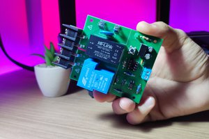
Circuits with relays are frequently requested when it is necessary to activate higher power loads that are connected to the electrical network. As already mentioned, the big problem is that users do not know how to assemble the ideal circuit and this causes serious problems in the drive system.
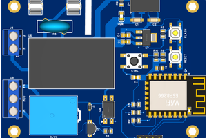
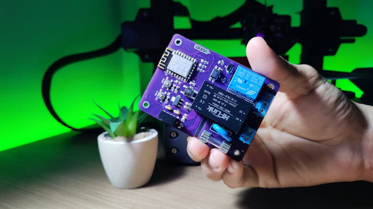
Below we have the structure of the developed electronic board and from now on you will learn how to create an application to control any load from your computer or cell phone.

This electronic board must be powered by the electrical network and can be supplied with voltages between 127VAC and 220VAC. The input circuit consists of the varistor, fuse and Hilink source, as shown in the figure below.

From the Hilink AC-DC converter, we have an output voltage of 5VDC to power the direct current circuit. As you can see, we have a relay and, when activated, it is common to generate electromagnetic interference and cause the microcontroller chip to reset or lock. How to avoid this problem and ensure the safe operation of the CHIP?
Circuit for isolation of power supplies
The source isolation circuit is essential to completely isolate two parts of a circuit. Our objective in this project was to create an isolated power supply to power just the ESP8266 and another source to power the rest of the circuit. For this, we use the B0505S device.

The B0505S is an isolated DC-DC converter device. It receives the 5V input voltage that comes from the Hilink source and then provides an isolated DC voltage at its output with a value of 5V. Its maximum current supply capacity is 200mA. This current is sufficient to be used in the ESP8266 power circuit.
From this isolation, there will be no direct connection between the ESP8266 circuit and the relay, as there is an optical isolation circuit with the PC817 optocoupler. See the figure below.

This way, there is complete isolation and safety in the relay activation process through the ESP8266. As previously discussed, these circuits provide greater safety for activating loads in the field of application.
Next, we will discuss an application to be embedded in the ESP8266 and activate the relay through a webserver.
Programming to activate the relay via WiFi
The electronic board system consists of a relay to activate the load. To do this, there are 2 ways to activate the relays: you can use a button connected directly to the board or use a webserver with buttons to activate it.
In this application we use a server to allow activation through a web page. See the interface below.

_j3AFbELu1U.jpeg?auto=compress%2Cformat&w=740&h=555&fit=max)
The interface...
Read more »
 kamalkedin123