 atelierlelu
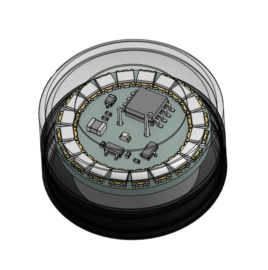
Designing lampion
This writeup documents (in depth) what I have learned and the decisions made during the design and manufacturing process of lampion, a tiny solar harvesting (faint) ever light.
It’s a small cosmetics box containing a LED that turns on at night forever, even when kept indoors as long as there is some natural light during the day.
Disclaimer: things may be wildly incorrect here, so act accordingly (or even better, let me know so we can all learn).
Inspiration
I came across Ted Yapo’s TritiLED project and probably read the project log entries 5 times before I started understanding what I was reading, and then I decided to make my own. I went straight into designing a board using a STM32L0 which is what I had experience with (and in my spare MCUs drawer) and I basically failed - could not reflow solder the thing, or could not program it, not sure.
Then I forgot about it and moved on to other projects more within my reach.
I eventually stumbled upon a remake of Ted’s project using a ATtiny85. At the same time I was exploring ways to harvest indoor light to power super low power projects, and I found Armalamp and other projects from bobricius. I decided to try and combine the two and it looks like I will manage this time.
Requirements
Must haves:
- produces light which is bright enough to easily see at night
- manufacturable
- not too expensive (total costs not more than £10 a pop in a small-ish production run)
- should survive several days in total darkness, and basically forever under realistic natural light conditions
- fits in a 3g cosmetic jar (⌀ 29.5mm, height 16mm)
- I should learn new things in the process, and spend my time/energy on what I enjoy doing
Nice to have:
- no lithium-based battery (because shipping is a pain)
- no over-reliance on a miracle magical part or IC
Oh, and the most important: done is better than perfect. Too easy to never finish hobby projects like this one.
Hardware design
The overall idea is to:
(1) use photodioes to harvest ambient light
(2) charge up some form of energy storage
(3) use that to power a MCU
(4) which generates brief pulses to light up a LED
(5) and use the famous trick of charging an inductor and letting that light up a flyback LED to reach higher light intensity per W than when directly under-powering the LED - read Ted Yapo’s notes if you’re confused here
Microcontroller
The original TritiLED uses a low power PIC, Everled uses a ATtiny85, and I had STM32L0s around so I tried that first. Long story short, I did not manage to make it work. Between soldering it manually (a UFQFPN-20 package - 0.5mm pitch) and having a cheap connector to program/debug it, I never made it work.
Besides, low power modes on ARM are a massive pain to get to work, resume from low power modes was slow, and frankly a fully Cortex-M0+ and 32bit was way overkill for what I needed: a periodic wakeup every ~20ms or so to pulse a high signal for ~1us before going back to sleep. And maybe read the voltage produced by the photodiodes once in a while.
So I went with ATtiny85s I also had lying around and got working. The low power modes and watchdog timer configuration and related interrupt handling are MUCH simpler - the program is about 10 lines of actual code only.
The ATtiny85 is not exactly a low power microcontroller, but it does spend the overwhelming majority of its time asleep, during which it consumes ~4uA. It’s not perfect (see current/power budget explained later in the doc), but it’s a good start.

I program it using the good old avr-gcc + avr-objcopy + avrdude combo and an Arduino Uno as a programmer, and voilà.
LED and inductor
Here I only validated what had been done previously by Ted Yapo and picked a small 0603 bright green led (525nm), the Kingbright APTD1608LZGCK.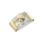
I picked a small (1007 package or 1.8mm x 2.5mm) 470uH inductor: TAIYO YUDEN LB2518T471K
Photodiodes
The choice of photodiodes, energy storage and power management really all go hand in hand:
- if you pick diodes which give you too low a voltage under certain light conditions, you may not produce enough during the day to actually charge up your storage solution
- if you pick diodes (or arrange them in series) to maximise your voltage output, you may do so at the expense of the current you generate (and then you waste it in a diode or a LDO - buck converters are expensive and take up space) and you may very well go above the rating of your energy storage choice (a supercap rated for 5.5V or a LiPo battery which should not exceed 4.2V for instance)
- if you try and maximise your current output, you may do so at the expense of your voltage, which without a boost converter will only rarely generate enough voltage to actually power your MCU+LED or even recharge your energy storage solution
- if you pick beefy (in terms of voltage and current generated) photodiodes, they may be too big to actually fit your space-constrained board, or you may have to move components to the bottom of the board which then drastically increases production costs)
Many hobby projects I came across used BPW34 photodiodes (several variants - SMD or THT, -S version or not), but:
- they are expensive (£0.424 per piece for 100 units)
- they are big (up to 4.0mm x 6.2mm including leads)
So I went hunting for other photodiodes with an interesting combo of the following properties:
- open-circuit voltage
- non-ridiculous photocurrent (say >5uA at least - keep in mind that the ATtiny eats most of that when asleep!)
- price
- availability (incl. on LCSC/JLCPCB for easy manufacturing)
- size (to cram as many as possible and maybe play with series/parallel configurations)
I ordered 4 types, did some very unscientific open circuit voltage measurement for them under similar conditions, and summarised my findings in this handy comparison/decision table:
| BPW 34 S | ZPD-Z3227C-10-Z3 | PD15-22C/TR8 | PD70-01C/TR7(ORI) | |
|---|---|---|---|---|
| Supplier | Mouser | LCSC | LCSC | LCSC |
| Unit price (£) | £0.720 | £0.059 | £0.098 | £0.185 |
| Unit price (n=10) (£) | £0.551 | £0.059 | £0.098 | £0.185 |
| Open circuit voltage (mV) | 365 | 410 | 410 | ? |
| Current (uA) | 55 | 8 | 6.5 | 25 |
| Size W (mm) | 4 | 2.7 | 2.8 | 3.9 |
| Size L (mm) | 6.7 | 3.2 | 3.3 | 6.4 |
| Size mm2 | 26.8 | 8.64 | 9.24 | 24.96 |
| Number needed for 3.3V | 9.0 | 8.0 | 8.0 | |
| # on lampion2 PCB (assuming 8 BPW34) | 8.0 | 24.8 | 23.2 | 8.6 |
| # in parallel | 0.88 | 3.08 | 2.88 | |
| Current in parallel (uA) | 24 | 13 | ||
| Measurements | ||||
| Open circuit voltage (measured, cloudy day, blinds closed) | 315 | 287 | 283 | 300 |
| by the window | 340 | 313 | 315 | 338 |
| Number needed for 3.3V (worst case scenario) | 10.5 | 11.5 | 11.7 | 11.0 |
| Number needed for 3.3V (avg scenario) | 9.7 | 10.5 | 10.5 | 9.8 |
| # in parallel (worst) | 0.76 | 2.16 | 1.99 | 0.78 |
| # in parallel (avg) | 0.82 | 2.35 | 2.21 | 0.88 |
| Current in parallel avg (uA) | 16 | 13 | ||
| Cost for max diodes on PCB | £5.760 | £1.171 | £1.957 | £1.477 |
My winner is the Chau Light ZPD-Z3227C-10-Z3 in a 10s2p configuration, costing £1.171 for the 20 pieces needed per board. It should produce 3.3V @ 16uA under decent light conditions.
And my own 3d model of it:
Energy storage
This choice means that we should reasonably expect to generate 3.3V (in open circuit at least…) during the day, if the device is placed somewhat close to a window. Reaching 3.7V or even 4.2V will happen, but a lot less often/reliably.
So the previous choice of photodiodes really constrained my options in terms of energy storage - LiPo or lithium batteries were not an option without a boost converter, and I was trying to keep things small, cheap, manufacturable :)
At these current levels I would have just trickle charged them anyway, no need to a charging IC, but I may have had to add some over-discharge protection nonetheless.
Since lithium based batteries are a pain to deal with when shipping (especially LiPo batteries) and given the voltage constraints I had just created for myself, I decided to go the supercapacitor route. There is a 5.5V 1F supercap which does the job, the Lelon SCMDVLT5R5105ZVC205007E (£2-3 per unit in small quantities though)
Power management
When there is enough light, the photodiodes should charge the supercap. Easy, we just connect their output to the supercap’s positive pin.
The MCU then uses the supercap’s energy to power itself and switch the MOSFET which loads the inductor.
When there is not enough light, the supercap acts as before, but it should not discharge into the photodiodes (which would now be forward biased). This is achieved using a Schottky diode (to minimise voltage drop), this specific 1N5819WS which is a JLCPCB basic part and small enough (power dissipation capabilities do not matter here given the currents we are dealing with).
Something interesting is going on here though. The diode states that its voltage drop Vf should be 0.6 to 0.9V:
0.6V is a massive loss when we are dealing with such tiny amounts of power gleaned from photodiodes. But wait this is for currents of resp. 1A and 3A! We are operating several orders of magnitudes below that, so how will Vf change for our operating conditions?
Going a little deeper in the datasheet, we find a Vf as a function of I graph. But it stops at ~6mA.
As you can see with my perfect linear extrapolation, we are likely to only have a much smaller voltage drop across the diode when we try and only get 10s of uAs through it. When I measured it, I observed a drop of ~40mV when some natural light was on, so I think that the current going through the diode was around that order of magnitude.
Now if there is too much light and the photodiodes produce a voltage above what the supercap is rated for (5.5V), we should somehow manage that voltage and bring it safely below 5.5V to charge the supercap.
The first idea that came to mind when thinking about this, because I had seen it in so many projects (including very low power ones like this one), was to use a Zener diode with a Zener voltage Vz of ~5V, and voila. All the power would feed the cap when the voltage was below 5V, and the voltage would be clamped to 5V if it ever tried to go above. Done.
Well, not so fast.
Let’s look at the MM3Z5V1B (Extended part with a thumbs up, which means Basic really). The “5V1” in the name means Vz = 5.1V.
Let’s look at the definition of various curve points for the Zener diode:
For our diode, we have the following electrical characteristics:
So when the diode is reverse biased with ~5V, it effectively sinks 5mA worth of current. Ok.
But when it’s 1.5V is eats 2uA! At 1.5V we don’t really care since we won’t go that low, but we do care about voltages in the range 1.9V - 5V, which is when charging the supercap matters.
The Vz / Iz curve looks like this, and once again it does not cover the whole range we are interested in, so let’s extrapolate coarsely:
Between 1.9V and 5V, the Zener will eat 10nA to 10uA (provided the extrapolation is remotely correct). At the lowest voltages, where it’s very critical to try and top up the capacitor (provided its own voltage is below that minus the Schittky’s Vf discussed above), at least the Zener diode won’t be eating too much current. We’ll have to test it in real life to see if it’s a deal breaker.
An alternative to a Zener diode is to use a LDO, I think. When above it’s output voltage, say 5V, the LDO would dissipate the voltage difference and stabilise the output at 5V. When the input voltage is below the set output voltage, it should just output it. Let’s see.
The XC6206P332MR-G is cheap, small, and a basic part on JLCPCB. Its output is set at 3.3V though and really I should be able to go to 5V safely. It has a supply current of ~1uA, the output voltage seems to reflect the input voltage (below is set output voltage) quite nicely. There’s also a -P502 version available with a set output voltage of 5V. It’s cheap and in store, just not a basic part.
Yet another alternative would be to use a voltage supervisor, active low, with a threshold of 5V. TODO.
Ambient light detection
In order to save even more power, I wanted to find a cheap (in terms of £ and in terms of power draw) way to monitor ambient light in order to tell the MCU not to pulse the LED when it’s daytime, which would save between 8 and 16 hours a day, depending on the season and your latitude.
Analog/digital read
On option is to just measure the voltage produced by the photodiodes using the ATtiny. Without checking, I assume that using the ADC is painful to set up and maybe costly in terms of time and/or current draw. Also I would need to scale down the voltage of the diodes since it can reach >5V and definitely more than the ATtiny’s Vcc, which is Vcapacitor.
So I might as well try and use a voltage divider to bring the voltage down and read the input as a digital one, which is much easier to do (and maybe faster/cheaper as well).
From the datasheet:
- Input is high from 0.6 to 0.7*VCC
- Low until 0.2 to 0.3*VCC
VCC is VCAP, between 2.9V and 3.3-5V (LDO or Zener).
If cap is very full, it’s OK to keep the light on anyway.
So what we absolutely want is that when VCC=VCAP is under 3V, and when V_PHOTO is <2V,
the input is read as low.
So we want the input to be under 0.3 * VCC = 0.3 * 3 = 0.9V
when the top of that voltage divider is 2V.
So we want a 55% reduction, so like 110k / 90k.
Now we have 100k resistors in the schematic so we can easily do a 50/50 divider. Since that will also be on (no MOSFET to toggle measurement to save BOM/space), it will cost me 3.3V / 200k = 16.5uA. That actually sounds crazy now that I do the math, I need bigger resistors (none available as Basic components on JLCPCB) or another solution altogether. WIth such resistors I would lose more in the voltage divider than I would save by turning off the LED…
2V on photodiodes and 3V on cap will read 1V on the divider, which is above the 0.9V threshold.
The cutoff will be at 1.8V from V_PHOTO, which is acceptable too.
This is implemented on the test board rev 2, let’s see how that goes.
Voltage supervisor
I could also use a voltage supervisor (push/pull and active high) to power the MCU directly. These can typically source 10mA at least, which is far enough for us (saves a MOSFET and gate resistor I guess).
Some consume very low currents, like the BU4926G (and the whole BU48/BU49 series) and are somewhat cheap (exact parts depend though), or the Torex XC6126 series or XC61CC2002MR-G.
Now the problem is: I want to power the MCU when the monitored voltage is low (below the threshold monitored). So I can;t use that to power the MCU. I need to invert thge signal and use Vcap to power the MCU instead, which adds a P-channel MOSFET to the BOM (I can use the good old AO3401A from JLCPCB, cheap and Basic, but will I have enough board space?)
Software
Power saving approach
Same as Everled basically.
Ambient light detection
TODO, but see hardware considerations above
Power budget breakdown
WIP consumption:
LDO/Zener diode
MCU (awake/asleep)
Resistor network
MOSFET pulldown
LED pulses
Supercap self discharge
Board design
Test board

| Designator | Description |
|---|---|
| 1 | Real size board outline and footprints |
| 2 | Board wing for programming/debug pins |
| 3 | 9x BPW34 photodiodes |
| 4 | Footprint for coincell battery holder |
| 5 | Schottky diode |
| 6 | Zener diode (unpopulated here) |
| 7 | MOSFET and pulldown resistor |
| 8 | ATtiny85 |
| 9 | Status LED + resistor |
| 10 | Footprints for LEDs |
| 11 | Footprints for inductors |
| 12 | Supercapacitor |
Board to size
The goal is to fit everything in that tiny jar. This makes programming the bloody ATtiny85 using ICSP difficult unless I use a pogo pins programming jig and I did not want to do that just yet (maybe if I make hundreds one day).
So instead I laid out all the components on a round PCB which would fit inside the jar, but left programming pads (and test pads) on a brekable PCB extension using mousebites. Not ideal for the “manufacturing” requirement since it involves manual post-processing, but it gets the job done.
Panelling
TODO
Costs breakdown
TODO
Random thoughts for later
- are newer ATtinies with UPDI cheaper/easier to program/ more power efficient?
- can I/ shall I use a WCH RISC-V MCU instead? or a puya (these are ARM Cortex MCUs, probably overkill like the STM32s)? or a OTP cheap-ass MCU like the 3 cents ones?
- is there a world when adding some kind of a lens to capture more/focus more light on the photodiodes is worth doing? 3d print a case with an embedded Fresnel lens?
- in a similar vein, would the LED benefit from a reflector and/or a diffuser?
- I really need a microamp-level measurement device for my scope
- Anysolar cells? Some are small and way overpowered which leaves a lot of room for improvements