 Ted Yapo
Concept
This is a project born of frustration. As an amateur astronomer and astrophotographer, I often find myself stumbling around expensive and fragile equipment in the dark. A few years ago, I went looking for glow-in-the-dark markers I could attach to tripod legs and other gear to avoid costly accidents. I quickly dismissed traditional glow-in-the-dark (phosphorescent) materials because of their short half-life and the need to "charge" them before use. Chemiluminescent markers (glow sticks) are better in this regard, but are too expensive to continually replace, and end up in landfills after one night's use. Radioactive markers (especially tritium-based), with their constant glow and multi-year half-life, are technically almost perfect for this application: you can stick them to equipment and you're done. The problem with tritium markers is that they're not legal for manufacture or sale as general-purpose consumer devices in the United States (watches, compasses, and gun sights are exceptions). Even where they are legal, they are still quite expensive. This leaves electronic markers, but these often share similar shortcomings with other glow-in-the-dark technologies: constantly charging or replacing batteries, short-duration illumination, or high long-term cost. What I wanted was a small constantly-glowing LED that I could put somewhere and not have to service for a year or more. Unfortunately, most portable LED lamps are designed as flashlights - they emit a relatively powerful beam for a short duration (hours or days) per battery or charge. There's a race in the industry to make brighter and brighter lights. I wanted to go the other way: relatively dim lights, useful in dark situations, that maximized runtime.
Hazards
Lithium battery powered devices are more dangerous than small tritium light sources, despite the NRC's paternalistic approach and the general public's fear of "radiation." According to the Energizer CR2032 datasheet, an ingested lithium battery can lead to serious injury or death in as little as 2 hours. Further, improperly stored coin cell batteries can short out and cause fires or burst and cause chemical damage. These batteries must be kept out of reach of children and pets at all times, and following Energizer's advice, batteries should be held in compartments with captive screws or other childproof latching devices. While the neat little glowing LEDs may look like a fun thing for a child to play with, children should not be allowed to play with these devices.
Version 3.0
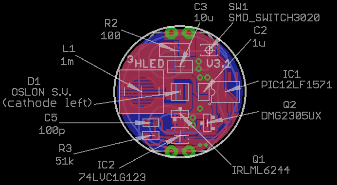
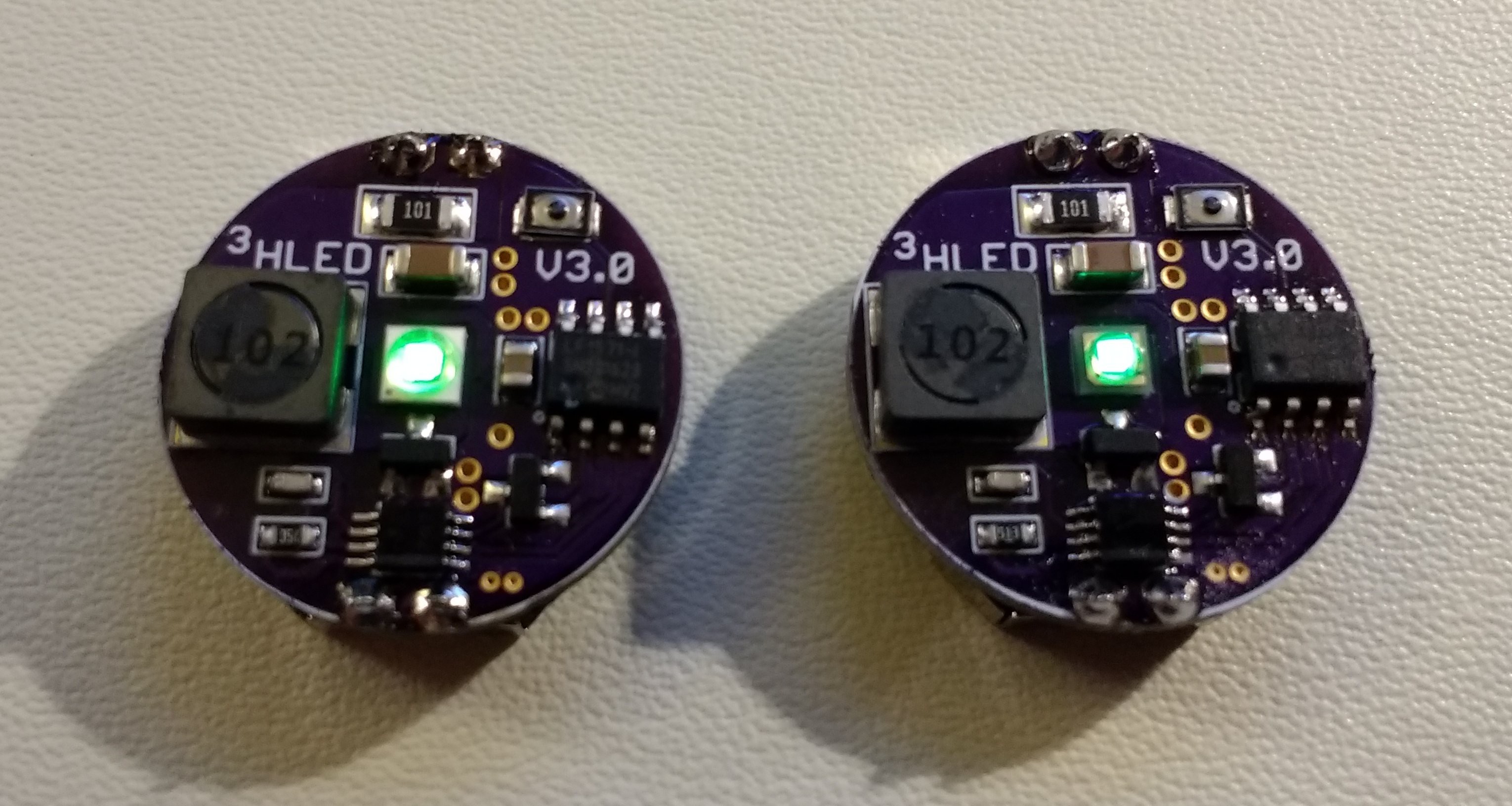
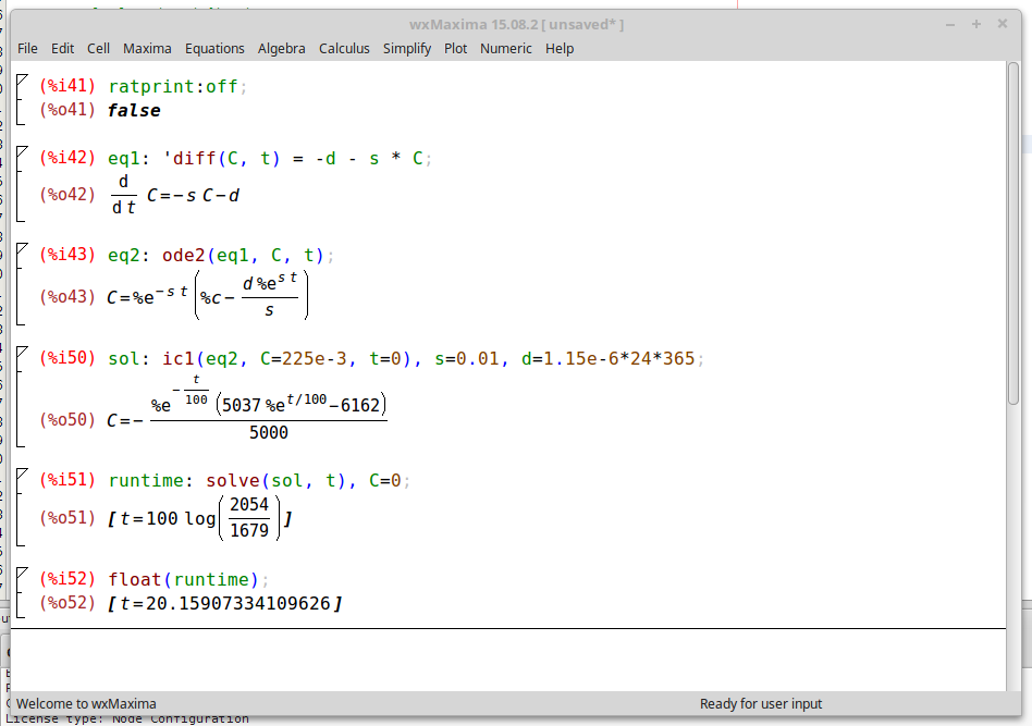
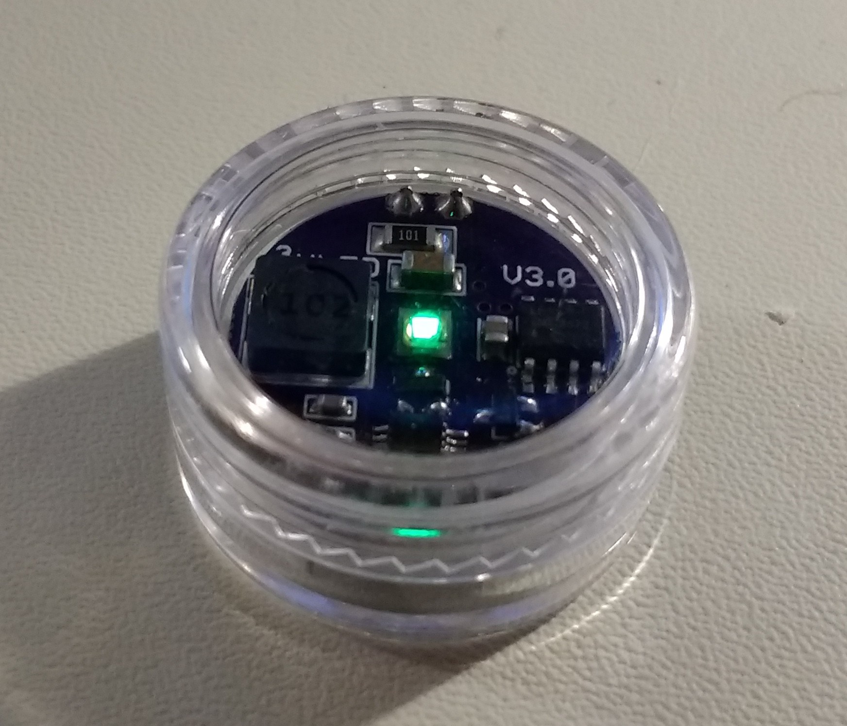
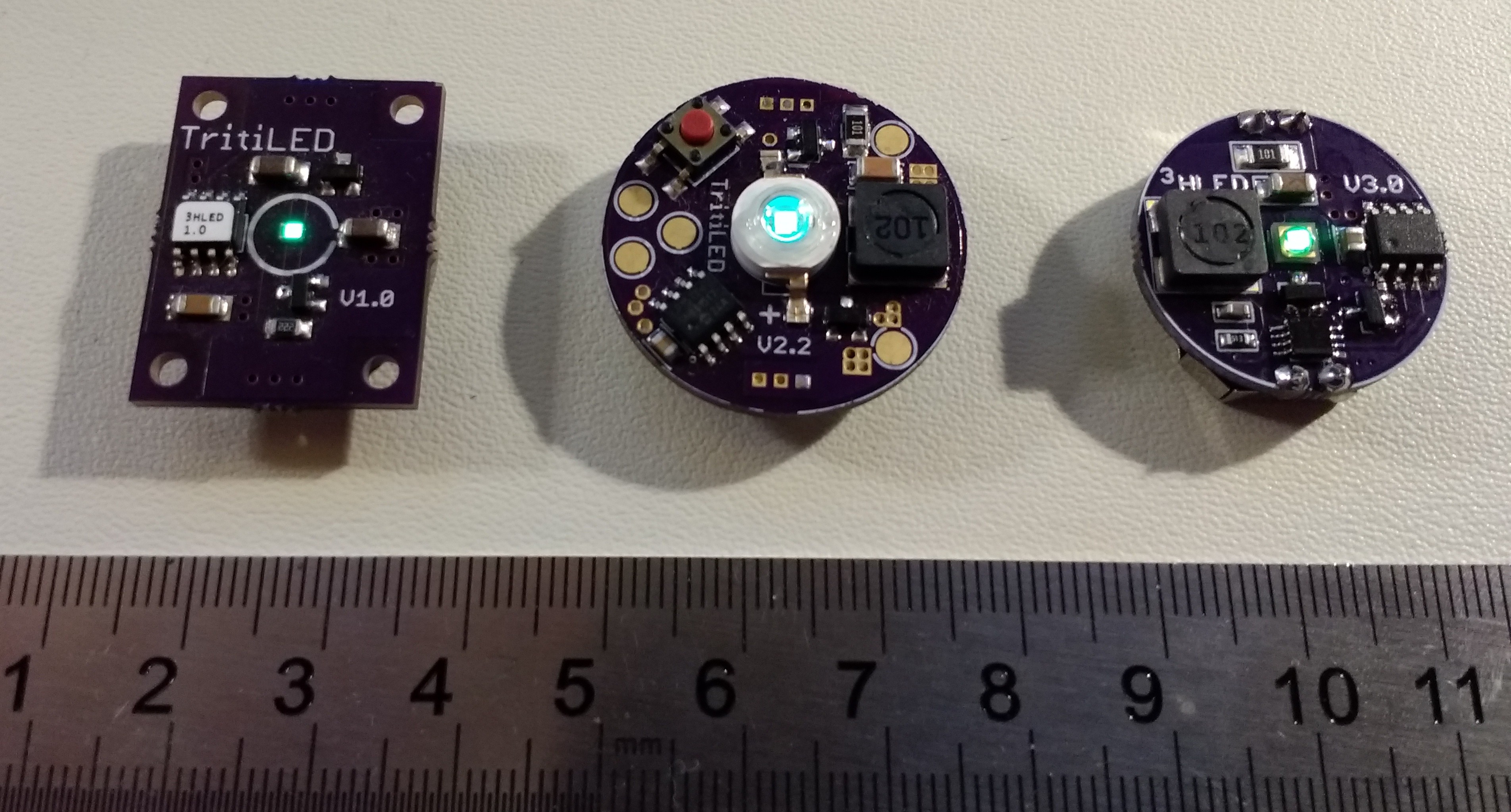
Version 3.0 uses a new architecture with the PIC12LF1571's synchronized 16-bit PWM outputs controling a 74LVC1G123 monostable producing the current pulses. This allows tuning the peak pulse current to optimize LED efficiency, while separately tuning the overall brightness (and associated battery life).
This version allows the use of three different LEDs, chosen for their unique characteristics. Each runs for a configurable 1-10 years (or longer) from a CR2032 cell. At minimum brightness, the circuit is estimated to run from 17.6 to 20.2 years on a CR2032.
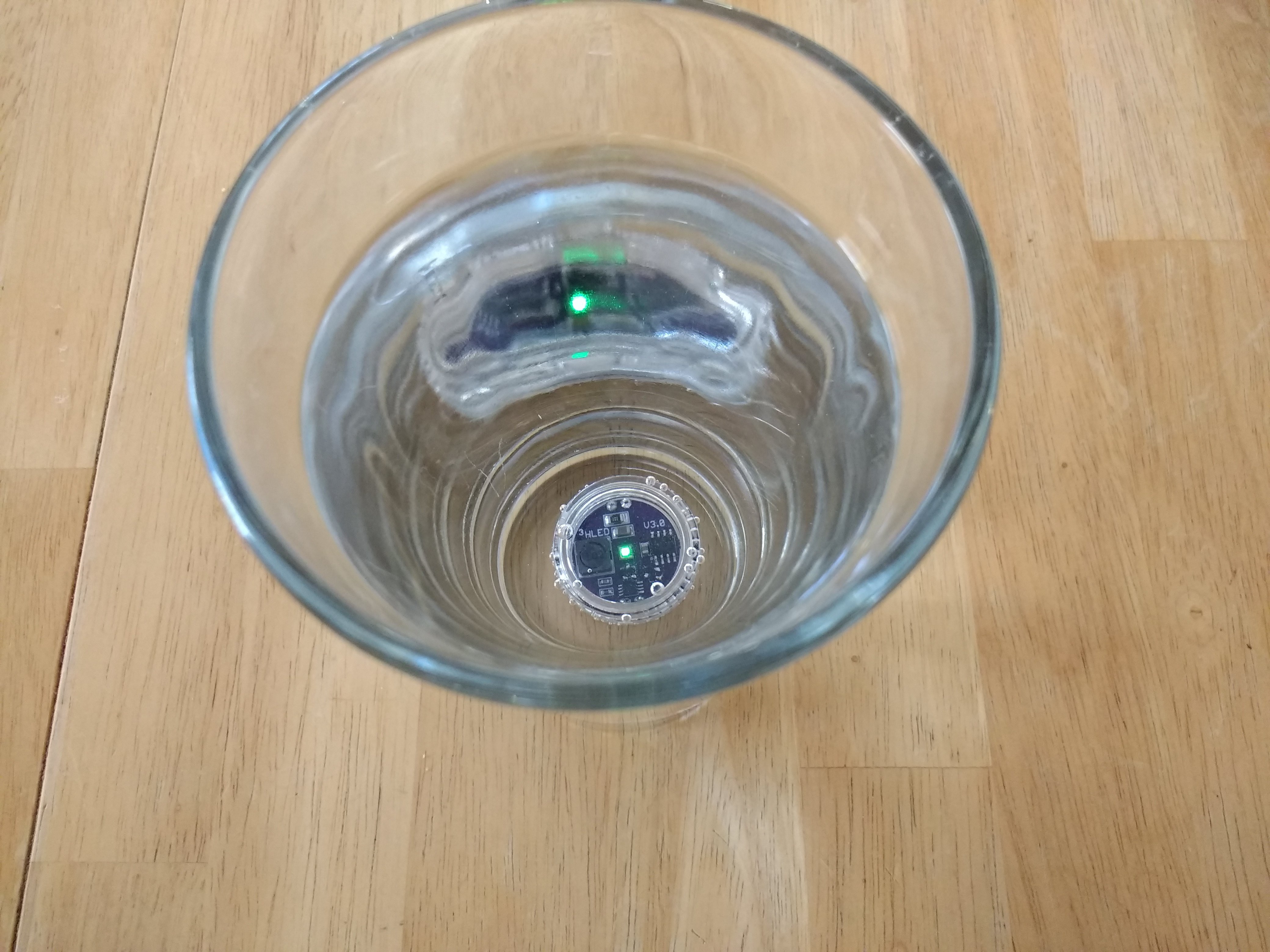
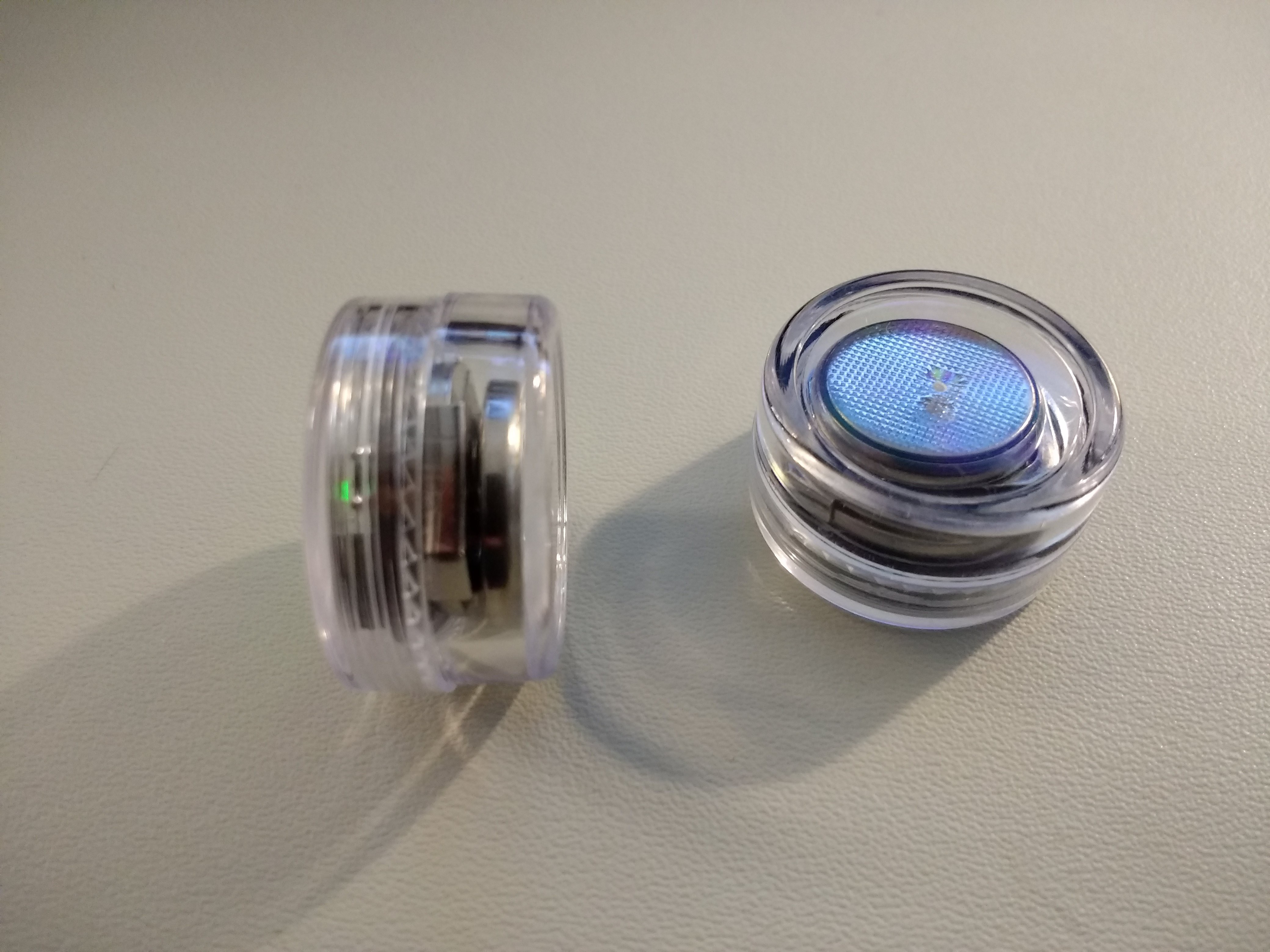
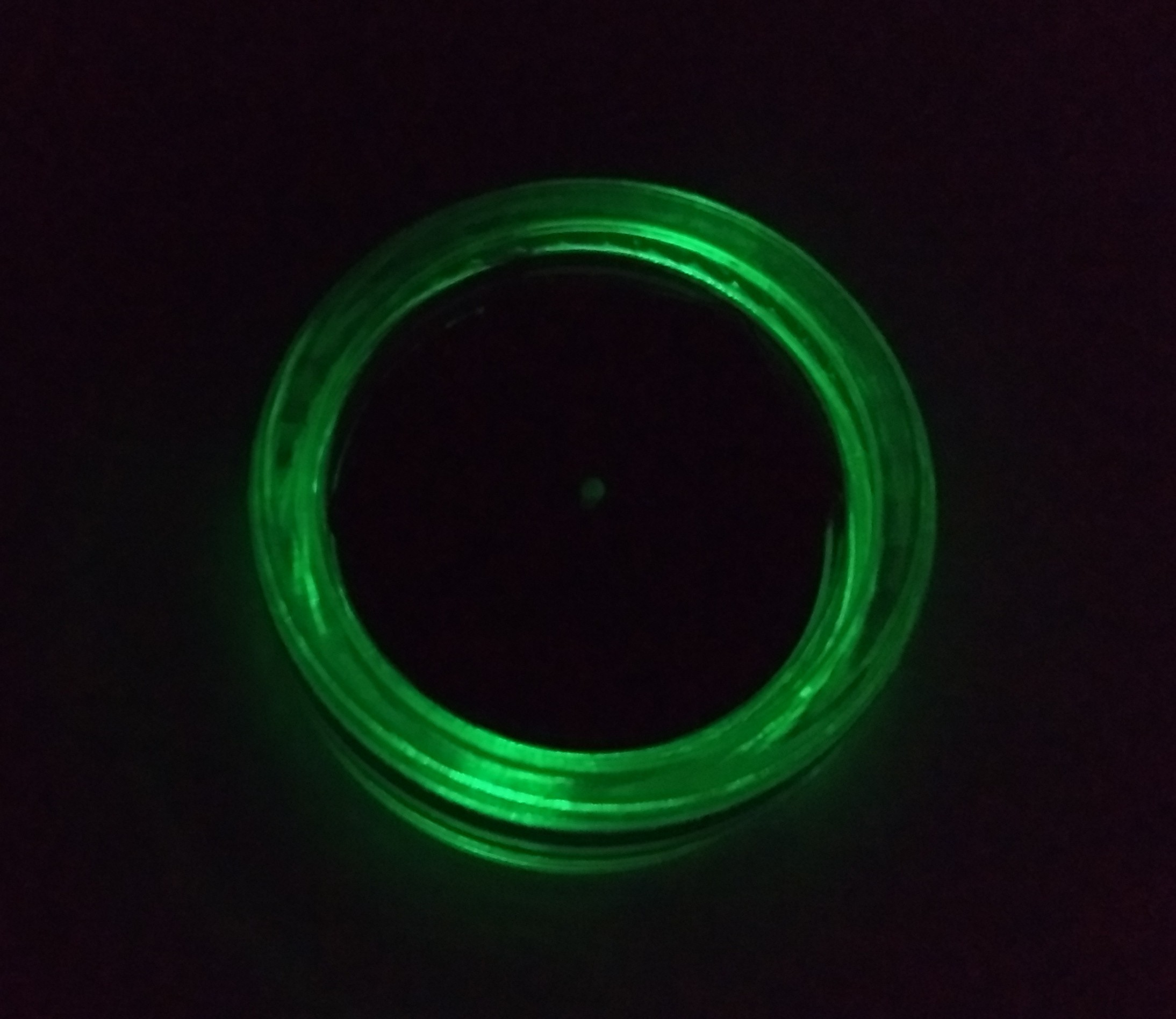
The V3.0 PCB with battery fits inside inexpensive "5g" plastic jars for weatherproofing. The jars can be permanently sealed with silicone sealant or epoxy if you don't mind breaking a $0.16 jar when you need to replace the battery in a few years.
Details of the 3.0 version can be found in the build log.
Version 2.x
Version 2.x improves on the earlier design by driving the LED at close to maximum efficiency using a simple inductor-based boost circuit. This design also features:
- Selectable brightness / run-time trade-off (at program time)
- Bright blinking modes (constant / fast blink / slow blink) with constant runtime
- Inexpensive LEDs in many colors
Due to the higher electrical and LED drive efficiency, the V2.2 circuit will run for 5 years on a CR2032 (minimum brightness). The brightness can be...
Read more »
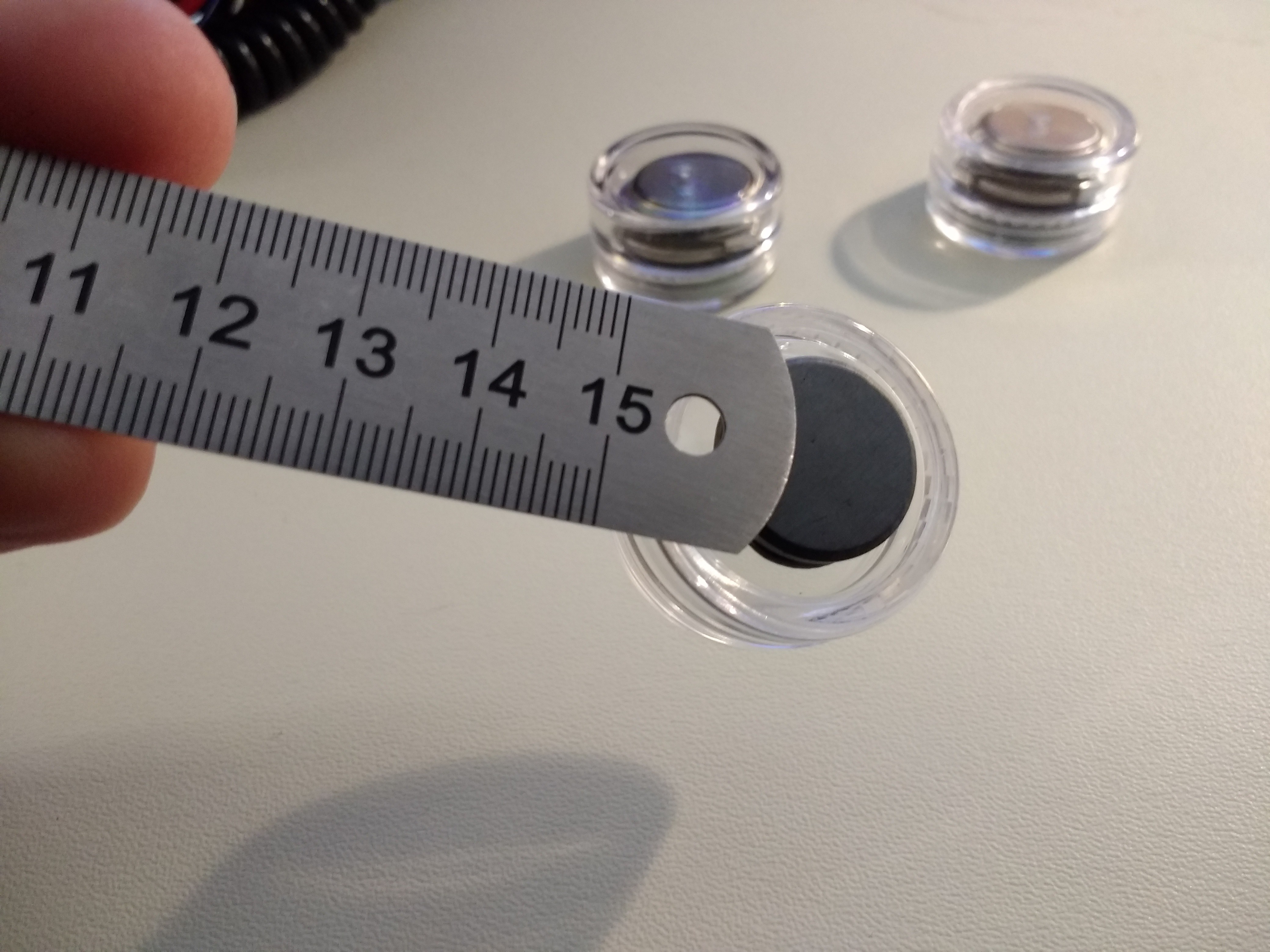
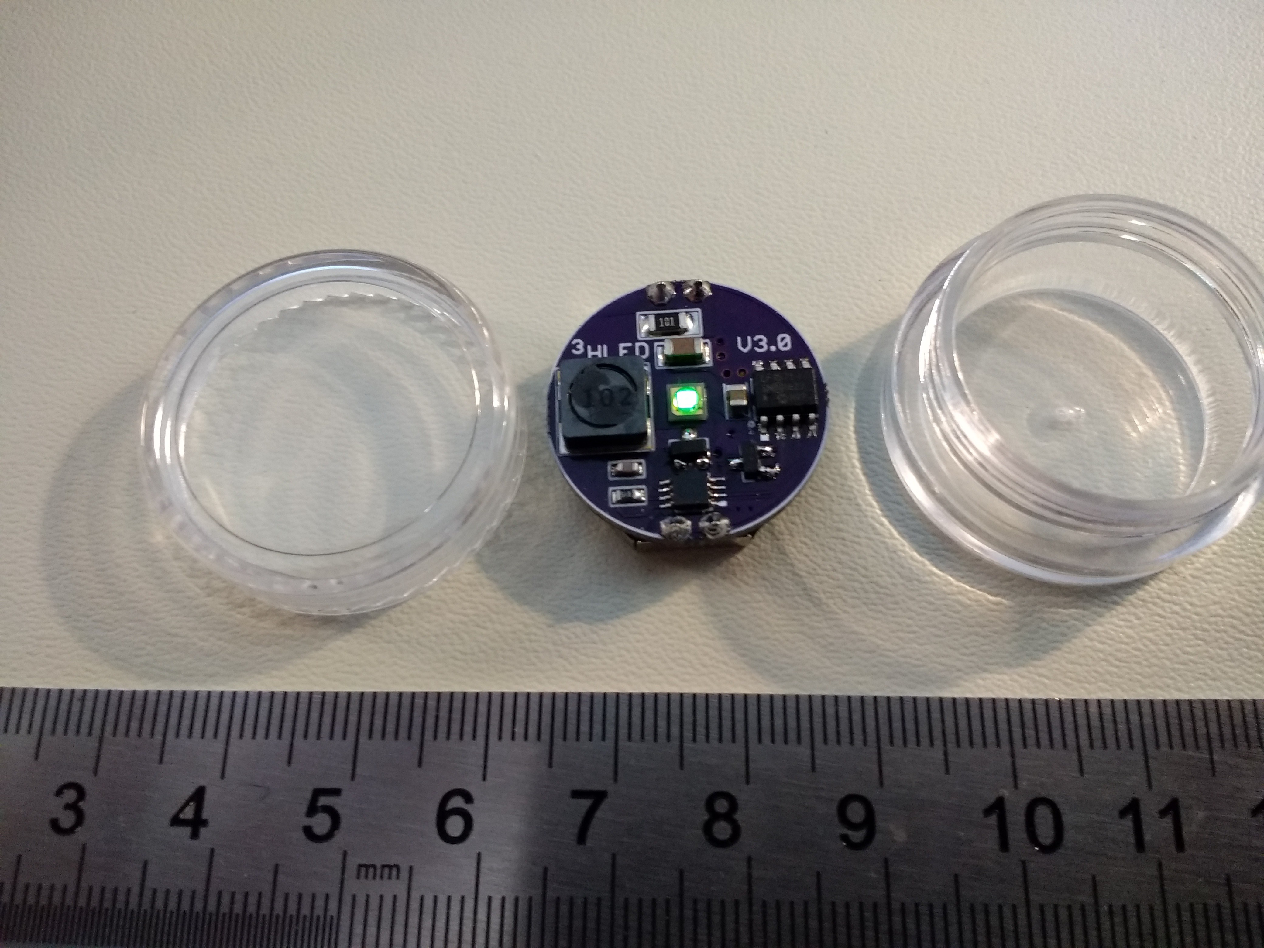 The PCB uses a through-hole CR2032 holder (smaller than the SMT version), allowing it to fit in the jar.
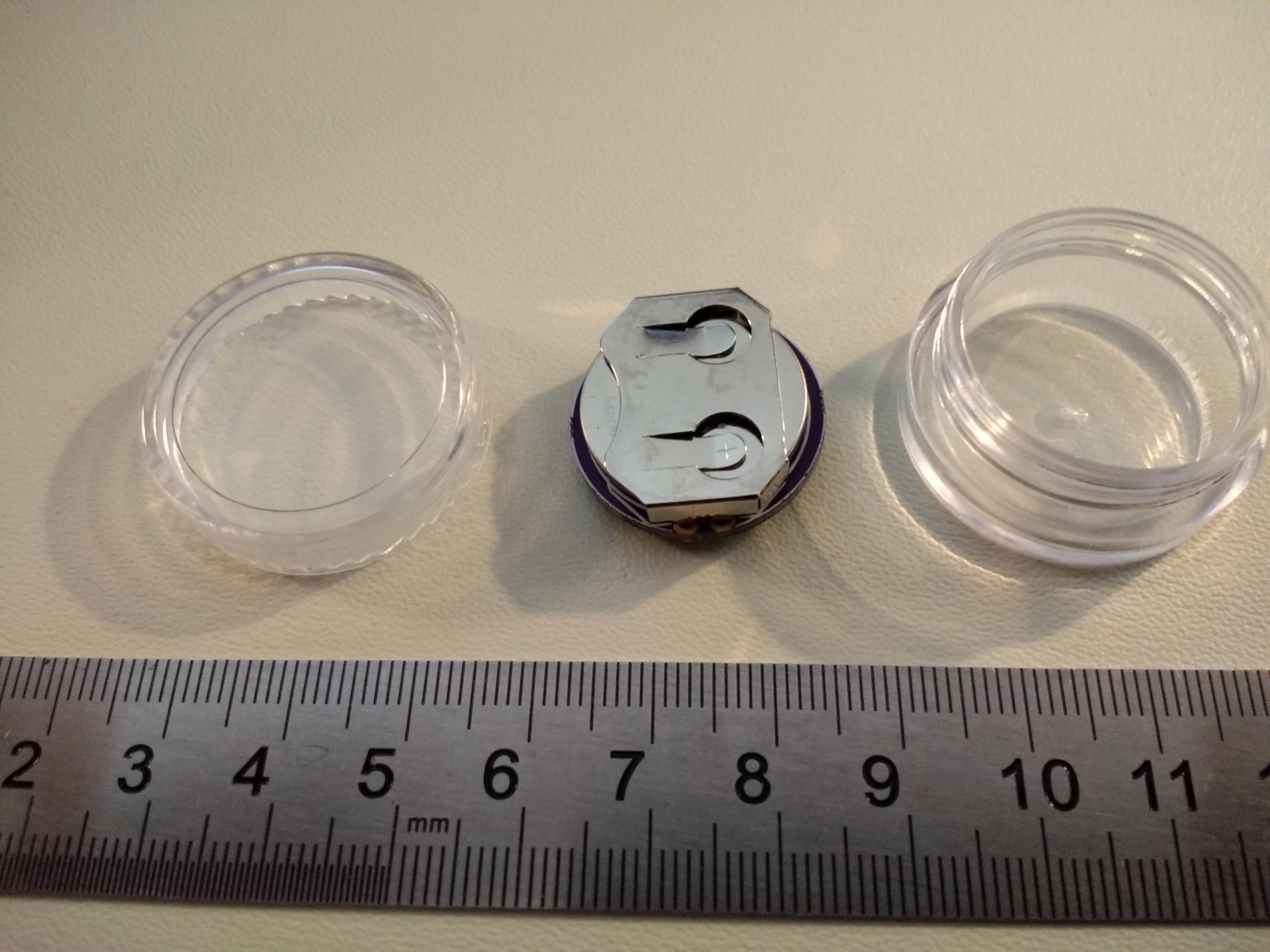


 Sam Ettinger
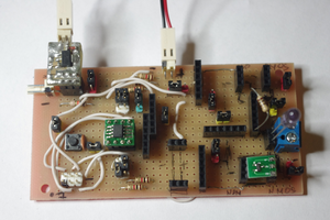
 piotrb5e3
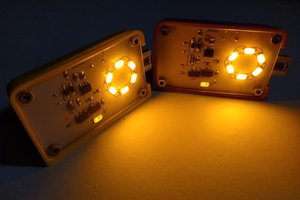
 Simon Merrett
 Christoph Tack
one simple questions.
Why not add a light sensor and periodically turn the lights off or down when it's bright enough?