Close
0%
0%

The [original] AI Business Card

Remaking my business card to run Eliza on a cheap ARM SOC.

Similar projects worth following
My entry in the 2024 Business Card Contest is a single-chip computer running the original "AI" - Joseph Weizenbaum's Eliza natural language processing computer program developed from 1964 to 1967 at MIT. I want to make something I can actually hand out to people so that means, aside from being fun, it has to be inexpensive and easy to build, and should be as thin as possible. Read on to see how I got started, the meanderings I took along the way and how the final device came together.

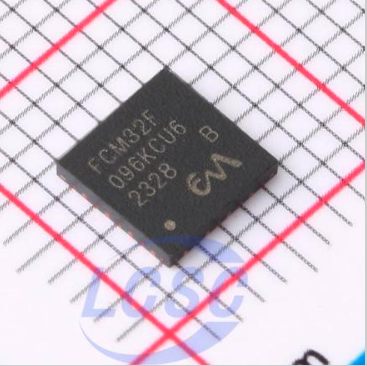
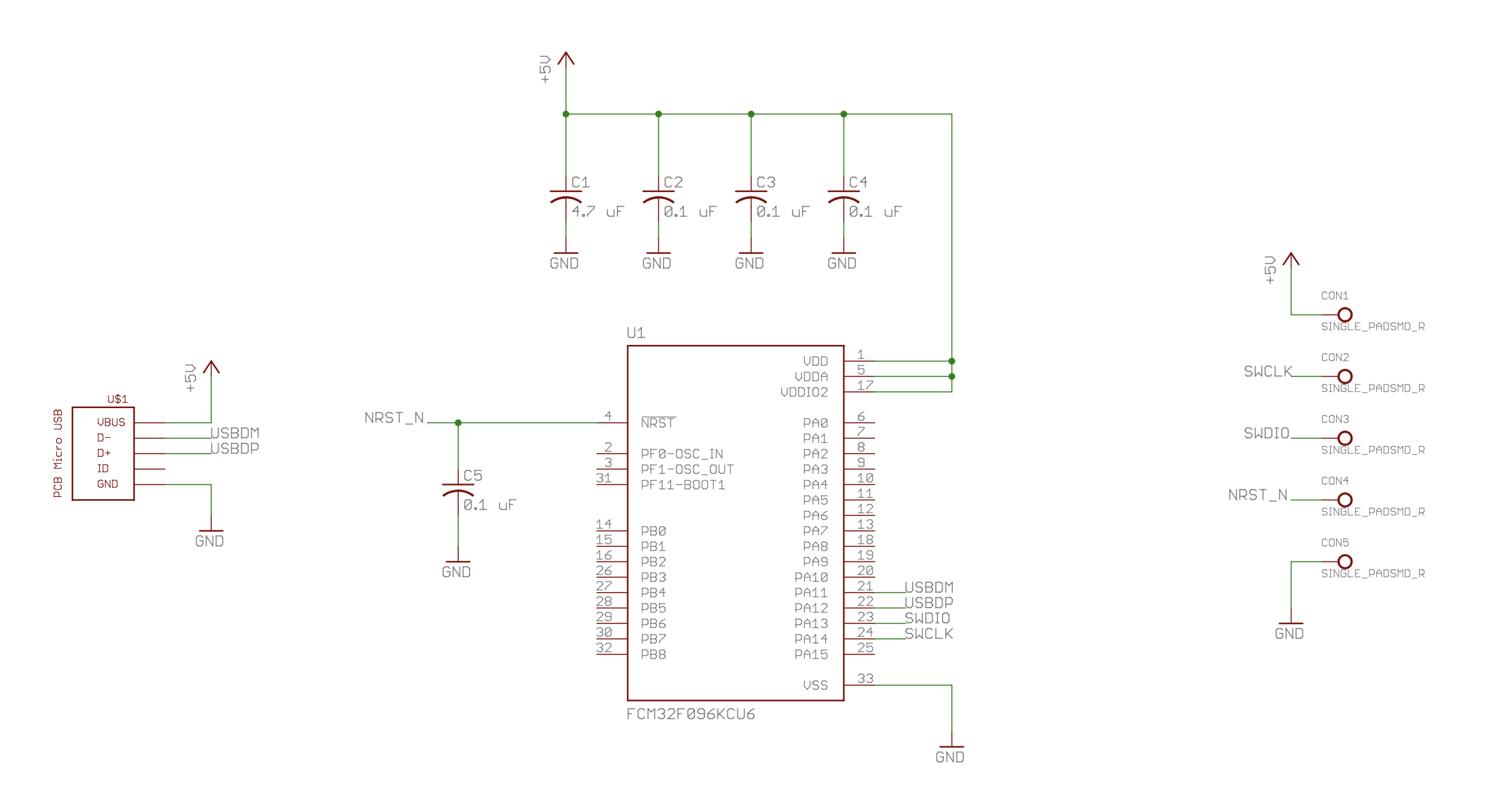
I wasn't planning to enter the contest.  However that changed when I stumbled across a cheap STM32 almost-clone chip on LCSC.  I had started by looking at clones of STM32 chips for another project and I came across a company called Flashchip.  LCSC was selling a FCM32F103 series of chips which clearly were copies of the venerable STM32F103.  But interestingly, the Flashchip website no longer listed this chip.  I wondered if lawyers had been involved.  What they had were some chips that didn't quite match ST's numbering system but had similar features (take that, ST lawyers...).  In particular I found the FCM32F096KCU6 that has some intriguing attributes.   Specifically it has a USB interface and it can run directly on 5V.  Whoa - one could build a single-chip USB doo-hickey with no need for other parts like a 3.3V LDO. 

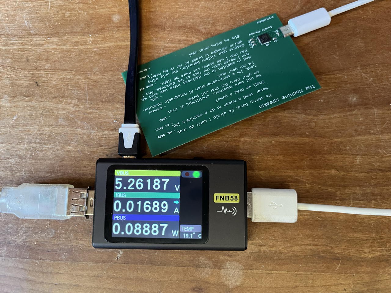
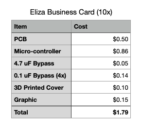
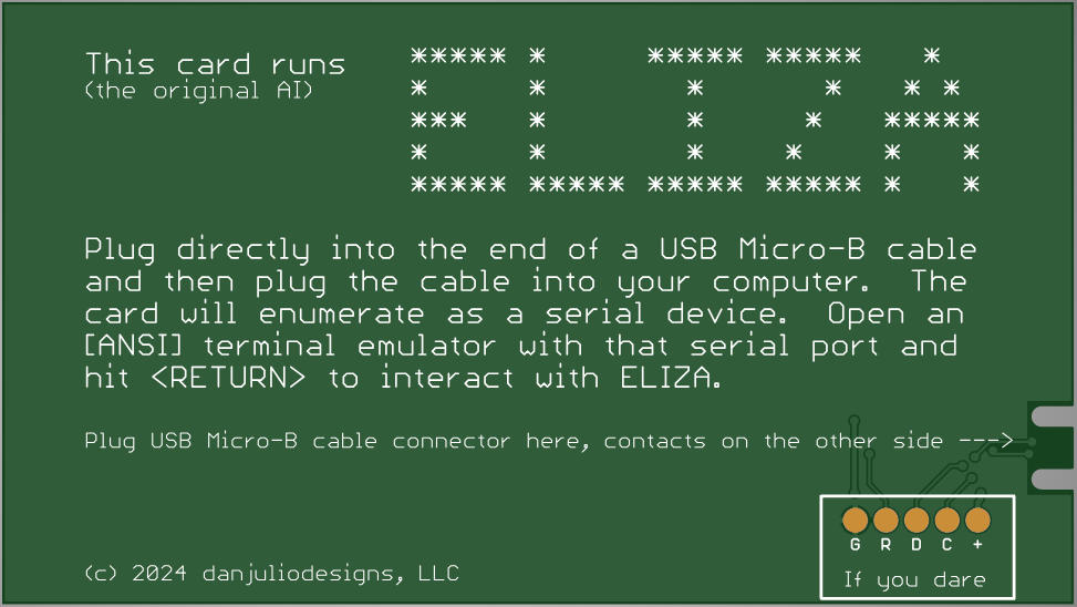
That's when I thought mmm... maybe I could design an interesting business card around this and rise to the glory that is a Digi-Key gift card.  That is if I could figure out how to program it (of course - in reality - I quick-fingered in an order for 11 parts before I really thought about the issues I'd run into later).

What to run on it was the next question.  The hacks necessary to program it weren't yet on the radar.

eliza_code_release.zip

Firmware + readme (minus the proprietary ST code)

Zip Archive - 1.88 MB - 06/28/2024 at 21:19

Download

eliza_r1_stencil.zip

Top Stencil

Zip Archive - 6.19 kB - 06/26/2024 at 17:58

Download

eliza_r1_gerber.zip

Gerbers

Zip Archive - 50.25 kB - 06/26/2024 at 17:57

Download

eliza_schem.pdf

Schematic

Adobe Portable Document Format - 22.66 kB - 06/26/2024 at 17:55

Preview

3d_spacer.zip

OpenSCAD + STL for the spacer

Zip Archive - 1.34 kB - 06/26/2024 at 17:54

Download

View all 7 files

  • Fin...for now

    Dan Julio6 hours ago 0 comments

    Of course I spent much more time than I originally imagined but the project was fun, taught me a few things about ST's tools and Chinese clone chips, and left me with some new business cards to hand out.  I've given away two and the recipients were both amused so that's a success.

    I've also learned a few things that I will address if I ever revisit this project.

    1. I'll add a ground pour on the top layer of the PCB.  I didn't originally because I wanted to minimize thickness but my 0.6mm PCBs suffer from a slight warping that I think is due to the ground pour on the bottom of the PCB.
    2. I'll look into an open-source USB stack like Dmitry Filimonchuk's libusb_stm32 or Ha Thach's tinyusb as well as a command-line only development environment to get away from any restrictions on distributing the full source code and compiled binaries.
    3. I'll redo my graphic to fit in the empty space on top of the PCB so that all the text on the top PCB is visible.

    I hope anyone who's spent time reading has enjoyed this project.

  • Power Consumption

    Dan Julioa day ago 0 comments

    Eat your heart out, ChatGPT ;-)  About 90 mW when connected and active.

  • Cost Analysis

    Dan Julio2 days ago 0 comments

    I ended up building 11 boards (I got an extra from PCBWay and I had ordered 11 micro-controllers).  However one board refuses to work and I can only surmise that I damaged the micro somehow (I did rework it a couple of times).  So my cost breakdown is for 10 boards.

    Notes:

    1. Shipping not included because parts for this project tagged along on orders for other projects.
    2. Raw PCBs and components were at 10x qty.
    3. 3D Printed Cover estimate from PrusaSlicer
    4. Graphic was setup 10x per glossy sheet at about $1.50 per sheet at Kinkos.
    5. Doubly Sticky tape cost not included (but very minimal)

    Since I was doing this for fun my time is not included either but as one might imagine far dominates all other costs.

  • ELIZA in action

    Dan Julio3 days ago 0 comments

    I made a short video showing the business card in action.

  • Turning on the hardware

    Dan Julio5 days ago 0 comments

    Once the 'F103-based project was up and running on the dev board I ported my code to a new project based on the STM32F042K6.  That went pretty smoothly but of course the final link stage would fail because the code size and RAM requirements exceed that of the part.  Fortunately this information is defined in the automatically generated linker script and it was easy enough to change the Flash length to 256KB and RAM to 24KB.  Now I actually had data to try to load into the hardware when the PCBs arrived. (Edit: the firmware, minus the proprietary ST USB device library is in the Files section).

    Assembling the PCB was trivial so I excitedly built up a wiring harness with a set of pogo-pins plugged into a 0.1" header that had a male header on the other side and could connect to either the ST or Flashchip dev board programmers.

    To program I just press the pogo pins against the SMT pads on an assembled PCB and manipulate the PC with my other hand.  Not as elegant as some ICSP headers but it works well-enough.  For volume production it would be easy to design and 3D print a programming fixture which could hold the target board and ICSP header in place.

    (the clip supplies 3.3V to the card)

    My first attempt at programming was a failure.  I tried to use the STLink programmer from within STM32CubeIDE.  The Flashchip chip ID was unrecognized and the programmer refused to even try.  I'm not familiar enough with the way the programming software works under the hood to try other things, so after a little googling, I abandoned this approach.

    Next up was to try the Flashchip dev board DAPlink programmer.  I figured their programmer would recognized their own chip.  Again, no go.  Each programming attempt resulted in a FAIL file.  Sometimes it just hung downloading the file to the board.  Arghh.   Now I was a little worried.

    My previous searches revealed the existence of the STM32CubeProgammer software.  Thinking it might be a little more flexible I downloaded it on the PC.  Connecting to the STLink programmer actually resulted in successful communication with the 'F096 and I was psyched to press the program button.  Woo-hoo, programming was successful.  Quickly I plugged the board into USB and looked to see if a USB Serial port enumerated.  No go.  Nothing.  It was dead.  So back to the programming software and reading the flash back.  It looked OK.  The beginning matched the compiled binaries and at the end I saw all the hard-coded strings for ELIZA responses.  What the ???   Then I saw the programming software could compare the read data with  a file.  BOOM.  A entire section in the middle was incorrect.  About 22KB in (of a 46KB program).  No matter what I tried this always occurred.   Once again my lack of knowledge of the ST world left me floundering and I was thinking that this project might be a failure.

    During the various programming attempts I tried plugging and unplugging the STLink programmer.  One time when a previous DAPlink file window was still on the screen (it had reverted to a top-level view when I unplugged the Flashlink dev board) I saw that the STLink programmer was also a DAPlink programmer as Windows changed the window to contain the DAPlink default files.  Huh.  OK, what the hell.  While holding the programming header I dragged the HEX file to the window.  The window went away and then came back after the programmer finished.  No FAIL file.  OMG.  I hurriedly plugged in the USB Micro-B cable to the card.  TADA - I was rewarded with a new serial port!  I started the terminal emulator with that port and hit Return.  ELIZA said hello back to me.  I'm sure you all know that feeling of elation that comes over you after you solve some...

    Read more »

  • The Firmware

    Dan Julio06/22/2024 at 18:06 0 comments

    I started with my port of ELIZA, which itself is a port to C from the MITS BASIC port published in Creative Computing Magazine in 1977.  I put a copy of the article in the files section.  My retrocomputer uses circular buffers (FIFOs) for input and output between the applets like ELIZA and the terminal code so there was also a virtual host API shim to adapt the ELIZA port to those buffers.  I figured it would be a good interface to a USB UART API (and it was).

    What I didn't have was USB UART functionality that would run on the USB peripheral.  I guessed that ST would have some library that ran on their parts and hoped it would work with the Flashchip part. 

    Along with the 'F096 parts, LEDs and buttons I had impulsively purchased from LCSC, I had included a $7USD FCM32F103 development board.  This turned out to be very helpful as their - now discontinued - 'F103 part was sufficiently a clone that it could be programmed by an STLink programmer.

    I used STM32CubeMX and STM32CubeIDE to put together a project for the ST32F103 part with the USB peripheral enabled and a CDC Class USB UART library.  It took a moment to understand how the library worked, and a bit more work on the virtual host shim but the ELIZA re-port itself was pretty quick and in a few days I actually had it up and running.  It was at this point I felt that this whole project might actually be possible.

    The virtual host shim layer really provides two functions.  It pushes and pops characters to and from the USB library buffers, and it implements a couple of utility functions, like clear screen, that the BASIC port had used.  The clear screen function sends the ANSI escape character sequence to clear the terminal screen.  For this reason the output will look a little wonky in a non-ANSI terminal emulator (like CoolTerm which I use on Mac and Windows).

    The major pain point during this test port to the 'F103 was actually programming the part.  The Flashchip development board came with a DAPlink programmer and no matter what I did, I couldn't get it to work.  Programming always failed after I dropped the bin or hex file into the DAPlink folder.

    Fortunately I had another ST development board and I could wire a set programming header to its built-in STlink programmer.  This worked.  The programmer saw the chip as a legit ST part and programmed it.

    No doubt ST would not be happy about this - and, I suspect, they weren't and that's why there is no FCM32F103 part anymore.  But, to be honest, it sure saved me a lot of time to be able to use their tools.

    Technically my use of the ST library on a non-ST part is against the terms of the USB library license agreement and for that reason I don't feel comfortable publishing the complete source code for the whole project (although I will share the code I wrote and the gerbers).

  • The PCB (an homage to TV and movie naughty AIs)

    Dan Julio06/21/2024 at 16:49 0 comments

    The actual circuit is very simple.  The only components are the FCM32F096 and a few bypass capacitors.  I put a 0.1 uF cap on every power input and the reset signal (which has an internal pull-up).  A 4.7 uF bulk cap is less than the maximum 10 uF specified for USB devices to support hot-plugging.  Probably it would work if some of the caps were eliminated.

    The USB connector is from Juan Jesus' Eagle library.  I selected the older USB MIcro-B connector instead of USB-C because it uses a thinner 0.6 mm PCB.  One of the issues in his github repo suggests that using 0.8 mm is better for USB-C.  Check out his work.  It is very inventive and with the proper 3D printed enclosure I'm convinced one could design a USB device that needs no separate USB connector.

    Five SMT pads round out the design for a quick&dirty SWD ICSP programming interface.  Since the 'F096 works with either 5V or 3.3V, it can be powered by either interface.

    PCB Layout of the 89x50mm card was easy.  But since the circuitry takes up so little room I was left with vast expanses of PCB real-estate just begging for artwork of some kind.  Sadly I'm not an artist so I decided to stick with words.

    The back of the card would contain instructions. 

    The 5x5 pixel ELIZA tries to evoke the era of banners on line printers that might have existed at the time the program was originally written.

    I intended the front of the card to be covered by my - or others - printed business card but I wanted to leave a little easter egg so it includes an homage to some of the naughty AIs that have graced our little and big screens over time.  Do you know them all?

    "Card'io Therapy" was what a friend suggested I should call this project.

    The `F096 is nominally 0.8 mm thick, so along with a 0.6mm thick PCB the maximum thickness is slightly more than 1.4mm (accounting for some solder).

    I waited until I had another PCB prototype to build and sent gerbers for this project along with that to PCBWay (no sponserships here, but I do like them) so I wouldn't have to burden this project with the shipping cost.  I selected the basic Green + White also to minimize costs but these would also look very cool in Black + White.

    Next up was to actually write some code.

  • Introducing the FCM32F096KCU6

    Dan Julio06/20/2024 at 18:27 0 comments

    Flashchip's website  is, eh, spartan - as well as insecure.  They list two families of micro-controllers - the F0 series and H0 series.  Clearly they're targeting the low end world.  They list the features and provide a Chinese datasheet for each chip.  It's funny because the datasheets are clearly modeled after ST's, right down to copying figures from them (thankfully...).  No tools.  No discussion about how to program them.

    I scoured the internet and found a document that described differences between their F103 part and ST's F103 part.  It looked like they intended some  high degree of compatibility but not entirely (for example basing their F103 on a M4 core rather than the M3 core in ST's part).   I'm fairly new to the STM32 world and the document gave me hope that I would be able to use the STM32CubeIDE to at least create and compile the project.

    At this point I emailed Flashchip asking if they had English specs and asking how they intend for people to program their parts.  I got a pretty immediate response from someone with the same name that I saw in the Chinese specs I downloaded earlier.  I think Flashchip is a pretty small company.  He sent me a translated datasheet as well as files that are intended to be grafted into ST, IAR or Keil tools that should support their chips.  I've attached the spec to this project.

    The Flashchip F0 series looks a lot like ST's F0 series except with more memory, the formerly mentioned, and very useful, 5V compatibility and some interesting undocumented peripherals like a "LED light strip interface (LLSI)".  But none are a precise match (full clone) of any ST F0 part.

    Sadly, after following the instructions to graft support for the FMC32F096 into STM32CubeIDE, I couldn't get ST's software to list that microcontroller as a possible target.  Maybe the add-ons would have worked with Keil's IDE but I wanted to use STM32CubeMX as the configurator (being lazy and all).

    So I changed tactics.  I had selected the KCU6 variant because it was the smallest package, a 0.8mm QFN32, and would lead to the thinnest business card.  I looked at ST's website to find the closest match.  This seems to be the STM32F042K6 but it has only 32K Flash and 6K RAM (as opposed to 256K Flash and 24K RAM in the FCM32F096).  Even though there was a difference in memory sizes, the pinout, peripheral set and internal addresses seemed pretty much the same between the two devices so I changed my plan to base the project on the STM32F042K6 so I could use the STM32CubeMX configurator and STM32CubeIDE.  I'd deal with memory related problems later.

    Now that I knew what pins to use (a grand total of 4: SWDIO, SWCLK, USBDM, USBDP), I could start the PCB layout.

  • Deciding what it would do

    Dan Julio06/19/2024 at 20:43 0 comments

    I also bought 300 tiny 1.5 x 1.25 mm WS2812B compatible LEDs and 100 tiny little buttons along with the processors - had to make that shipping seem reasonable, right :-)  The graphic I originally designed for my company, danjuliodesigns, LLC, is based around a piece of LED art I made a long time ago so my initial thoughts were things like backlighting that graphic with LEDs and creating colorful patters, or a keyboard with an embedded OLED in the PCB or even some game using some of the buttons and some LEDs.

    Then other people started posting their awesome entries on hackaday.io and I thought oh crap, there go all those ideas.

    After a few days of wondering if I'd made the LCSC order in vain (well, 300 tiny RGB LEDs is never in vain... but I thought I might end up pitching all the micros), I came across Juan Jesus' Business Card Gamepad and a germ of an idea sprouted.  I'd make as simple of an electronic business card as possible because that was one that could actually be produced at some scale without breaking the bank and handed out to people just like a paper business card.  Juan's wonderful PCB-based USB connectors would make it thin as well as keeping the cost down.  I'm definitely one who is not afraid to stand on the shoulders of creative others.  Thank you Juan for your work!

    I quickly settled on the idea that I'd implement a CDC-class USB serial port so that recipients of the card could plug it into their computer, bring up a terminal emulator and play for a bit - before probably putting the card in the desk drawer to never been seen again.

    I really thought it would be cool to get Micropython running and present a REPL via the serial interface.  I could even include a couple of LEDs and buttons for some basic user interface with built-in driver support.  However concerns about memory quickly put the kibash on this idea.  It just didn't seem possible to squeeze all that into 256 KB of flash and 24 KB of RAM.

    Next up I thought about a port of a BASIC or Tiny BASIC interpreter.  I did a bunch of research and found all kinds of open source projects as well as my own port of Tiny BASIC for my retrocomputer project.   Not as cool as Micropython but could be good for a laugh anyway.  The problem with this idea was that all the ports would entail a bit of coding work (they were originally designed for different IO, they contained functionality I didn't want to duplicate, etc, etc).  Once again I lost a bit of steam.  This contest wasn't supposed to become my main job!

    It was the retrocomputer project that provided the final answer.  Along the way I've given it additional capabilities (it is a VT100 compatible terminal and it runs little applets including banner and ELIZA).  Wait.  This is 2024 and AI is the *THING*.  And ELIZA is sort-of the great  great grandparent of it all.  Go read about it at wikipedia.  Running on a huge 7094 mainframe and written in a strange language called MAD-SLIP it was one of the first attempts to get humans interacting with a computer via natural language.  ELIZA is a computer therapist in the Rogerian tradition (reflecting back the patient's words).  And I have a port of ELIZA in C that - most importantly - has a simple, abstract IO interface that would be easy to port to a USB Serial port API.  Bingo.  All I had to do was to implement a USB Serial port and port my port of Eliza.  What could go wrong?

View all 9 project logs

Enjoy this project?

Share

Discussions

Similar Projects

Does this project spark your interest?

Become a member to follow this project and never miss any updates