 Gavin
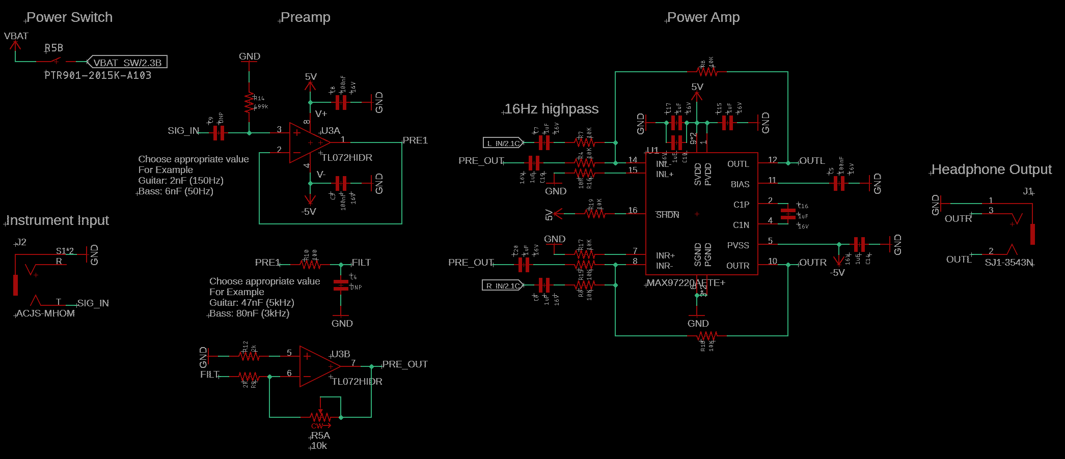
GavinI started designing Porter in August of 2022, when the combination of housemates and my penchant for late night solo jams nudged me to look for a way to practice more quietly. My tube amp didn't have a headphone output, and the one on my solid state amp didn't sound very good. All the options on the market plugged straight into the guitar and precluded the use of external effects, which I found very important not only for solo jams, but also for practicing any songs that require different effects at different points. I figured it would be fun to try making my own headphone amp as a side project.
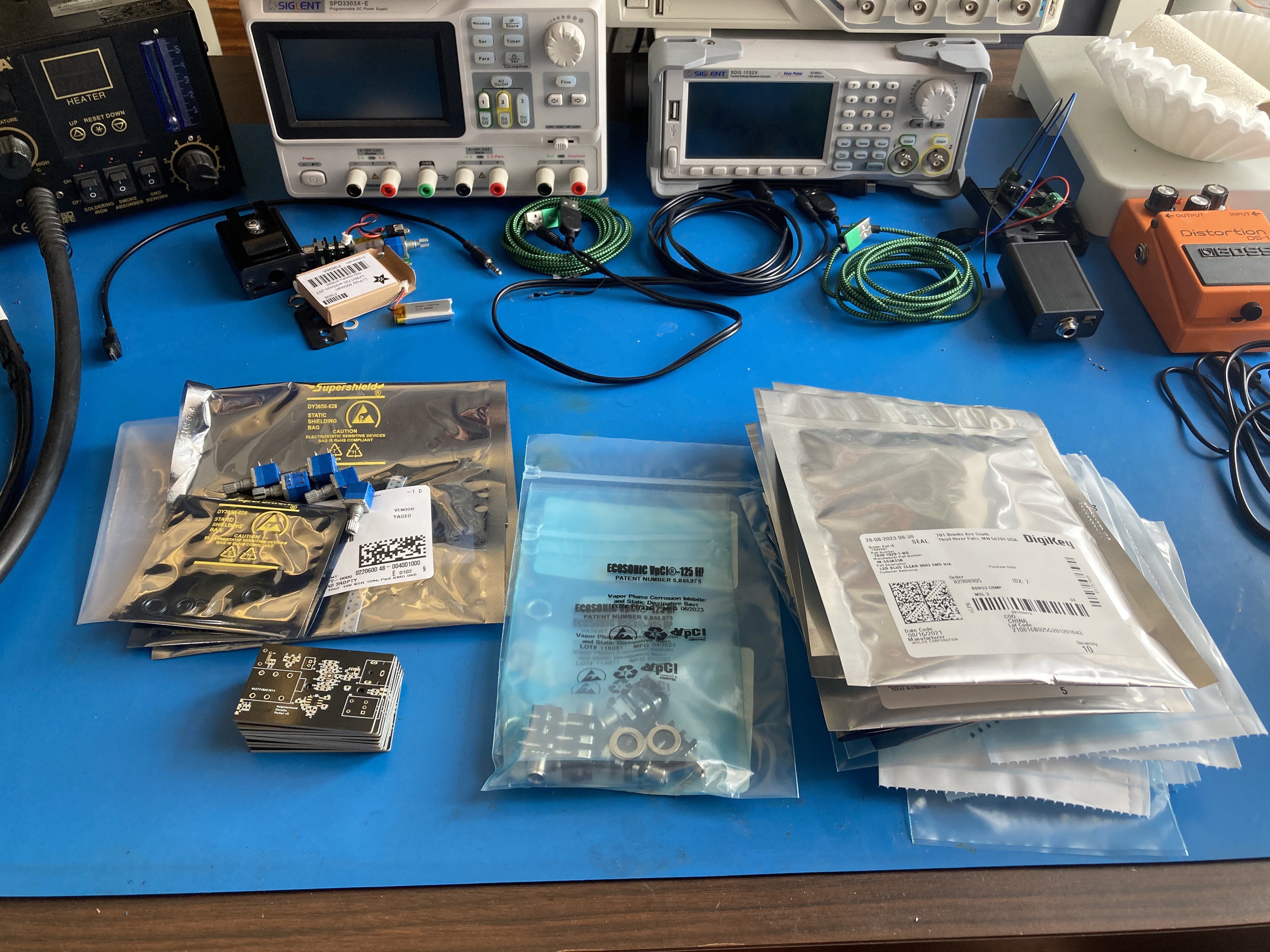
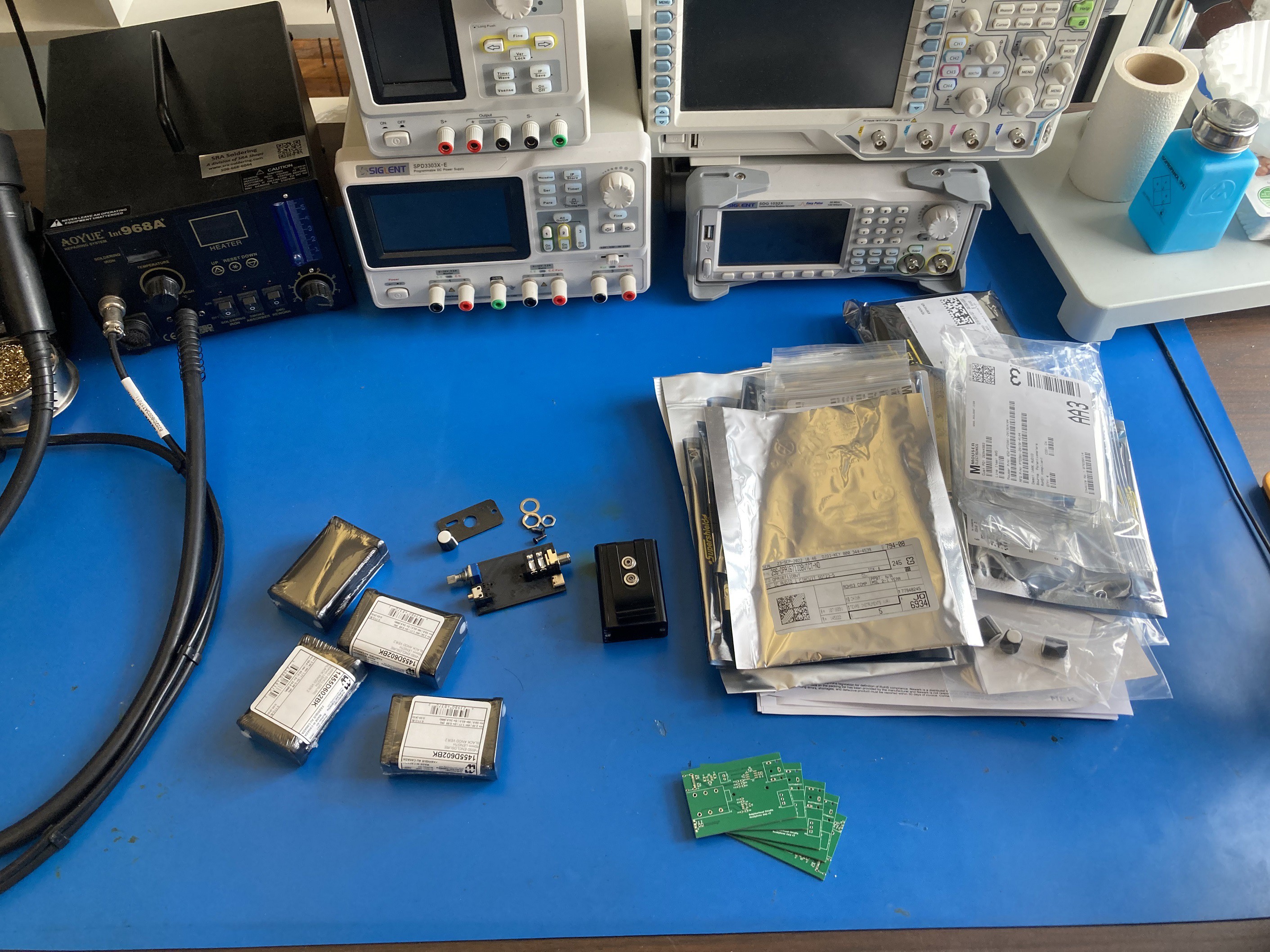
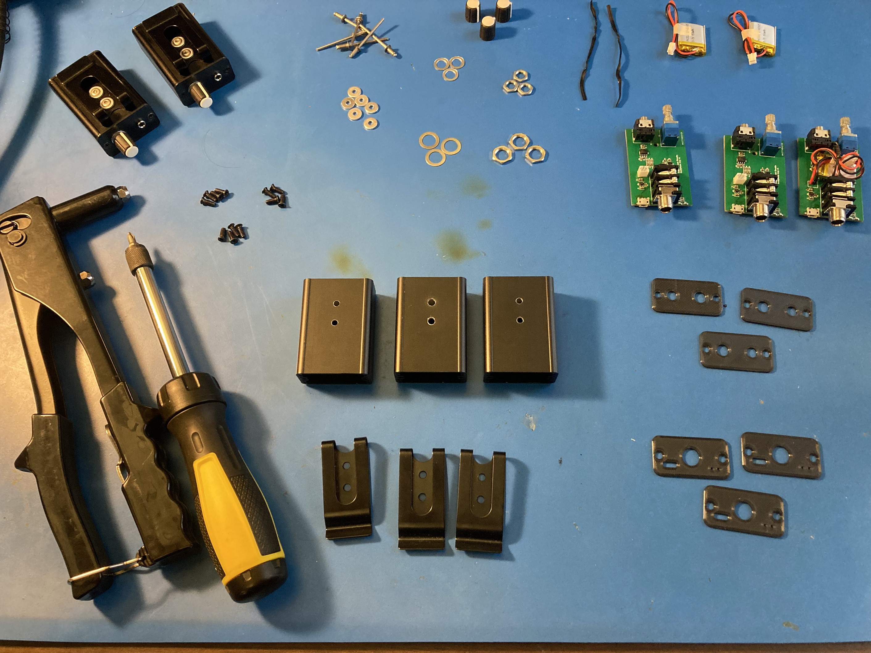
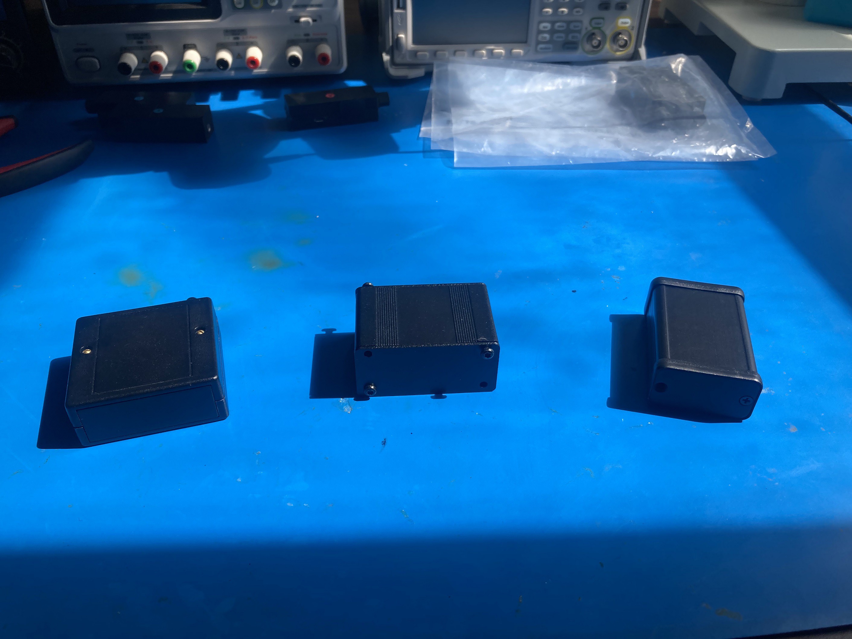
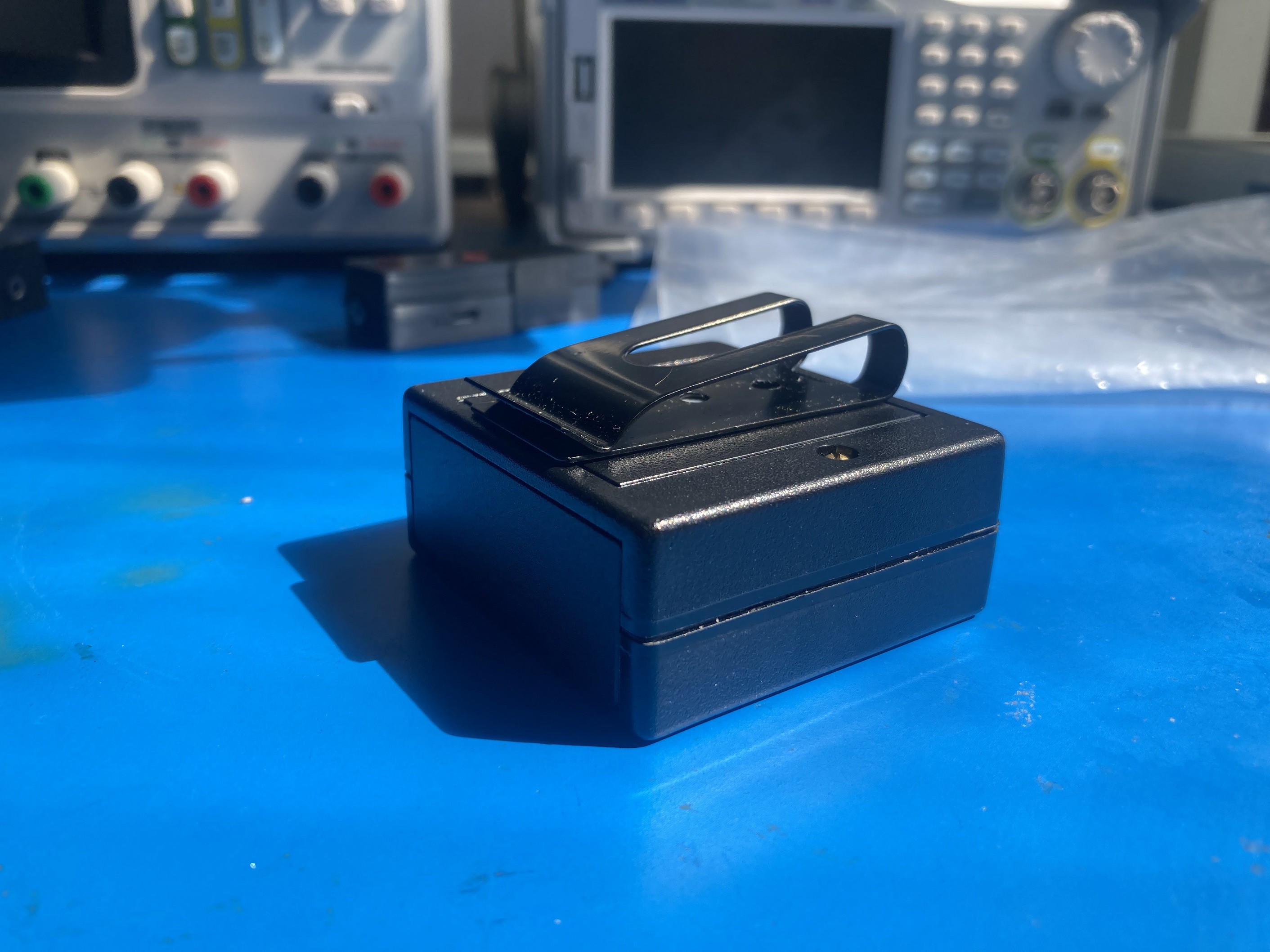
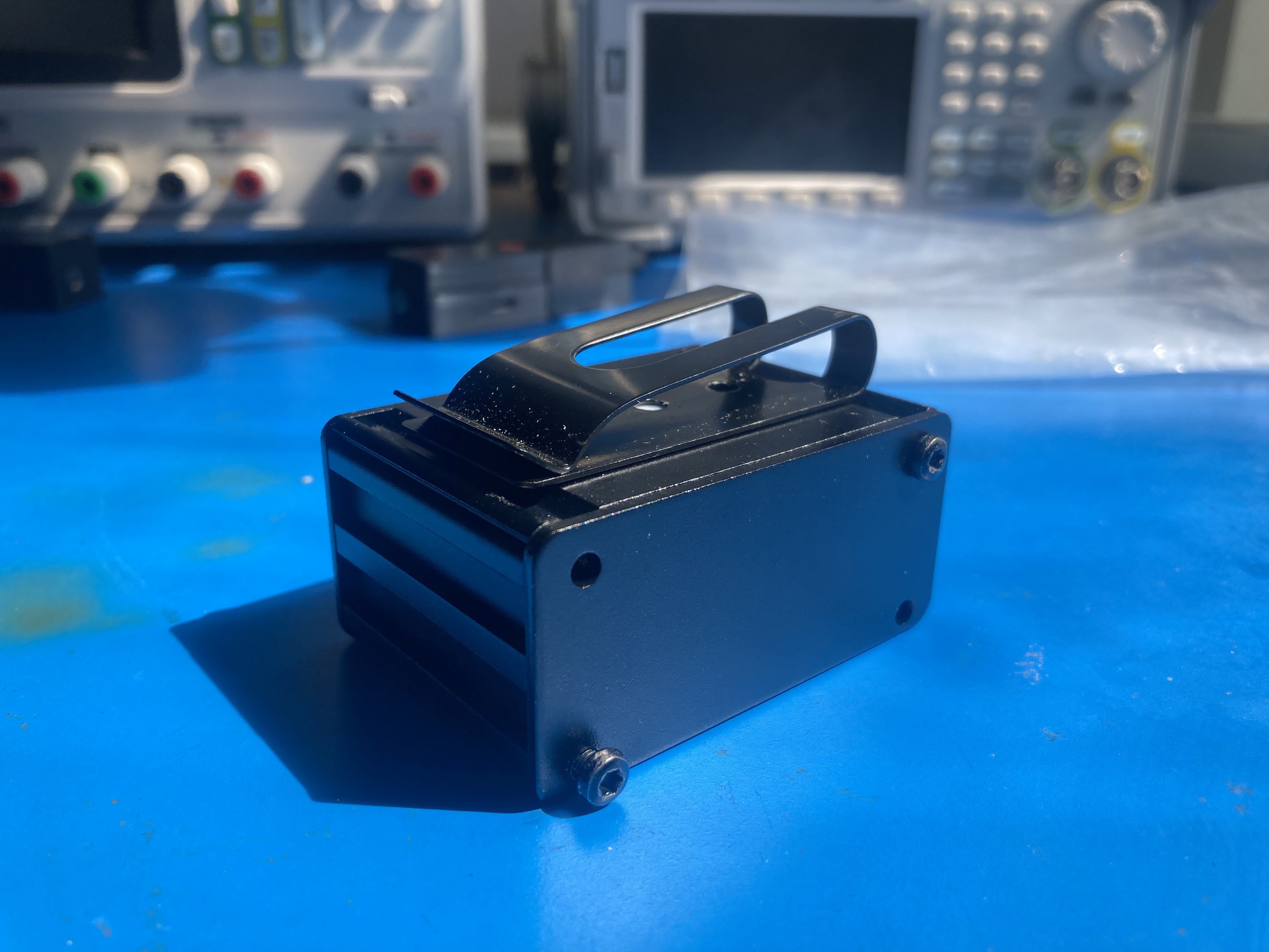
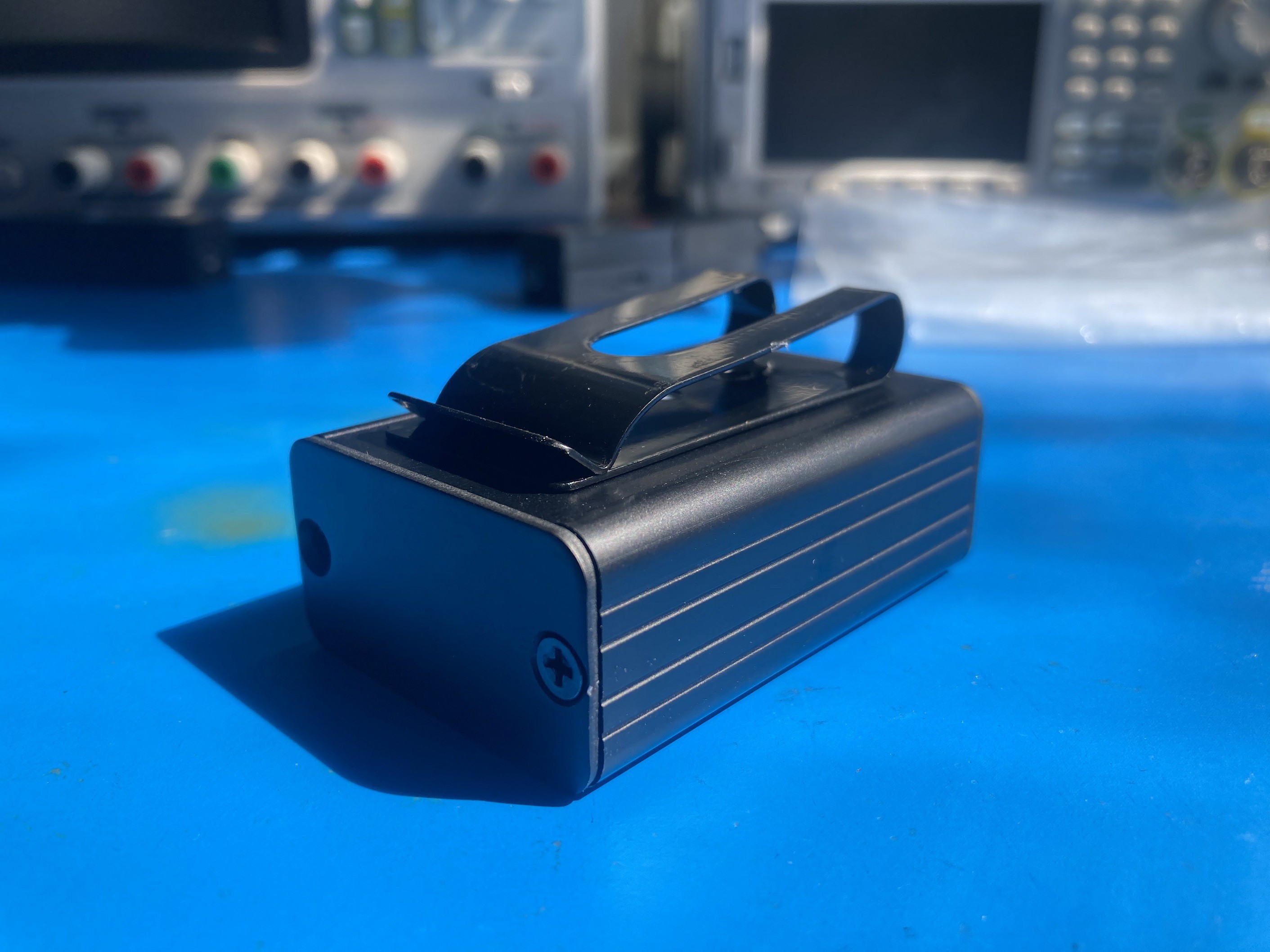
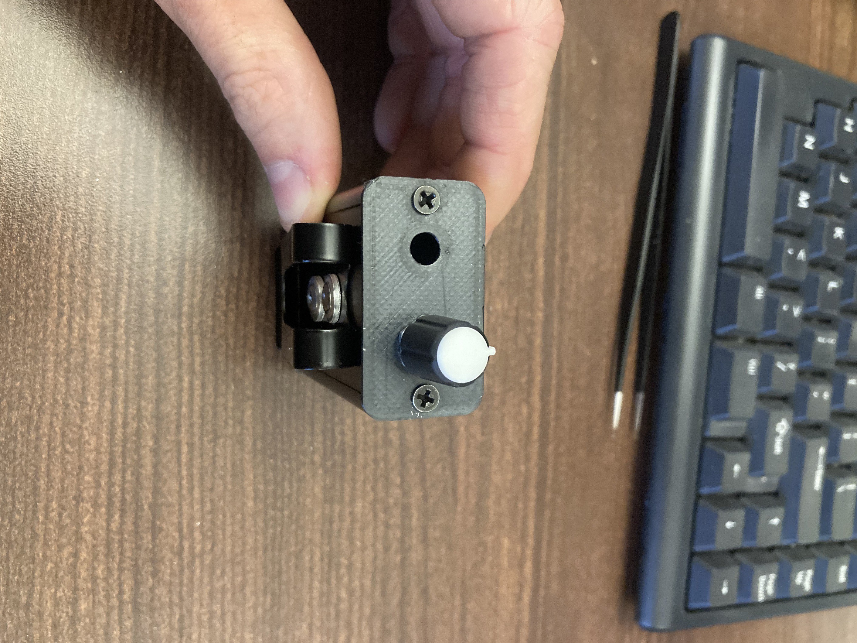
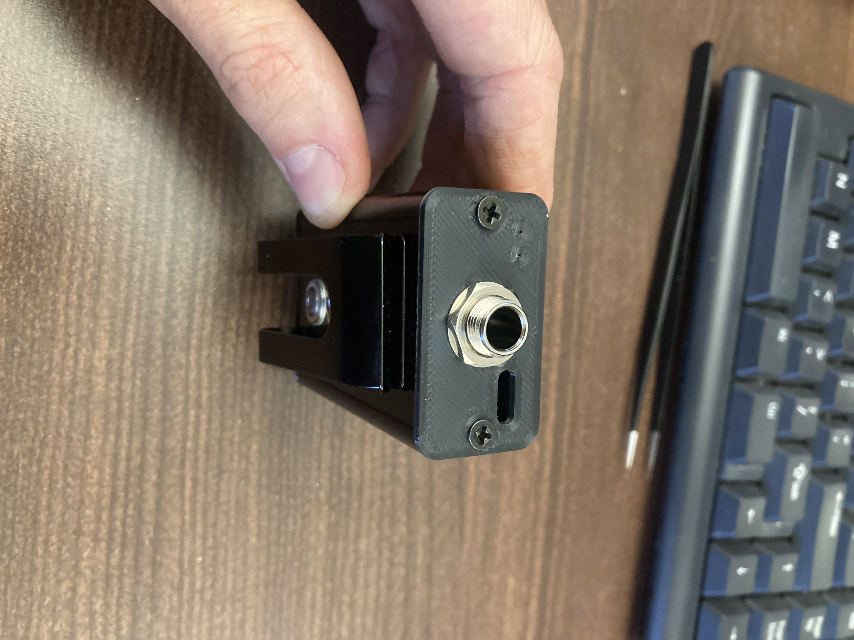
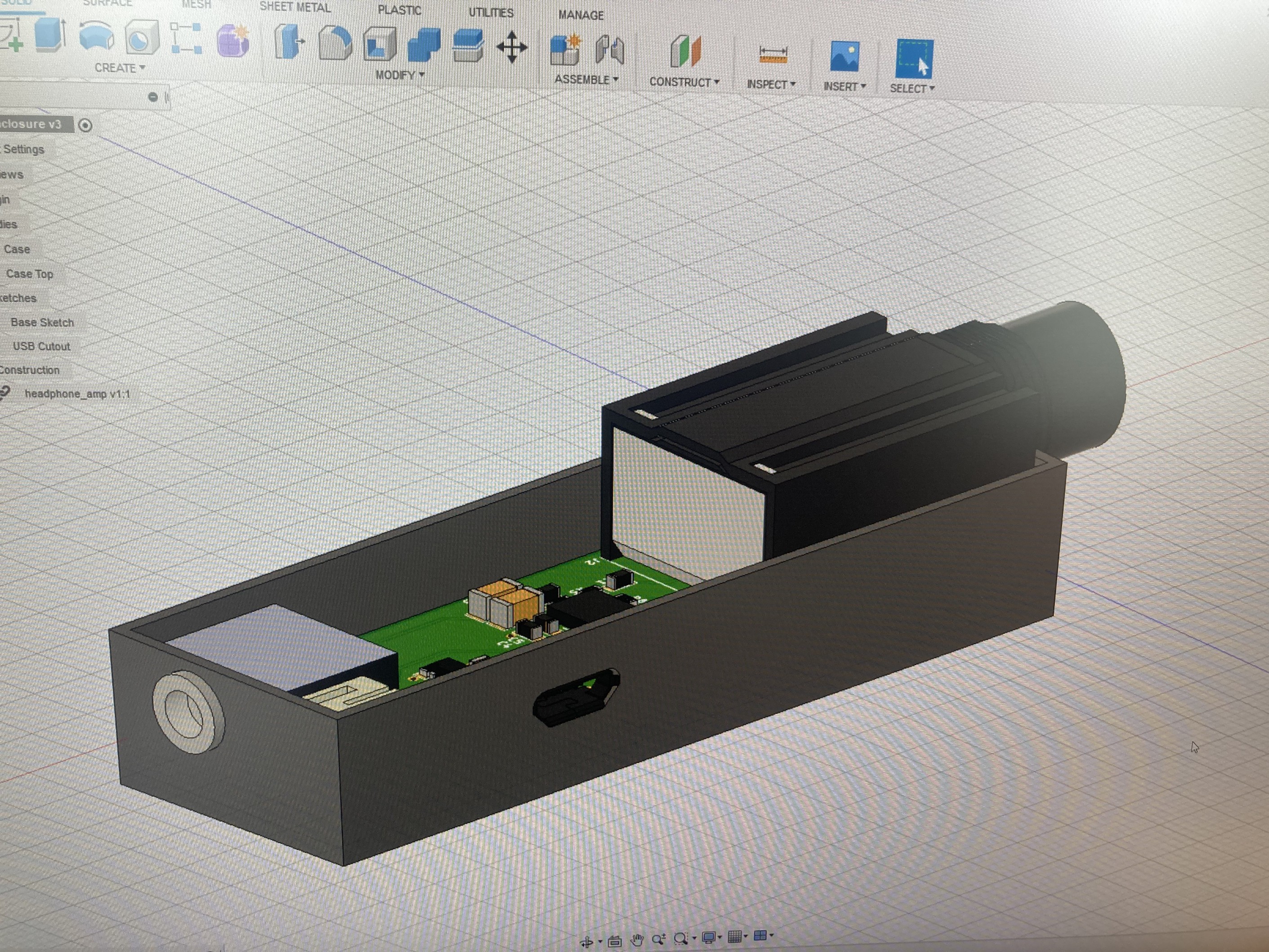
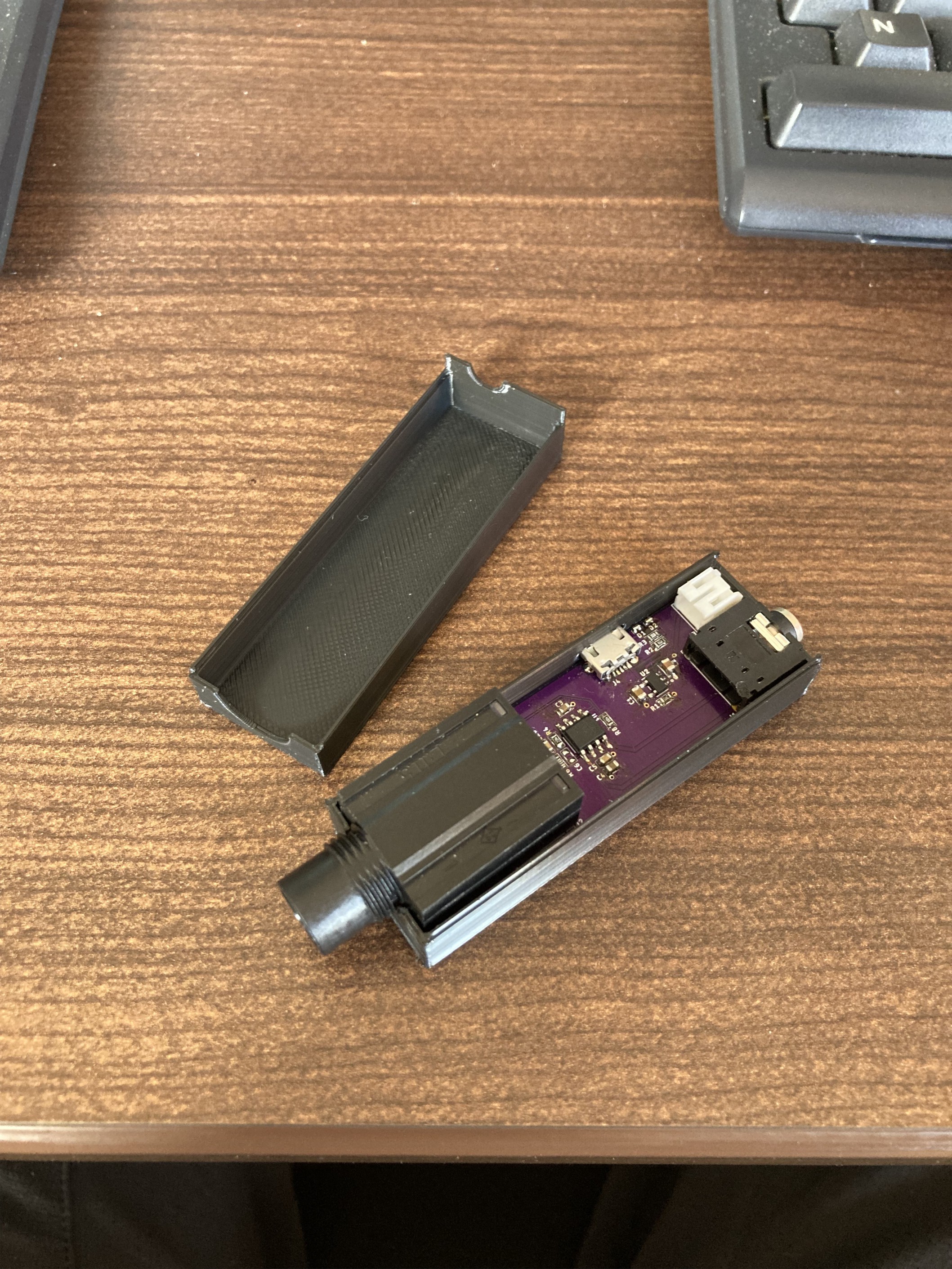
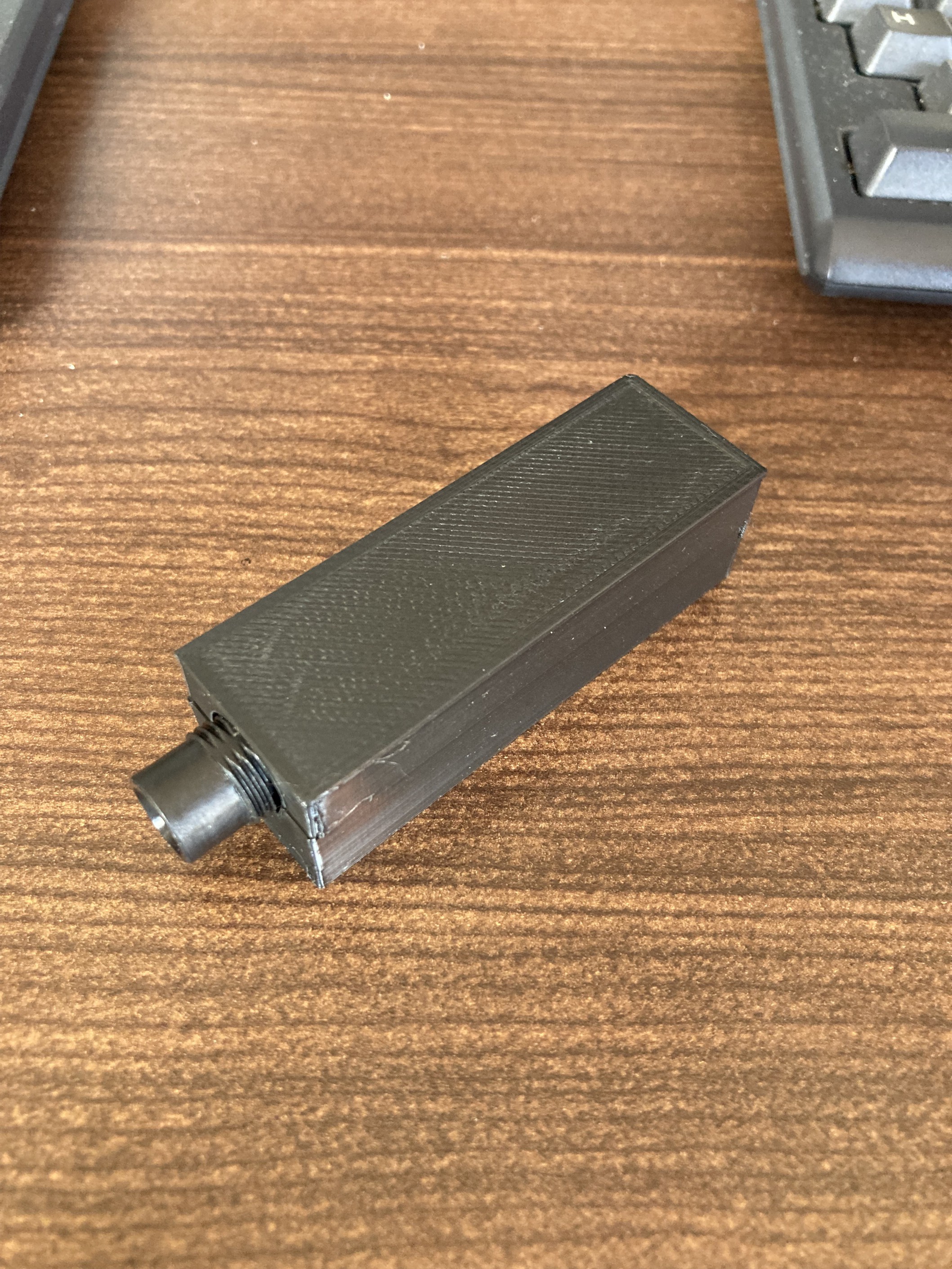
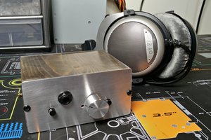
Back then, the project was just called "headphone_amp.sch" and was designed to be about the size of a pack of gum. I tried 3D printing my own case as a test project for my newly-acquired printer. It was a completely minimalist amp, with no controls, not even a power switch (it switched on when you plugged a cable into it, a trick commonly used on pedals and guitars with active outputs). The design has evolved over the 6 revisions and almost 2 years since I started, adding features that I realized were necessary to really be effective as a practice tool. The form factor grew to the size of a beeper (remember those?), which conveniently aligned with an off-the-shelf Hammond enclosure.
I am hoping to make Porter available on Crowd Supply in the near future. In the interim, I thought it might be of interest to document its evolution over the years. Here are the most current features and specs:
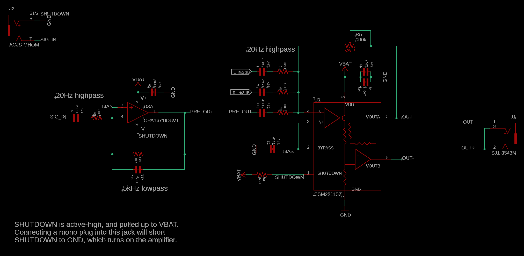
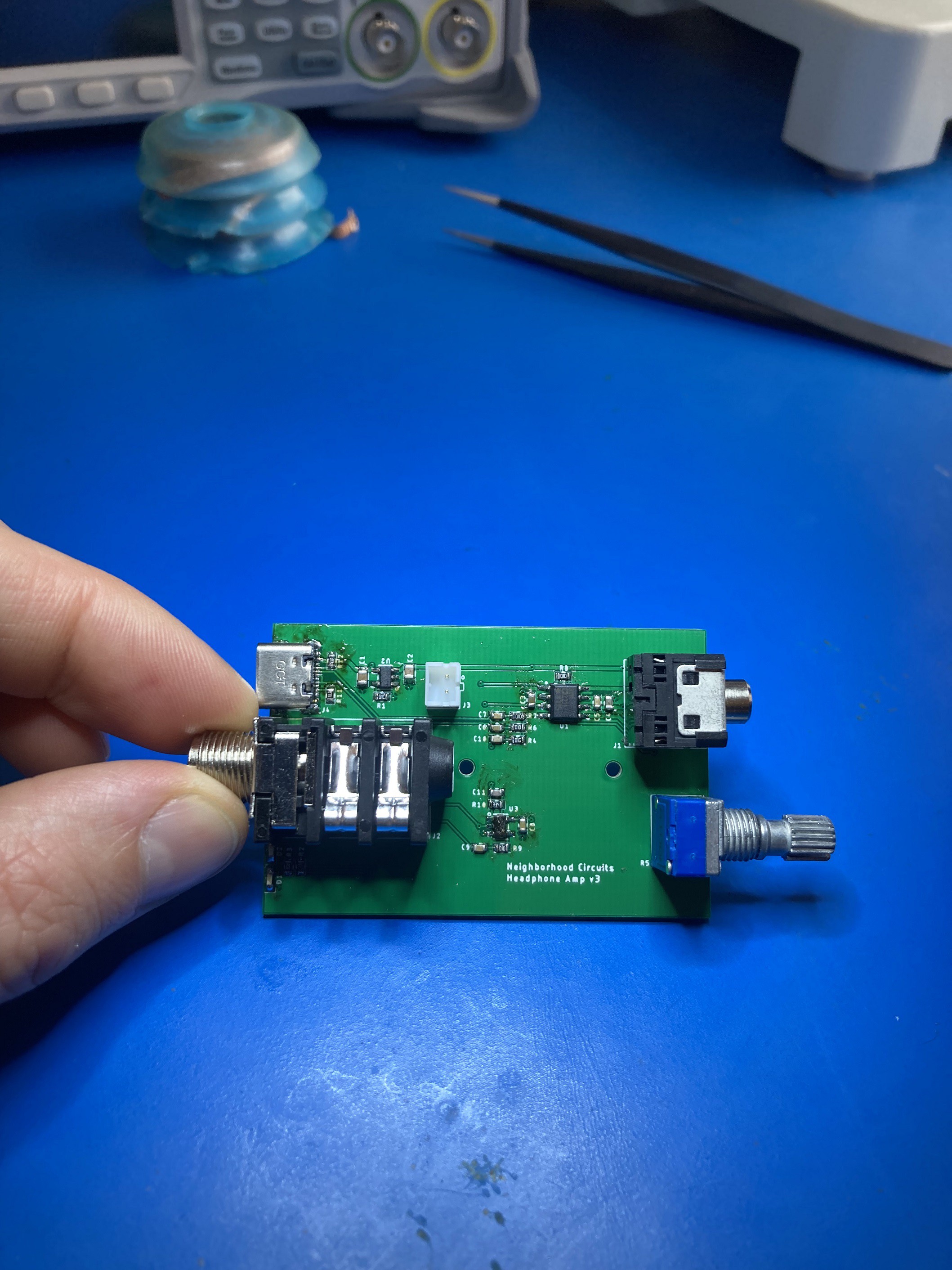
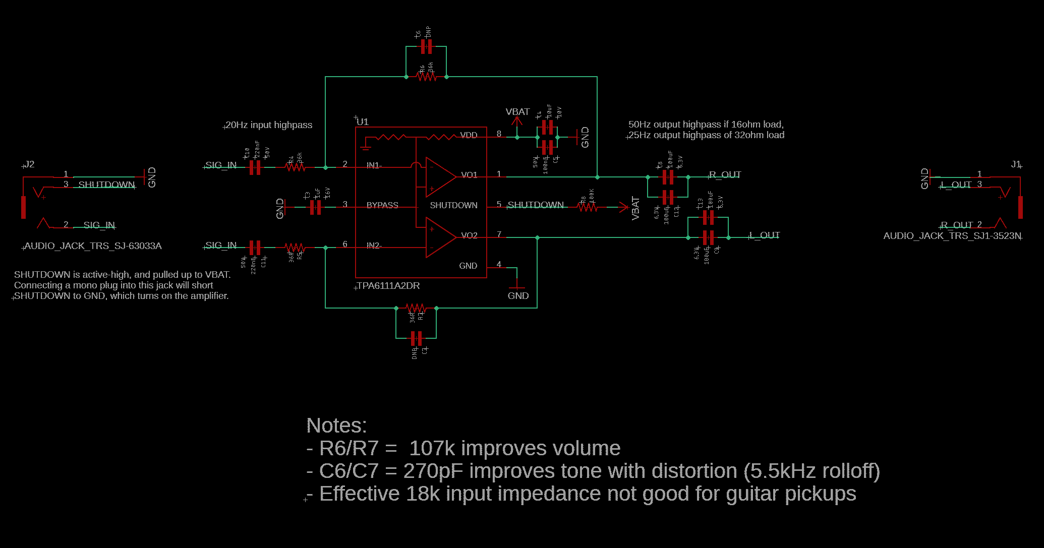
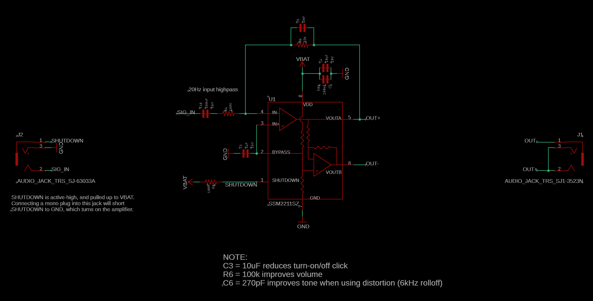
- Inputs: 1/4-inch jack, micro USB (for charging or 1/8-inch line-in with included adapter)
- Output: 1/8-inch TRS headphone jack
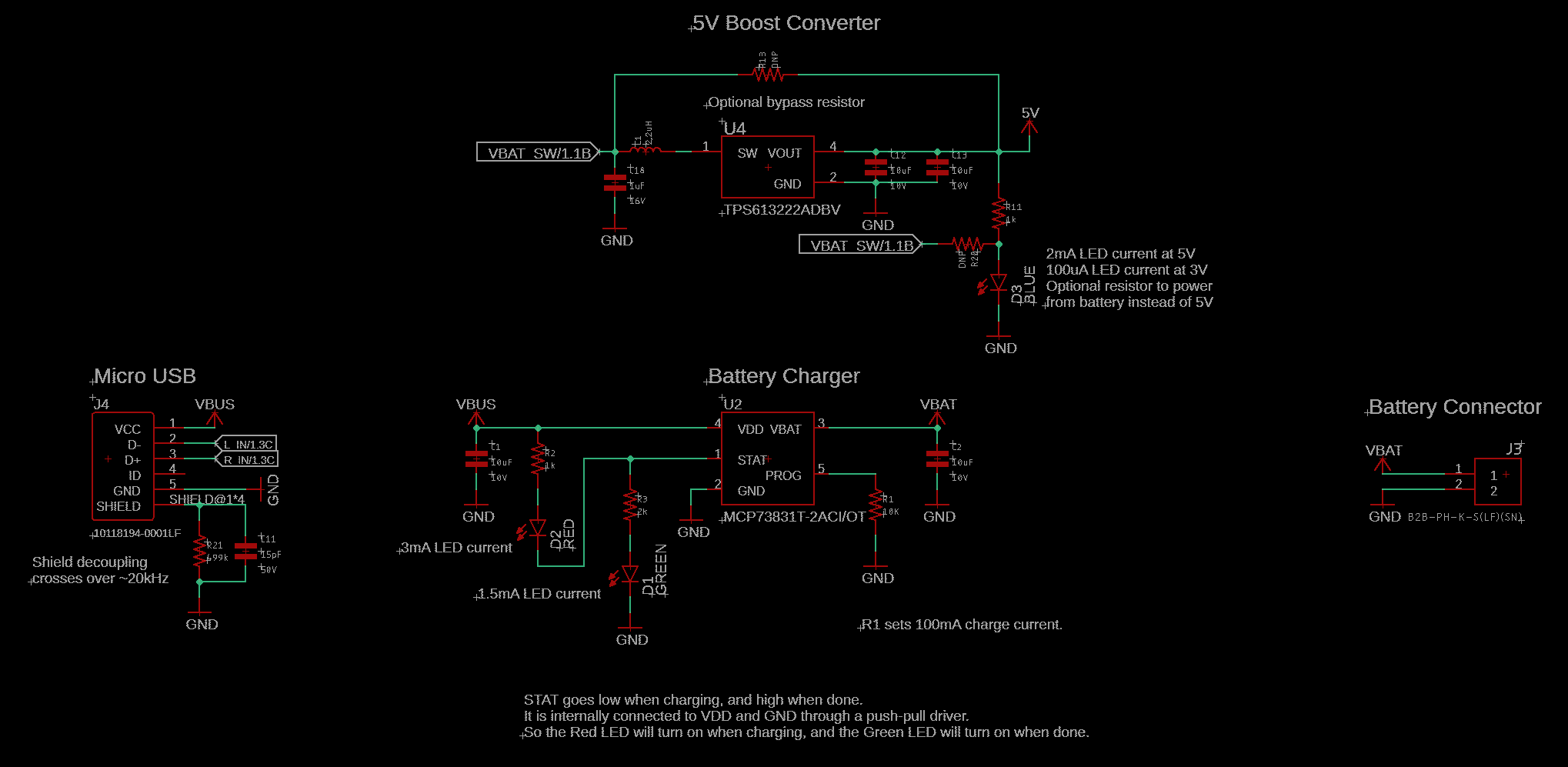
- Indicators: Status LED for power (blue), charging (red), and charge complete (green)
- Controls: Volume potentiometer with integrated on/off, bass/guitar selector switch
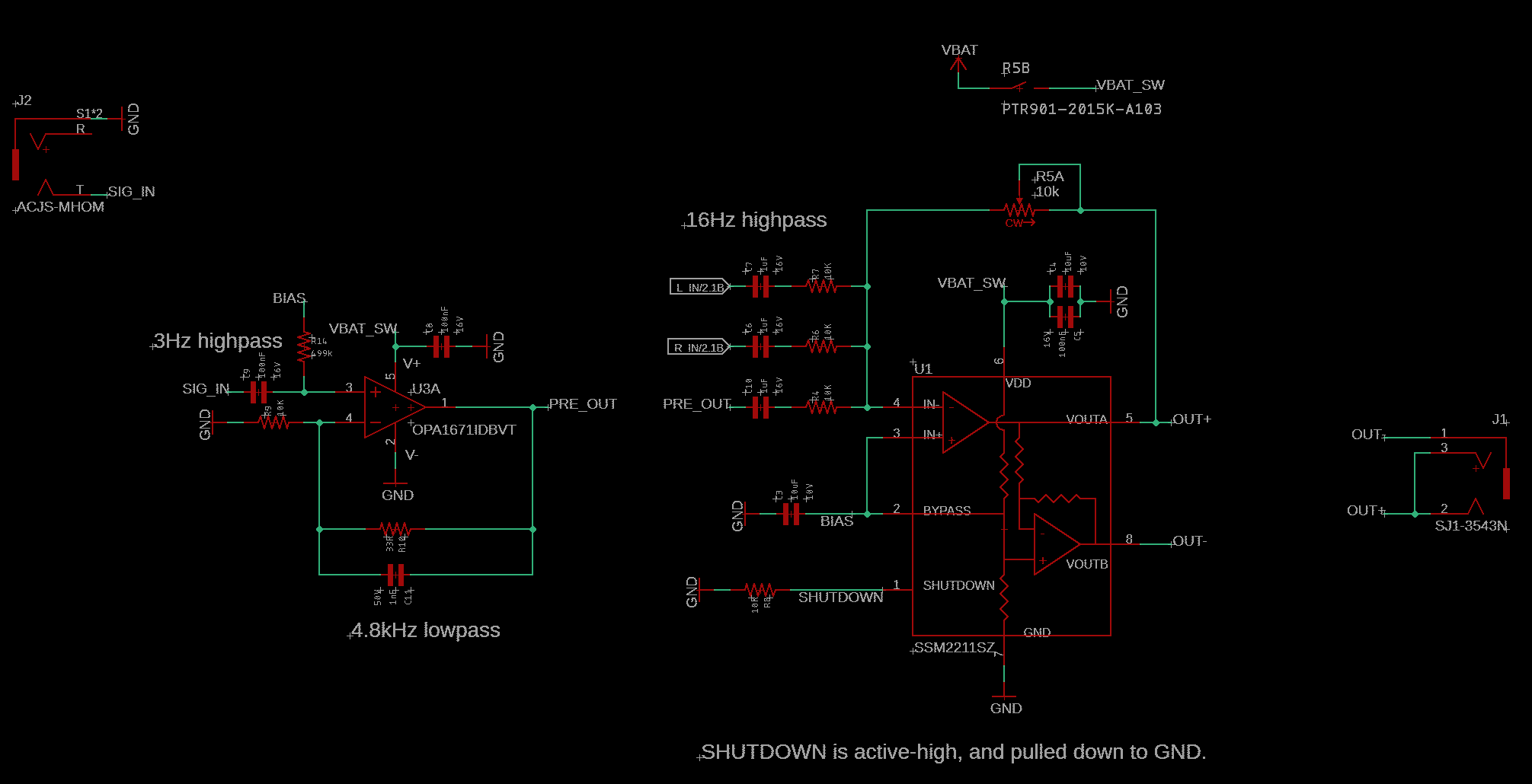
- Input impedance: 500 kohms guitar mode, 1 Mohm bass mode
- THD+N: 0.003% at 60 mW into 16 ohms Power output: 110 mW into 16 ohms, 125 mW into 32 ohms
- Frequency response: 55Hz-6.2 kHz bass mode, 95Hz-6.5 kHz guitar mode
- Battery: 300 mAh LiPo with JST connector (~15 hour runtime, 2 hour charge time)
- Enclosure: Anodized aluminum with belt clip


 Alan Cyr
 onFile
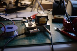
 Kris Slyka