 Arnov Sharma
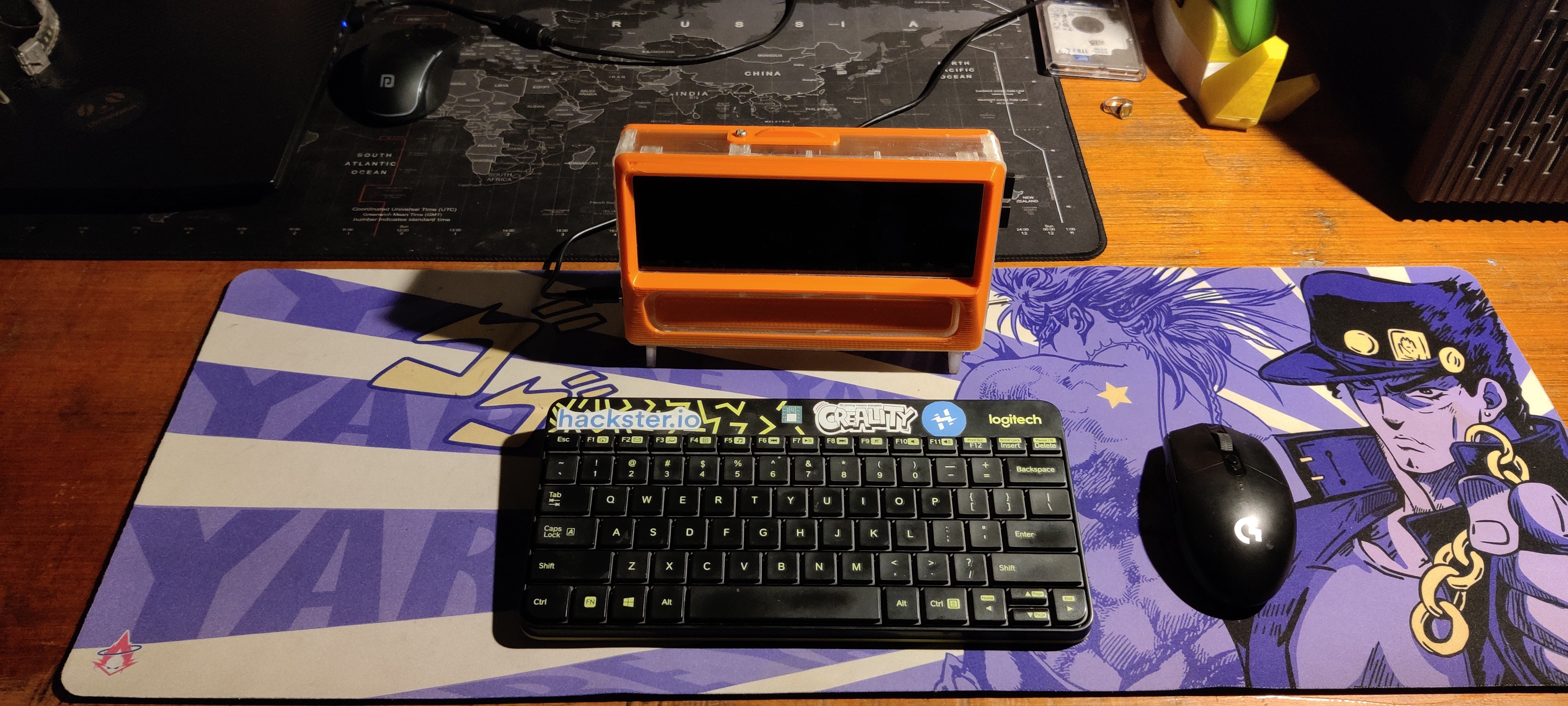
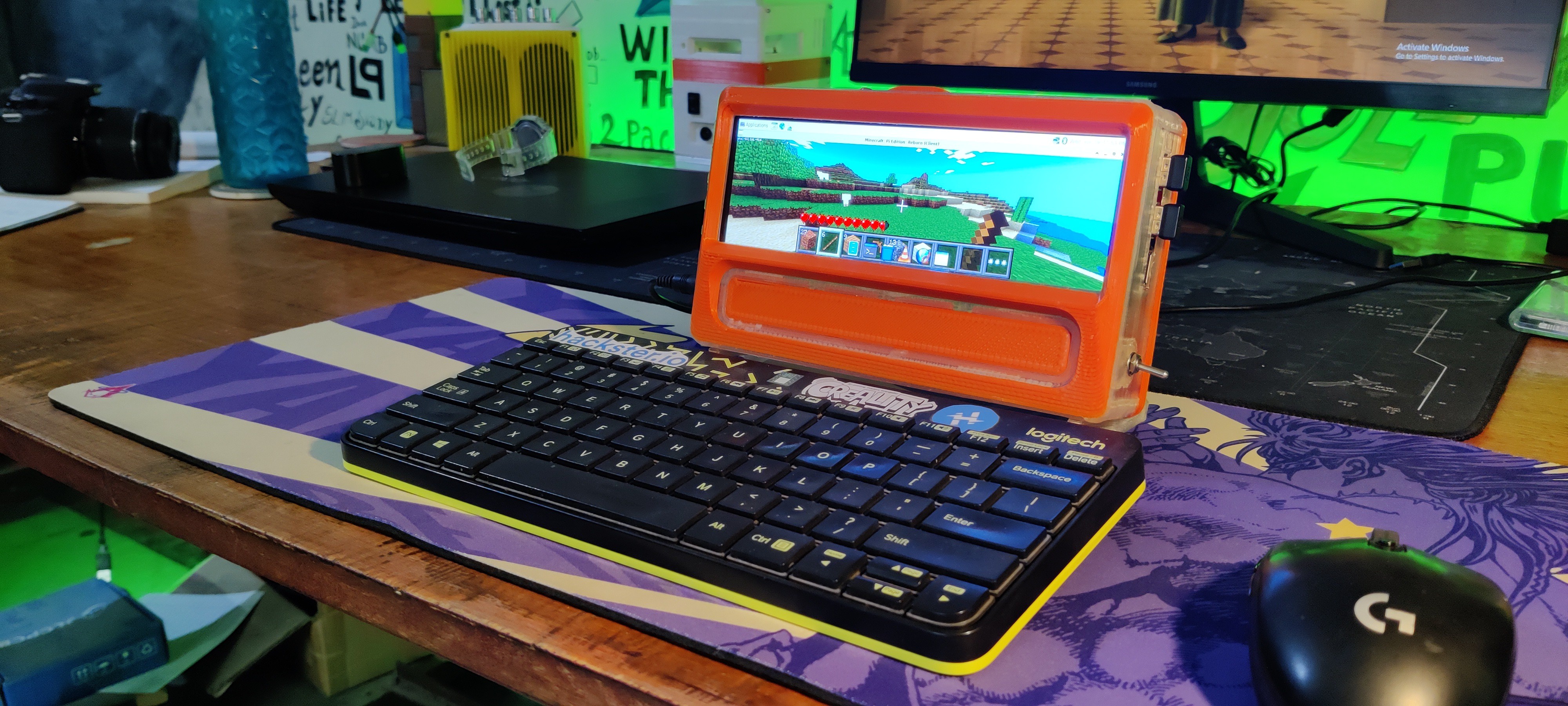
This configuration is powerful and capable of running everything we throw at it thanks to the Pi4; for instance, Minecraft Pi Edition Modded is running on this setup.
Installing Pi-apps will allow you to add a ton of programs to this setup, such as games like DOOM and emulators like PPSSPP. We even personalized our Pi to look like a Mac by using a custom Mac OS theme.
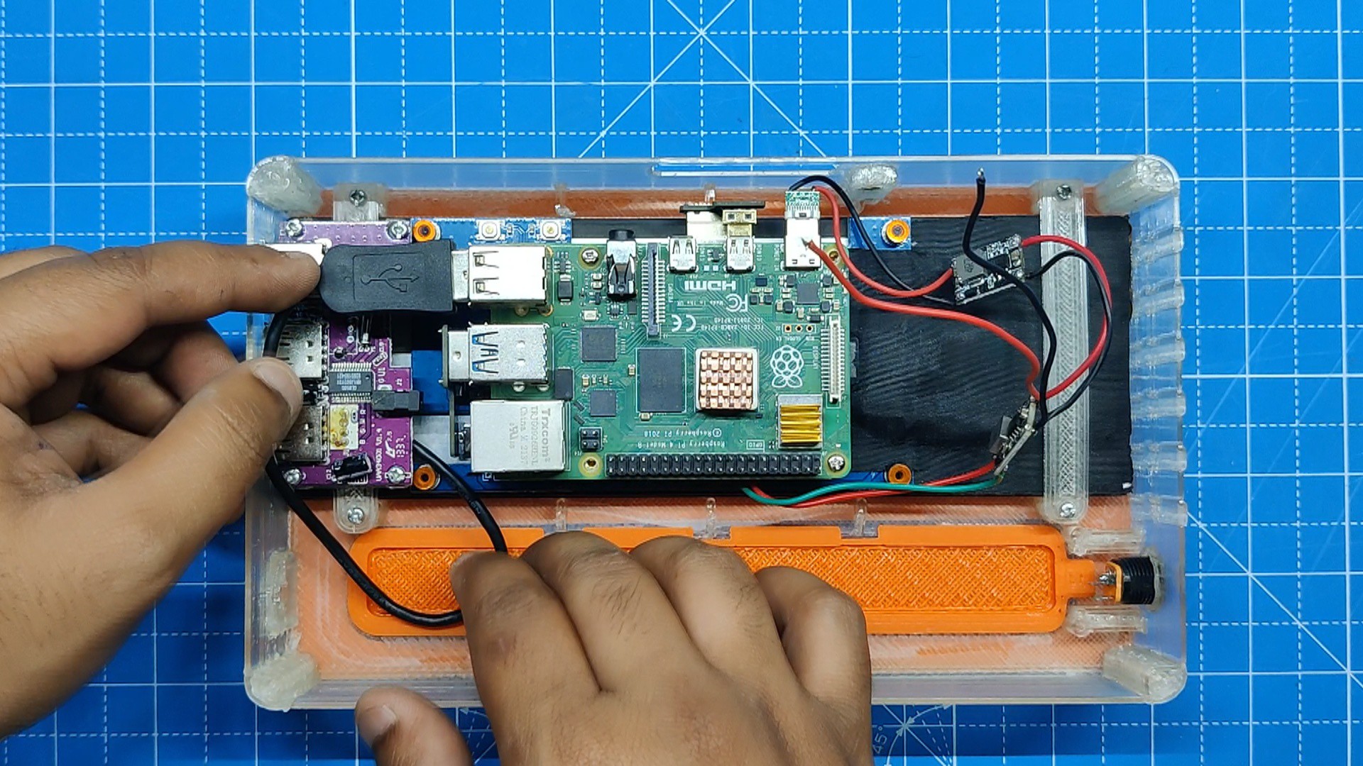
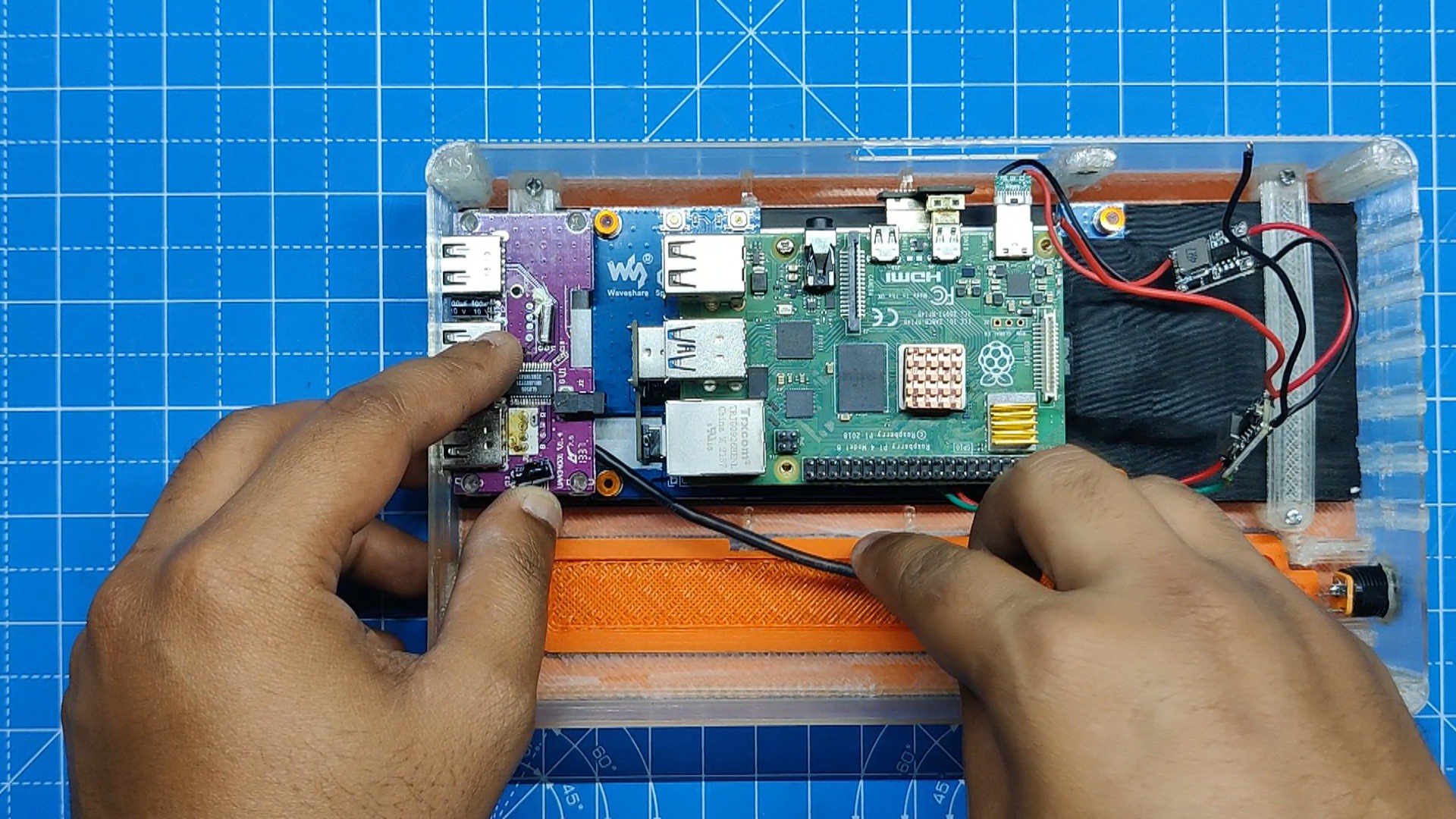
In order to expand the Pi4's IO ports, we have also added a USB hub to this device.
Additionally, the display we're using is a touch screen.
3D Design

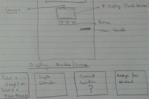
In order to model the 7.9-inch display, we first had to build the body of the model. To do this, we measured the display manually and created the model.
Then, as the display has PCB standoffs placed on it especially for mounting the Raspberry Pi, the Raspberry Pi 4 Model was imported into the design and placed on the back of the display.
whole model was then designed around the screen.
The design was divided into two main parts: the Main Body and the Back lid.
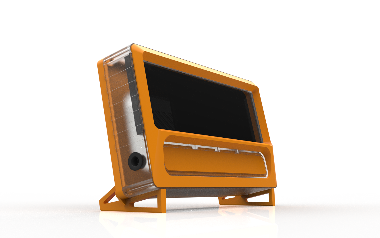
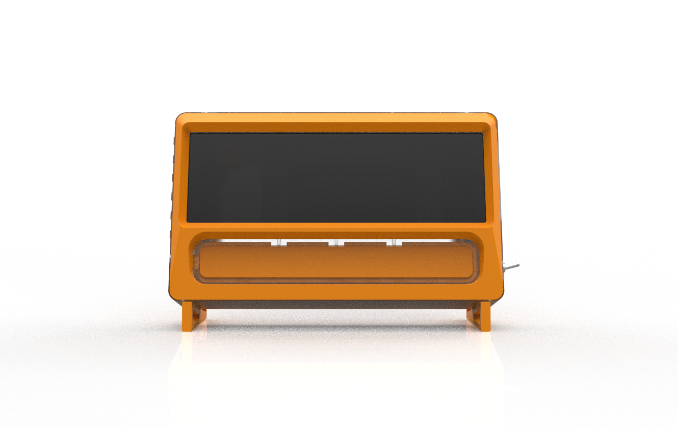
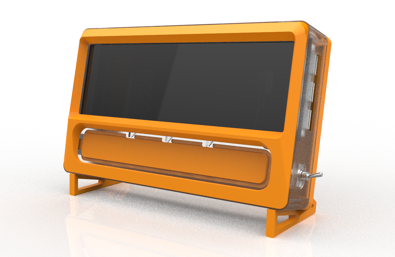
The main body holds the screen and Pi arrangement from the inside; The exterior features a curved screen front cover part that we made after the front appearances of vintage CRT monitors;
We modeled the front face by taking influence from CRT monitors, which shared similar designs. To enable us to print the main body and the front face using various colors of filament, we separated the two pieces. This will provide contrast to the model and improve its aesthetic appeal.
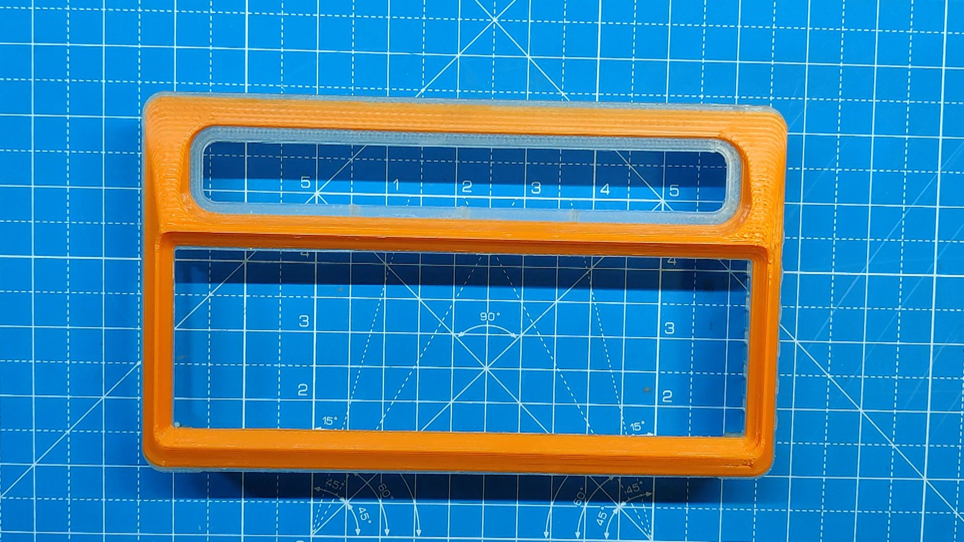
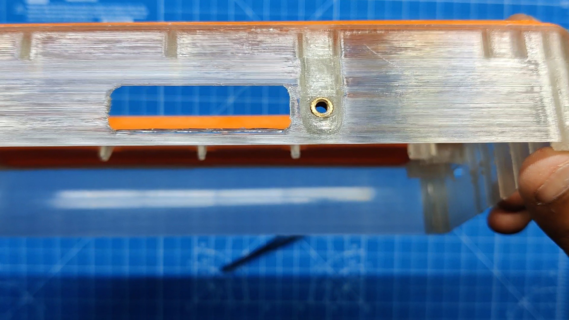
To enhance the visual appeal, we modeled a second part for the main body and created an opening that is filled with an orange-printed part. We named the following component the slot part.
I have combined two distinct pieces with two color tones across the model to create a single assembly, to enhance the visual appeal and design of the project.
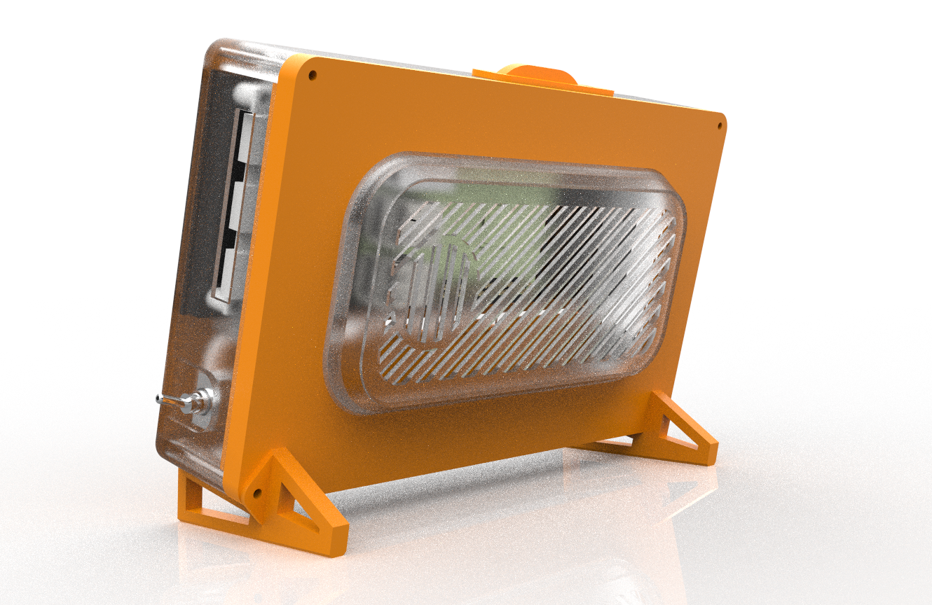
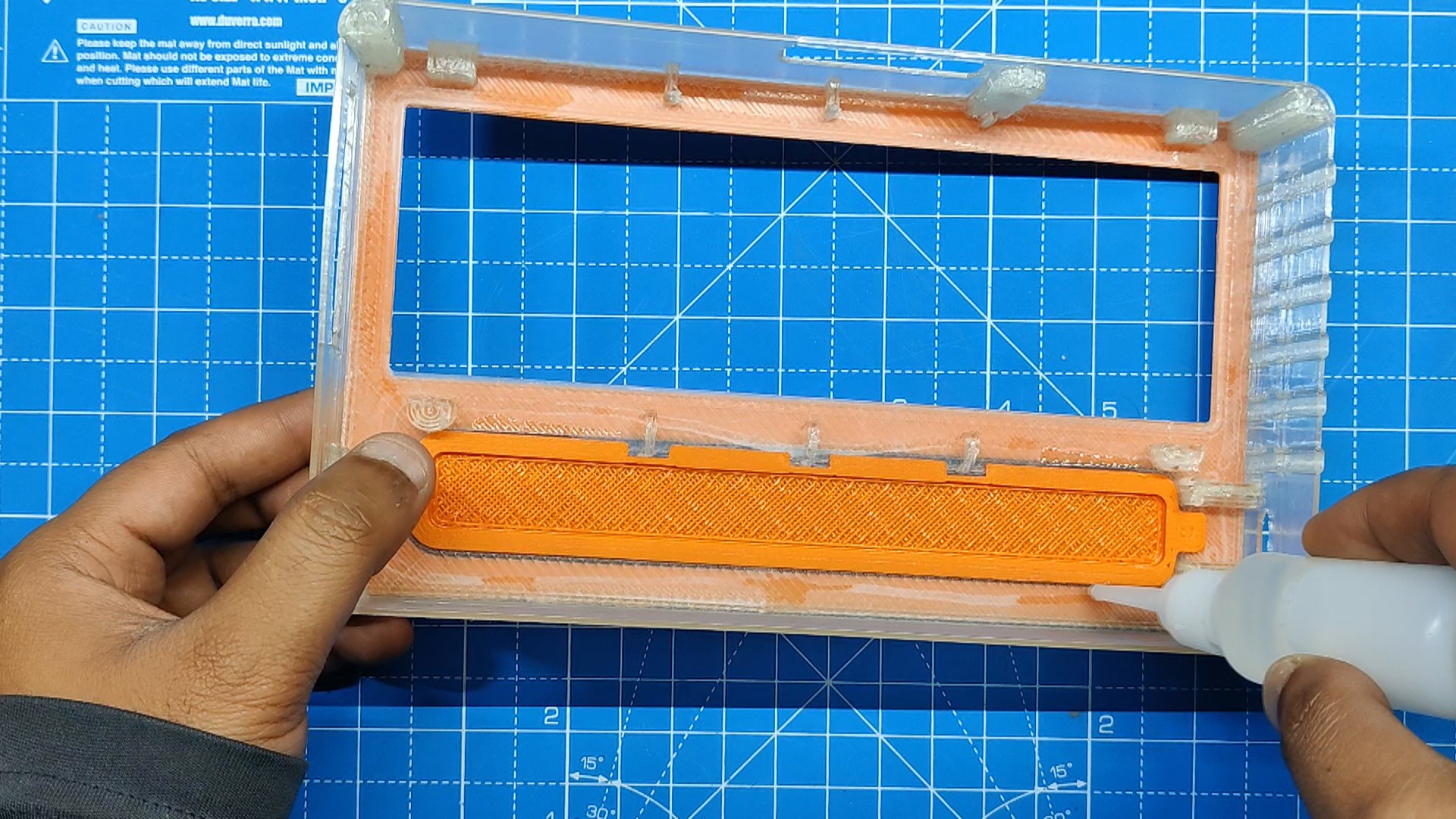
The Base Lid part is modeled with a large opening in the middle. In this opening, we will add a grill for air ventilation, This grill part is printed from transparent PLA, and the lid itself is printed with orange PLA.
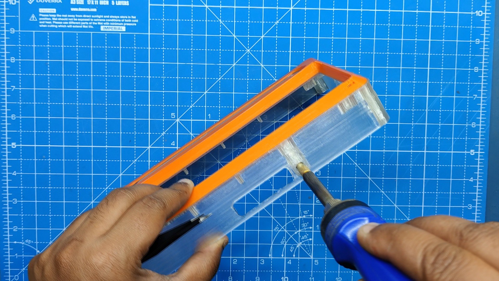
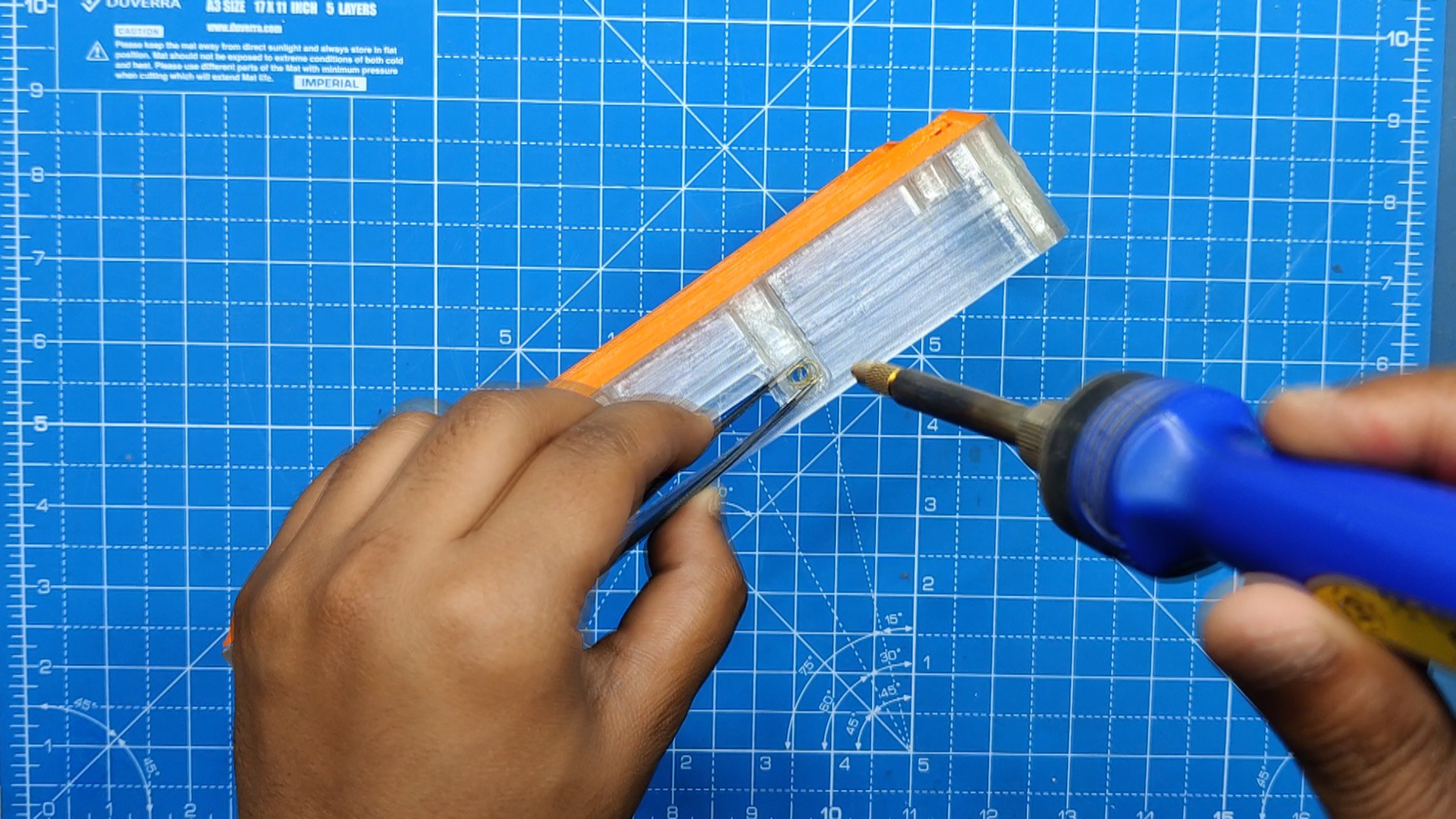
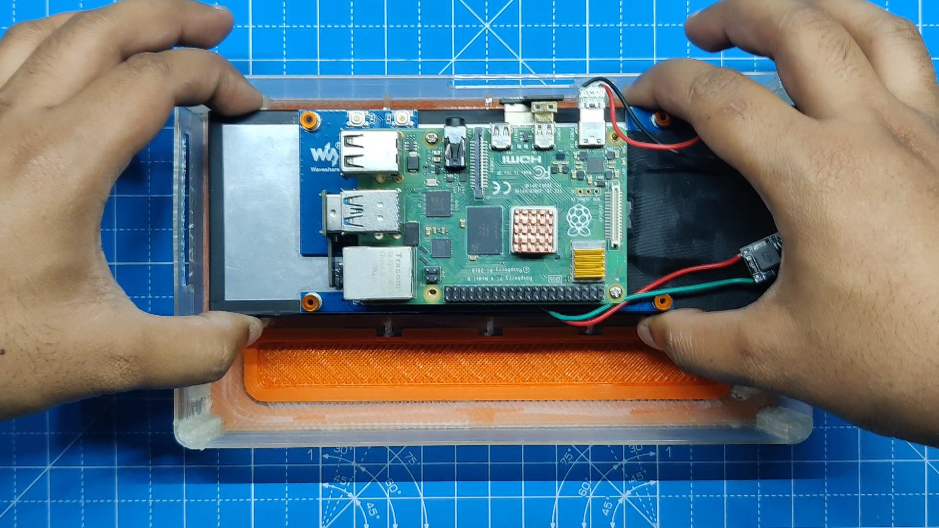
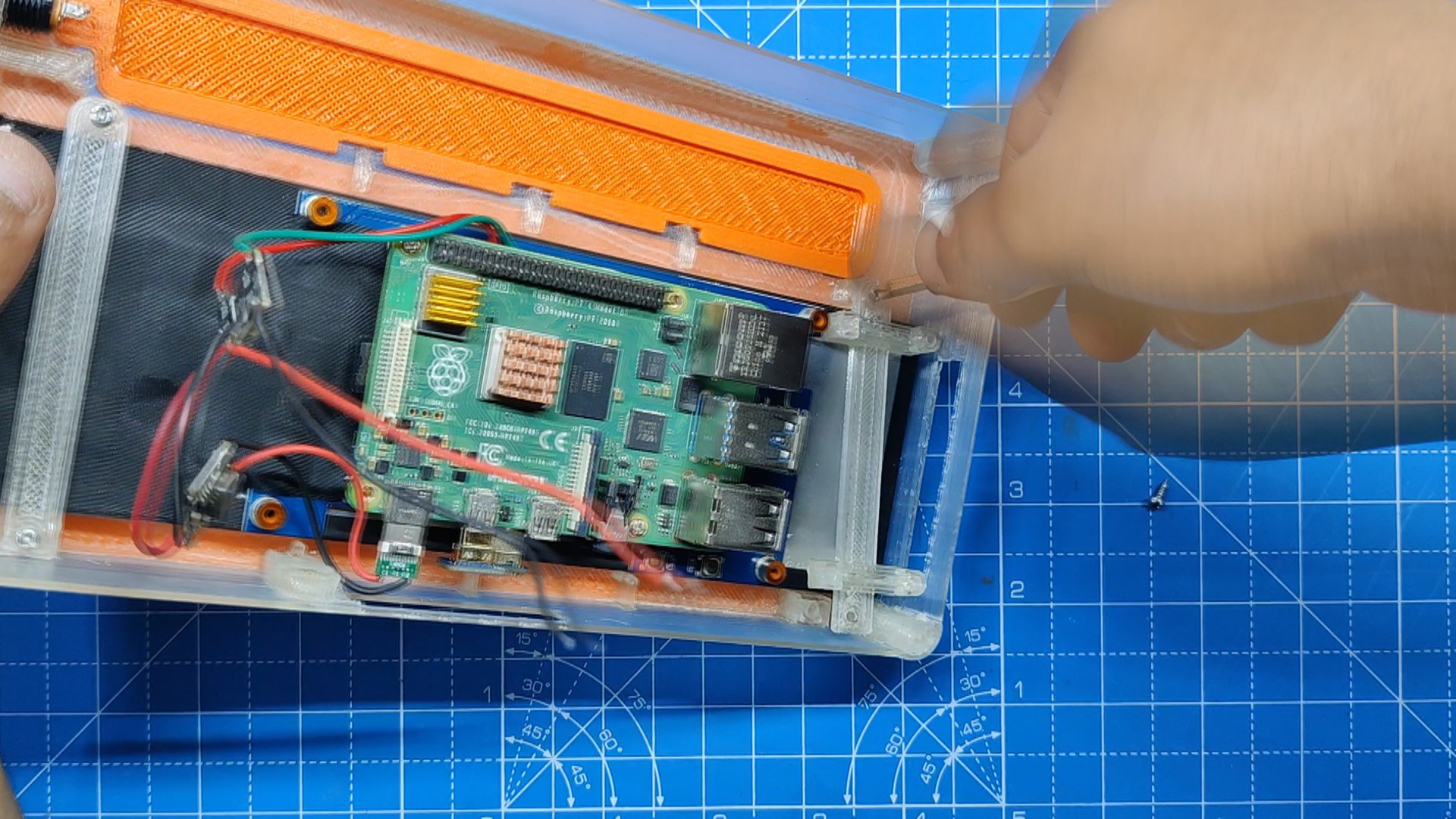
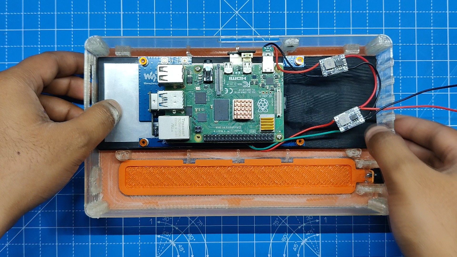
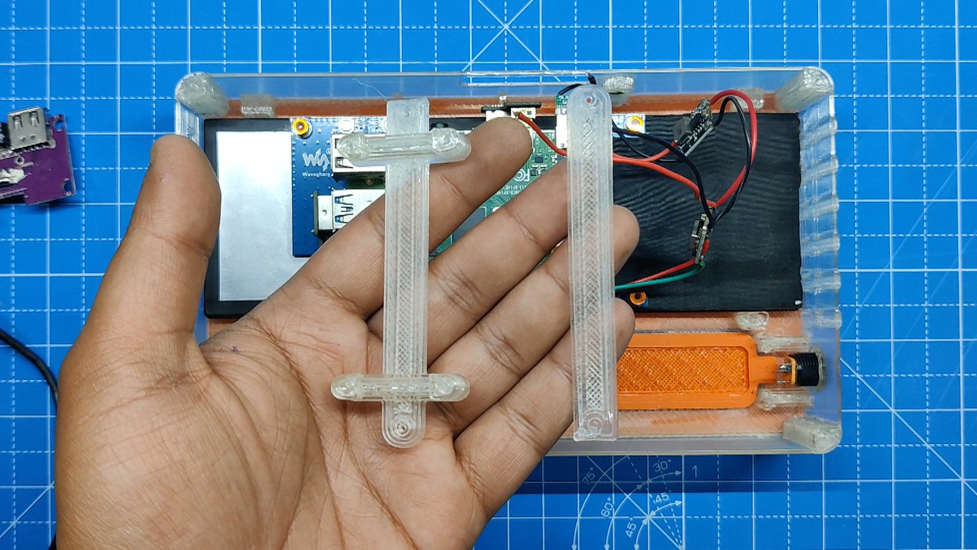
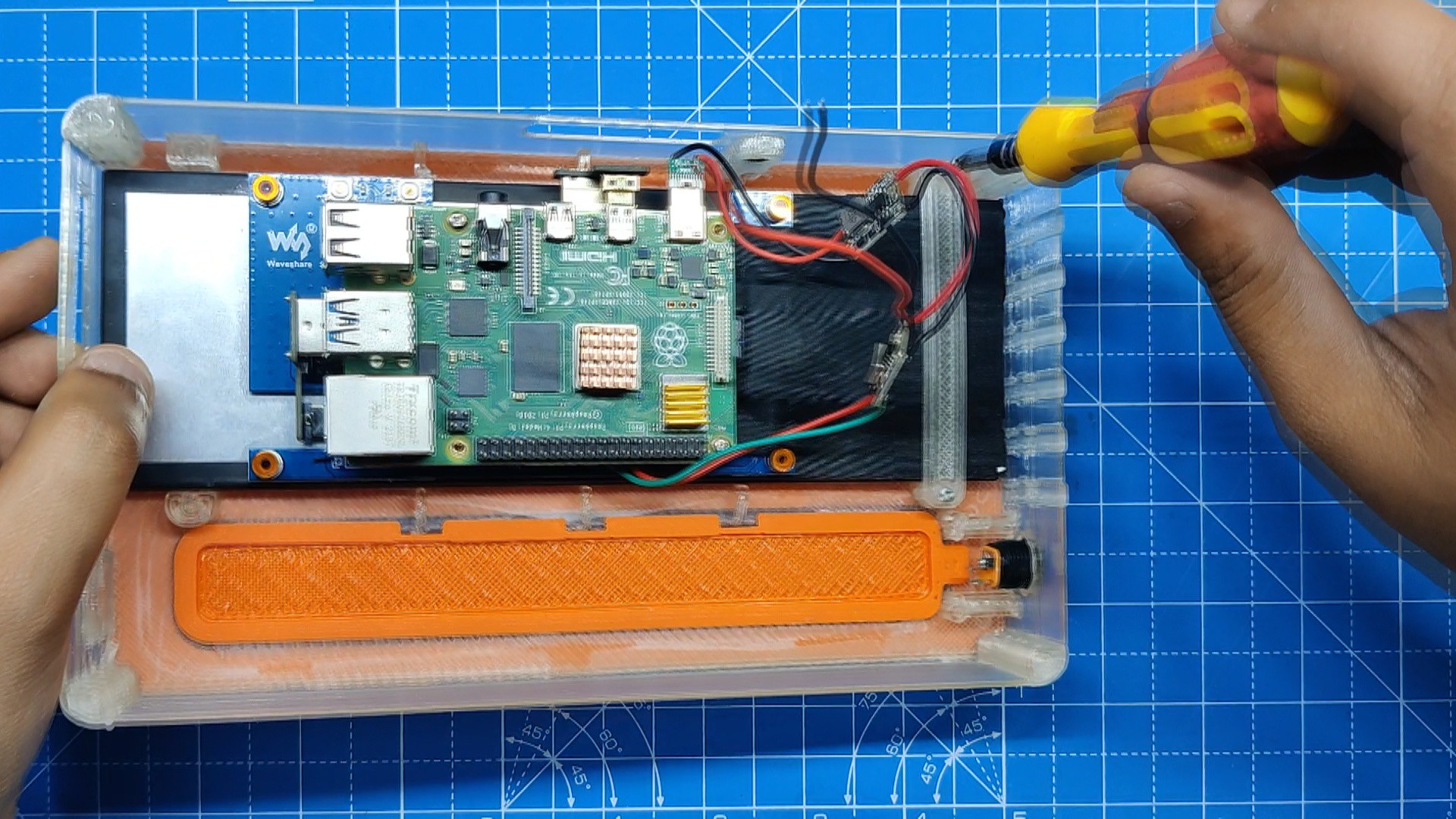
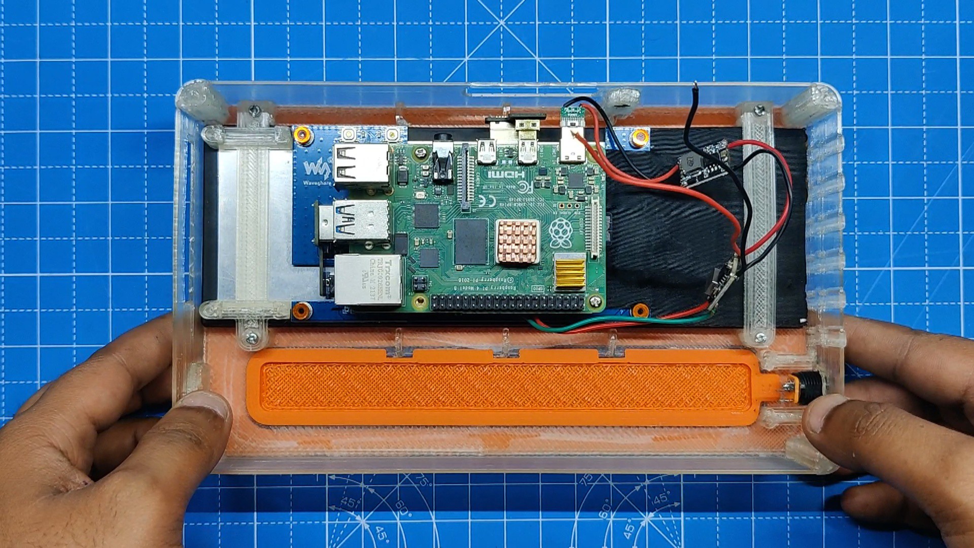
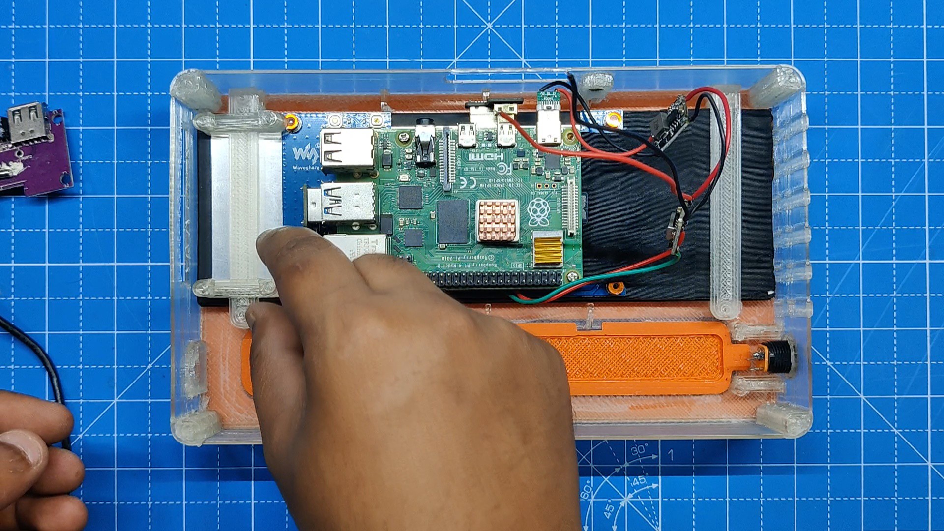
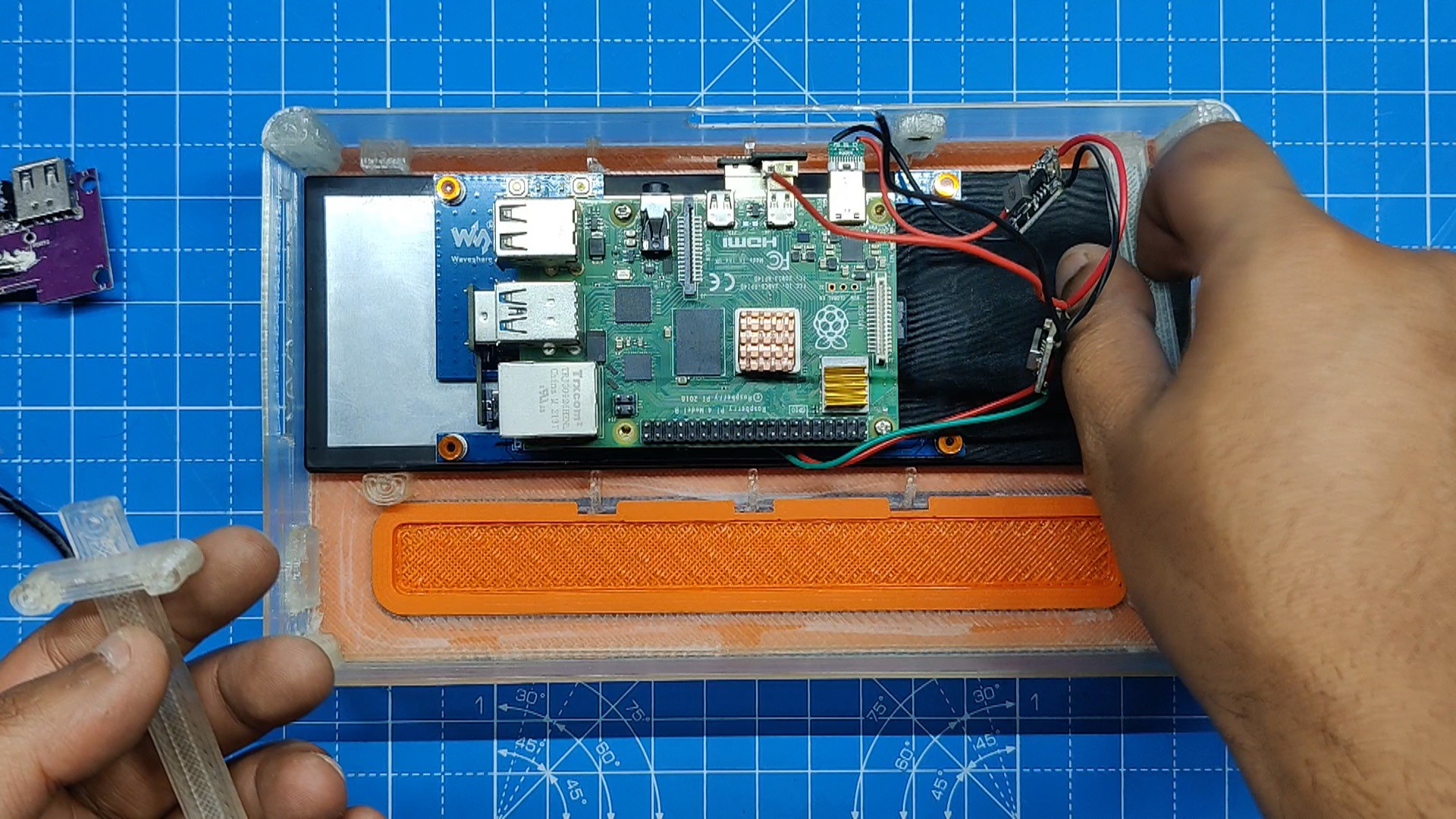
We have modeled two screen holders inside the main body that, when installed, will hold the screen and Pi assembly in place.
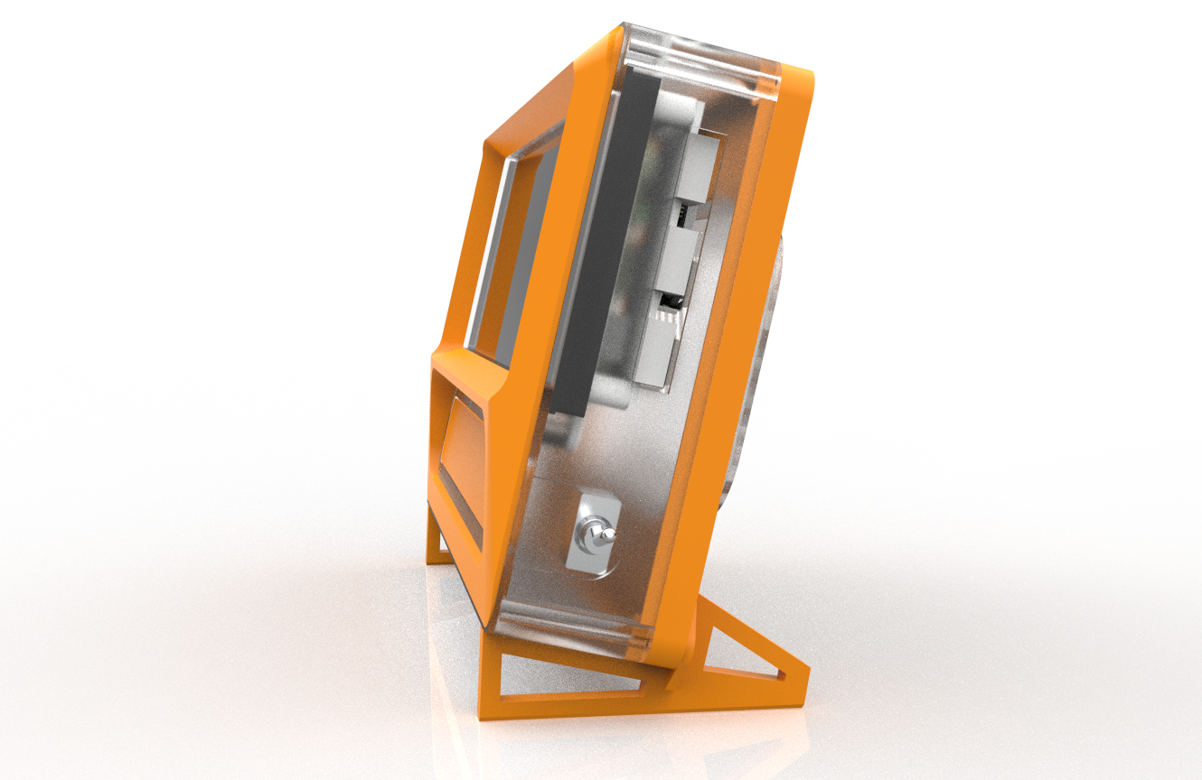
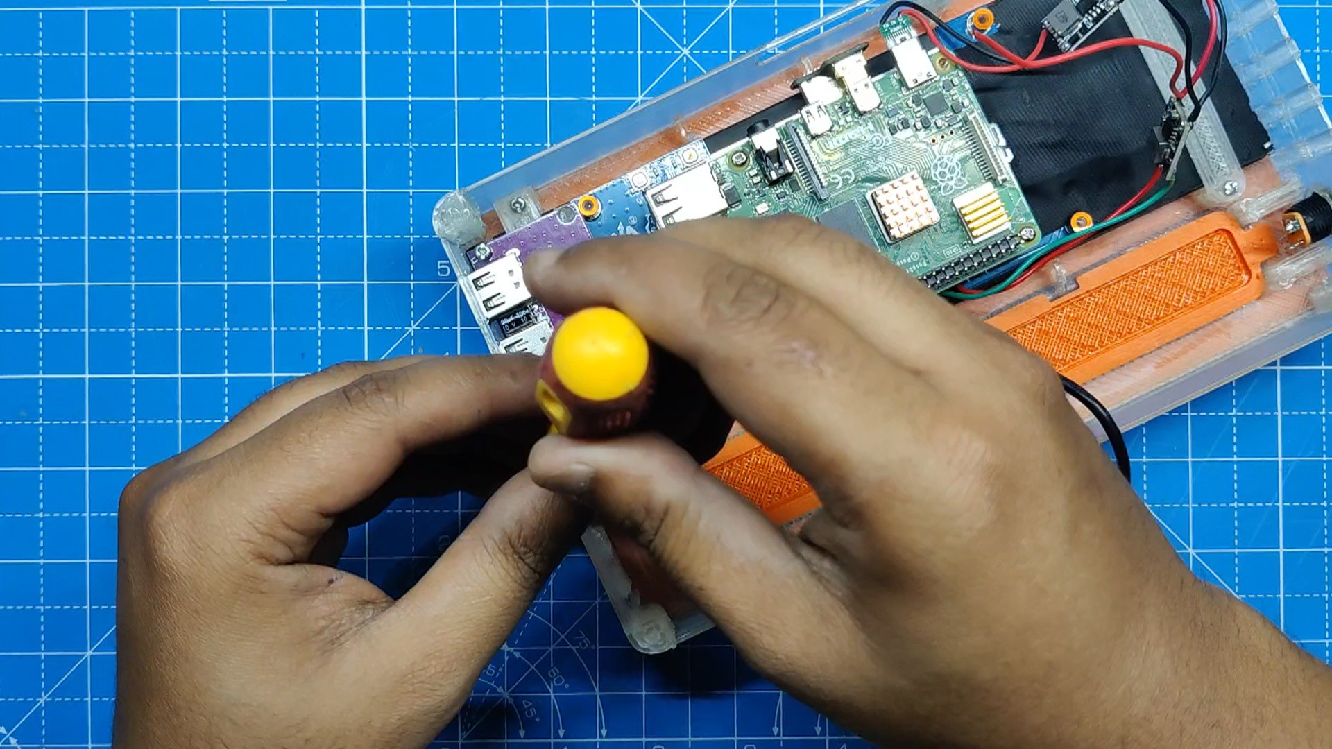
We also added a USB hub, which is installed on the left side of the model, since we could not access the USB ports on the Raspberry Pi because it was mounted in the middle.
On the right side, we have added a DC Barrel Jack connector for powering the Pi and the display.
There's also a switch added on the left side for turning power ON or OFF.
Once the model was finished, we took the entire design, rotated it by 13 degrees, and created a stand to support the entire model at a 13-degree tilt. We took this step since all of the old monitors had a slight tilt.
3D-printed parts
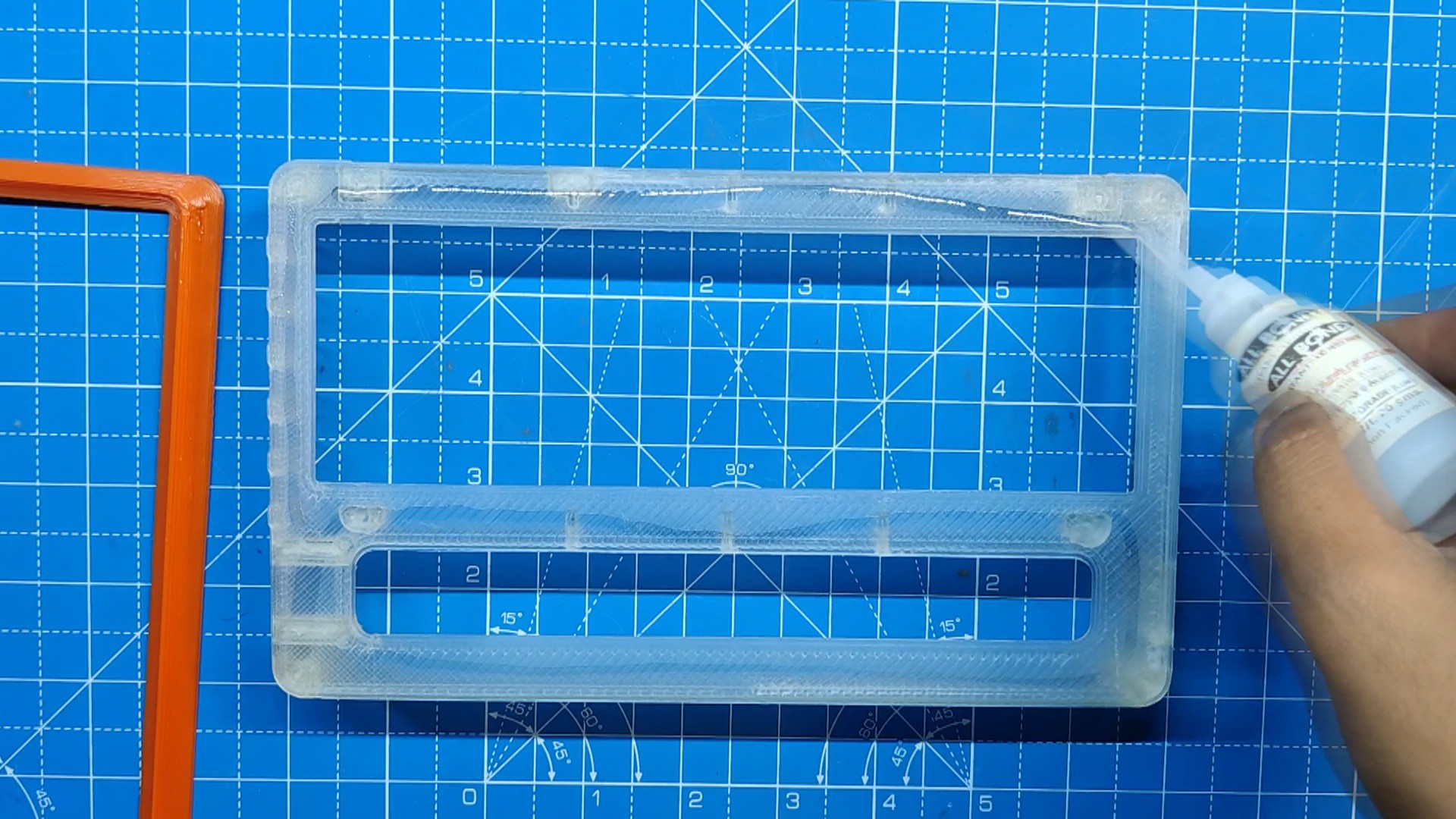
Following the design's completion, we exported each component into a mesh file and used two filaments—transparent PLA and orange PLA—to 3D print every part.
- Main Body: Transparent PLA with a 1mm nozzle and 0.3mm layer height
- Front Cover: Orange PLA with a 0.6mm nozzle and 0.2mm layer height
- Back Lid: Orange PLA with a 1mm nozzle and 0.3mm layer height
- Back Lid Grill: Transparent PLA with a 0.6mm nozzle and 0.2mm layer height
- Screen Holder 1: Transparent PLA with a 0.6mm nozzle and 0.2mm layer height
- Screen Holder 2: Transparent PLA with a 0.6mm nozzle and 0.2mm layer height
- IO Port Cover: Orange PLA with a 0.6mm nozzle and 0.2mm layer height
- Slot Part: Orange PLA with a 0.6mm Nozzle and 0.2m layer height
We use the above settings to print each part with our Ender 3 printer.
7.9-inch HDMI LCD DISPLAY
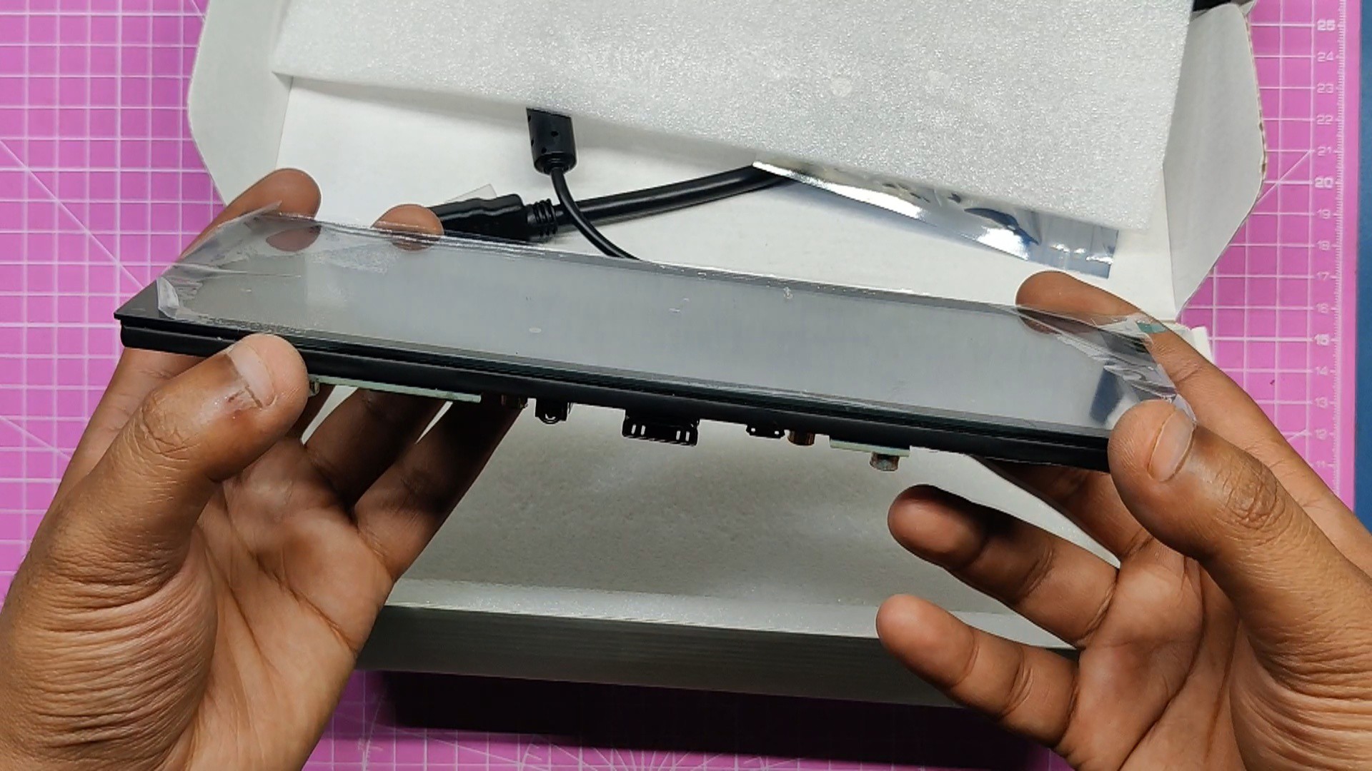
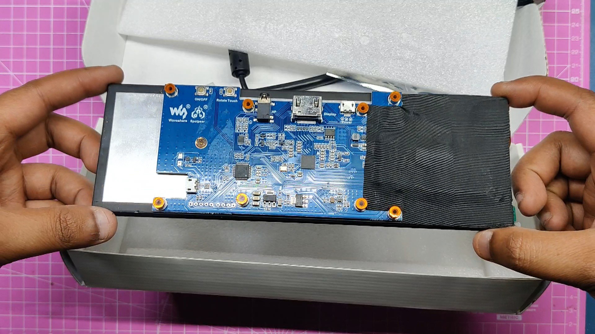
The Ultra Wide 7.9-inch HDMI Display, made by Waveshare, is the main component of this project.
This screen is fantastic; it has a 400x1280 pixel resolution and is incredibly bright. By holding down the ON/OFF button for an extended period of time, you can adjust the screen's brightness.
This is a 5-point capacitive torch screen that has a 6H hardness tempered glass panel.
This...
Read more »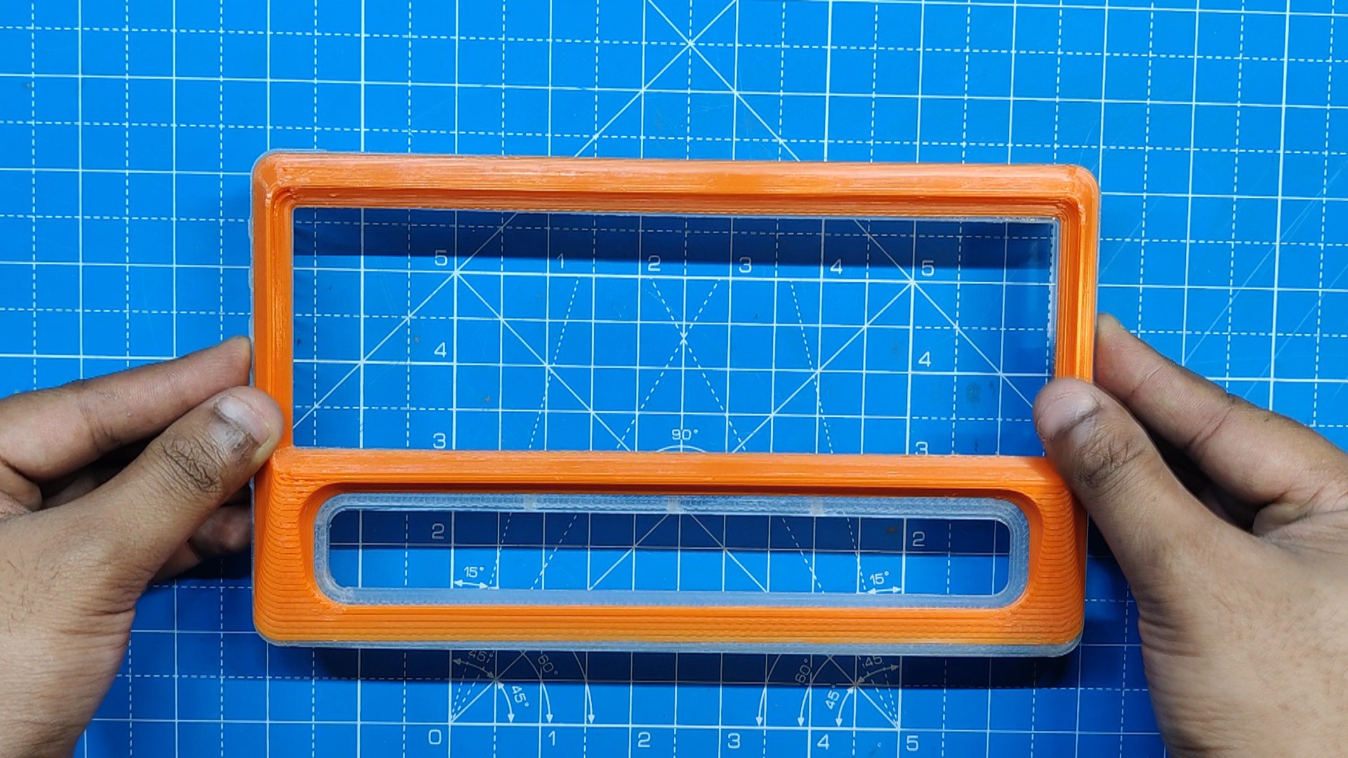
 shamylmansoor
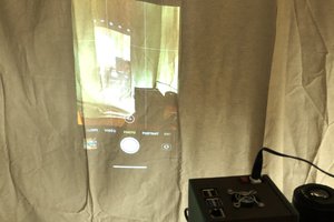
 hurðaskellir
 bobricius
 Tobias