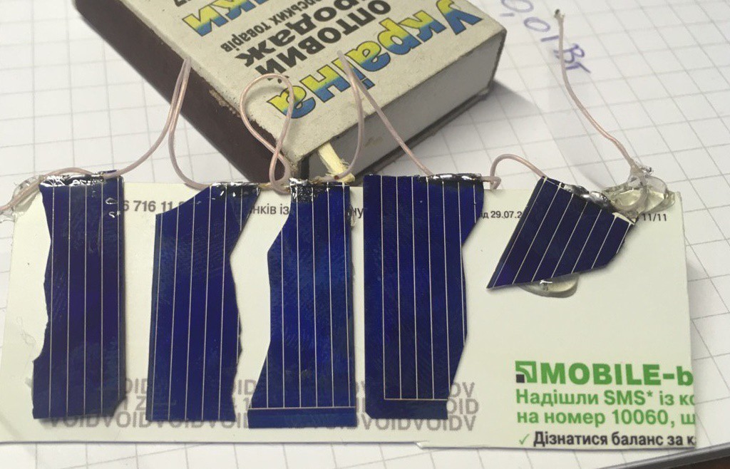
• Update 1: Schematic

    Yevhenii02/12/2017 at 23:40 0 comments

    Update 1:

    Now I have energy harvester schematic configured in boost mode. The main purpose - energy harvester testing. Stil I don't sure is SPV1050 right choise. So need to create test board and figure it out. Only problem - very fine pitch (0.4mm) so I need to use 0.15\0.15mm traces PBC (can't be done DIY). And shipping from china would take a lot of time.

    Fast shipping costs 3 times more than boards itself ;(

    In schematic there are possible to use one of four different inductors, four 10uF ceramic 0805 or one 47uF polarised cap, one of two different litium rechargable batteries or up to six 5.5V 0.22F supercaps. Some kind of flexibility.

    Next step: measure max power point to evaluate resistor values for harvester. Not complex but require time to measure VACs.

  • First time here ;)

    Yevhenii02/11/2017 at 21:38 0 comments

    Hi there.

    First small update is here. Github project created https://github.com/Riconec/Autonomous-solar-powered-wireless-sensor-node and have initial commit with altium libraries added for SPV1050 Harvester, STM32F070F6P6 (STM32F030F4P6 or another TSSOP20 STM32), STM32L011D3P6. Some pictures added.

    Next steps:
    1) Create schematic for SPV1050 in boost configuration.
    2) Measure VAC of different solar cells (currently I have two, but planned to have 2-3 more to find the best one). Software and hardware for measuring also can be created (or I can use keithley source meter and Labview program).
    3) Write a program to calculate passive components for SPV1050. Can be useful, I think.


    Pics:
    Solar panel made of two 0.5V 140mW solar cells ($2 10pcs).

    VAC of three solar cells (140mW 0.5V again) connected in series. Source of light - 60W light bulb.

    So stay tuned :)