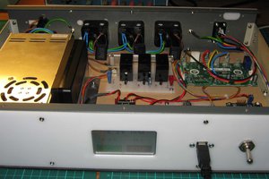
The Coolstat consists of 2 units. The control panel in the house and the power unit with relays that is outside in the cooler itself.
The two are connected by a 3 conductor cable. 2 conductors are power and ground (coming from the outside power unit). The third wire is labelled "Tx" and apparently sends commands to the power unit. A meter shows 3.3 volt levels on both power and the Tx line.
The Control Panel contains a very sparse PCB with an LCD, 6 buttons and a microcontroller. The controller is a Holtek HT46R64 chip. The 46 page PDF datasheet is available online. This is some kind of 8 bit RISC controller with 4K of program memory and 192 bytes (yes, bytes) of ram. It runs at either 4 or 8 Mhz. Most significantly it has OTP EPROM, so there is no hope of flashing new firmware. The reader should stop and ponder for just a moment how much of an upgrade replacing this with an ESP8266 would be.
I also have a project log on my website, but I will try to keep all the relevant details here as well.
Reverse Engineering
It was fairly quick work to connect this to a 3.3 volt supply (I already had one set up for another project) and put a scope on the Tx line. The control unit is "talking" at 4 Hz (every 250 ms) as you can see on the first of these scope captures. Presumably the slave unit ( the power controller ) will turn everything off if it does not get a message regularly (I should perform this experiment and find out how long it takes this "watchdog" logic to time out).


The message being sent is simple enough. It is a uniquely encoded serial byte sent at 1000 baud, i.e. each bit time is 1 ms as shown in this second scope capture:


We have a "start" sequence where the line is held high for two bit times (2 ms), followed by 8 data bits. Each of the data bits is 1 ms long, and like any good bit, comes in two flavors.
For each bit, the line is always first low, then high. In one state the line is low for 300 us, then high for 700. In the other state the line is low for 700 us, then high for 300. I call these states L and S respectively (for "long" and "short" refering to the high state time).
Messages look like SLSLxxxx, where "xxxx" are the bits of interest. The "SLSL" is a constant "prolog" that never changes. There is a 4 bit payload in each message. In the message shown above, the payload is "LLLL"
We can label the payload fgpx, and the 4 bits control:
f = blower high speed
g = blower low speed
p = water pump
x = purge pump
The "L" state indicates the feature is off, the "S" state indicates the feature is on. So the "LLLL" state shown above has everything off.
Note that we should never turn on both f and g (I don't know if the slave unit will guard against this or not, but I don't want to find out). Activating both relays to power both the fast and slow windings on the blower motor is almost certain to cause damage.
All the above was sorted out by using the buttons on the control module to put it in every possible state and making a chart of the different commands being sent.

 W. Jason Altice
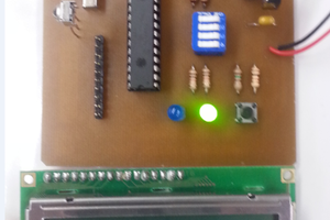
 Mark Atherton
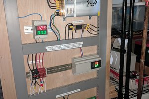
 Jason
Jason