 Gabor Futo
-
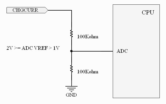
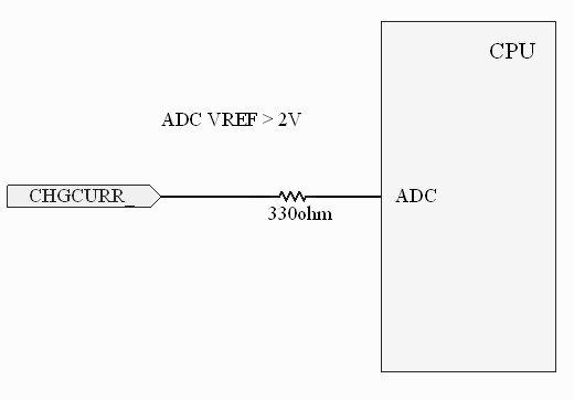
1Charge Current Measurement
You can measure charge current. Measuring in two ways: by ADC Vref range.
![]()
![]()
-
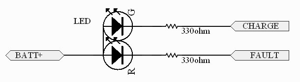
2State outputs
You can use two state outputs as follows:
- External LEDs:
![]()
- On CPU GPIO:
![]()
States on output:
![]()
- External LEDs:
-
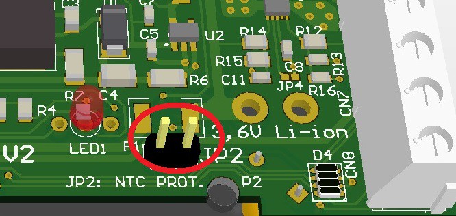
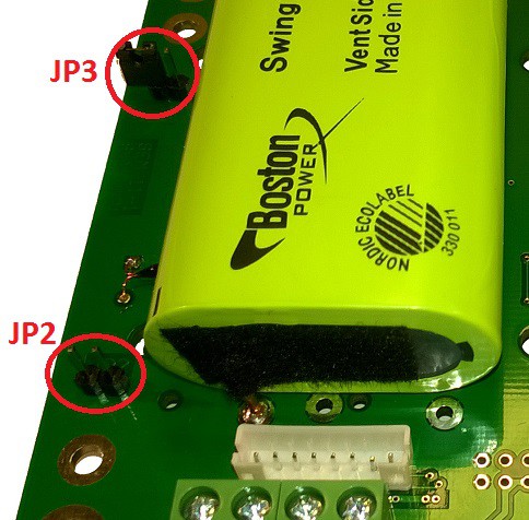
3Temperature protection
You can activate the temperature protection as follows: close JP2 jumper.
![]()
![]()
After that the charge will only work between 0 and 45 degrees (battery lifetime extension)
-
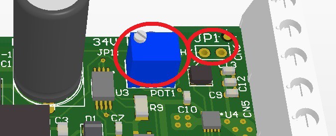
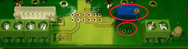
4Solar panel maximum power point setting
The MPPT charger settings as follows:
- Connecting laboratory power unit to DCIN
- Setting laboratory power unit to solar panel "voltage at max power"
- Measuring JP1 voltage
- Setting POT1 while JP1 voltage will be 2,75V
![]()
![]()
Default settings: 17.0-17.5V solar panel "voltage at max power"
-
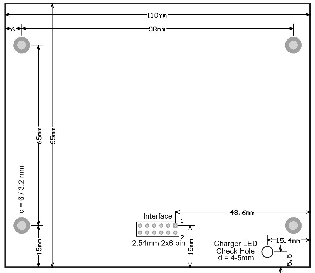
5Solar UPS V1 Mechanical Construction Guide
Application board dimensions and positions:
![]()
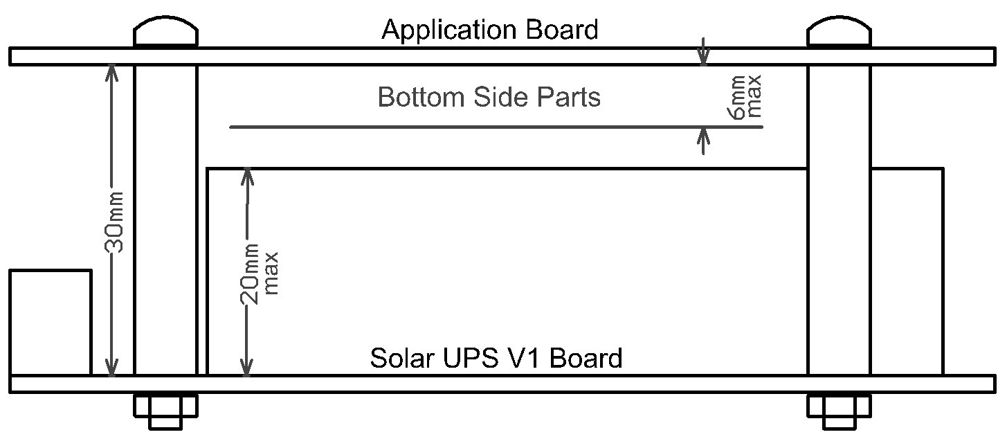
Sandwich structure dimensions:
![]()
Mechanical parts needed:
- M3 x 30mm steel spacer / 4 pcs
- M3 x 6mm steel screw / 4 pcs
- M3 x 2,4mm steel nut / 4 pcsSolar UPS board bottom side minimal distance 5mm.
Applicable IP67 protected Housing:
- Fibox Euronord ABS: AB121207 (65mm), AB121208 (75mm), AB121210 (95mm), AB121211 (105mm)
- Fibox Euronord PC (UV protected): PC(T)121207 (65mm), PC(T)121208 (75mm), PC(T)121211 (105mm) -
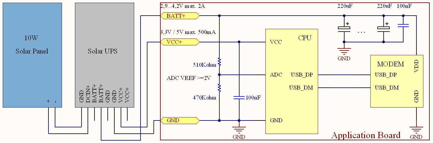
6Solar UPS module application schematic
Solar UPS module application schematic:
![]()


Discussions
Become a Hackaday.io Member
Create an account to leave a comment. Already have an account? Log In.