 Jorj Bauer
When I was a freshman at university studying electrical engineering, one of my professors laid this out pretty plainly for us: engineering tolerance is important. If you're designing a system that needs 1 amp of current, your power supply better support at least 2 amps. You want room for failure - particularly when you're first designing something and have no idea how all the pieces will interact.
That often means that, if you know what you're doing, you can push past the stated limits of systems as long as you're willing to accept some risks. In the last log entry, you saw me push a 20MHz SPI bus over 26 MHz before it broke. Will every copy of that display get 26 MHz? I don't know, but it's possible. Will something be damaged by pushing it that far? Possibly, but it's not likely (in this case).
In the quest to get beyond 7 frames per second, this is the realm I'm visiting. What kinds of limits can I bend or break, without causing any significant damage? is there a way to get an 800x480 SPI display over 12 frames per second? Or maybe as far as 30 frames per second?
The first step is to consult ye olde manuals. What are the variables here and how do they interplay?
We've got the SPI bus speed. On the Teensy side of things, I see reports of people getting that up to 80 MHz. I've certainly driven it up to 50 MHz. We're not near those potential maximums yet - and the current failure is on the RA8875 side anyway. So what are the limits there?
According to the RA8875 specification, page 62, the SPI clock is governed by the System Clock - where the SPI clock frequency maximum is the system clock divided by 3 (for writes) or divided by 6 (for reads). The system clock, in turn, is governed by the PLL configuration that's set via PLL control registers 1 and 2 (p. 39). The PLL's input frequency is the external crystal (on the Adafruit board that's 20MHz), and twiddling PLLDIVM, PLLDIVN, and PLLDIVK configures the multipliers and dividers for the PLL to generate its final frequency.
The system clock frequency is
SYS_CLK = FIN * ( PLLDIVN [4:0] +1 ) / (( PLLDIVM+1 ) * ( 2^PLLDIVK [2:0] ))
and looking at the DC Characteristic Table on page 174, we see that it's "typically" 20-30 MHz with a max of 60 MHz.
Now, the RA8875 driver (as distributed with the Teensy) sets all of this as PLLC1 = 0x0B and PLLC2 = 0x02, which means sys_clk is 60MHz. Right at the maximum limit specified in the datasheet.
Will it go faster? If we make it go faster, what else will be affected?
Looking for all of the references to the system clock, I see that the two PWMs use it. PWM1 is being used to drive the backlight, so that might be important at some point, but probably isn't critical. More importantly: the pixel clock is derived from the system clock.
The pixel clock is how the data is being driven out to the display. While I see various generalities about the pixel clock required for different sized displays that suggests 30-33MHz for a 800x480 display, I don't have the numbers for the actual display I'm using. And looking at the RA8875 manual and doing the math, it looks like the pixel clock is actually 15MHz here, so those "normal" values are either unimportant or wrong. Either way there's not much to do be done about it until we understand more of what's going on.
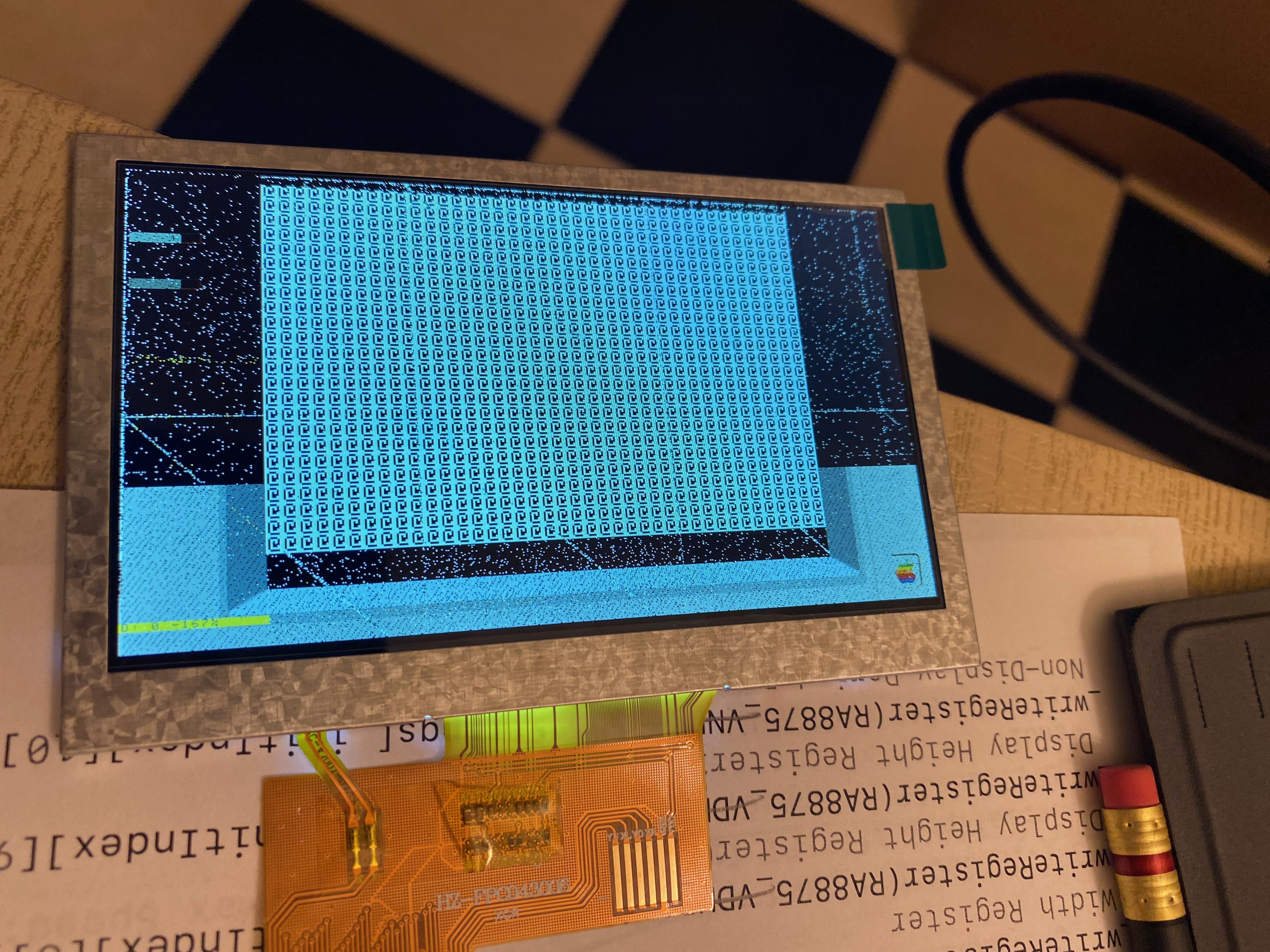
So, let's jump in the deep end! What happens if we maximize PLLDIVN (set it to 31), minimize PLLDIVM (set it to 0) and minimize PLLDIVK (set it to 0 also)? Short answer: nothing. A black screen. So we can't just set it all the way to the maximum. But a little bit of binary searching shows that we can actually set it to other values in the middle and it works with our 26MHz SPI bus just fine, and a sys_clk that's over 60MHz. How far? As far as 150MHz. Along the way I found that the display would break down in very interesting ways... like this, when pushing the SPI bus faster than the clock wanted:
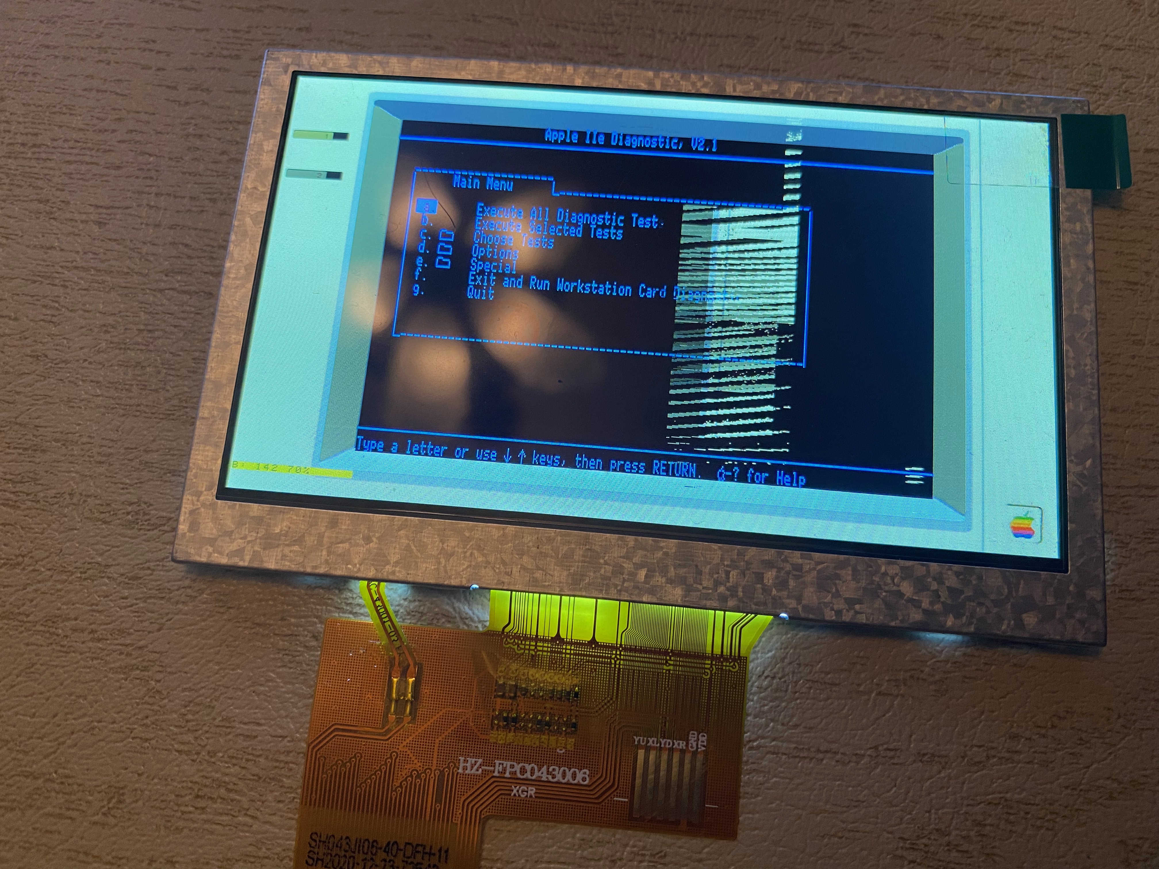
Or this, when the pixel clock started drifting too far out from what the panel wanted:
but with a lot of experimentation, it looks like I can get a good solid display with the PLL frequency at 300MHz; the system clock at 150 MHz; and the pixel clock at 18.75 MHz. That lets me push the SPI bus up quite a lot - at 57.5 MHz I'm getting 14-15 frames per second with a good solid display. At 60MHz there are occasional color shifts like the psychedelic display above, though not as severe; and the display goes dark at 80MHz (although it works at 79.999999 MHz, so I suspect there's some magic constant in the Teensy software or the Teensy 4.1 hardware someplace that's cutting it off at 80 MHz).
What are the tradeoffs, then?
- I have no idea if this will work on other panels, or if it's just the one I've got.
- There are two integrated CPUs on the RA8875, and it's possible that neither of them will run reliably.
- There are character ROMs that might not work properly.
- The RA8875 has its own DMA access to an SD card that probably won't work.
- The PWM rates are definitely affected and could be an issue depending on how the backlight is being fed.
- The increased SPI bus rate on the Teensy means it's using more processing power "invisibly" transferring all that data. The audio channel also does the same, so there's potential conflict there.
Most of those are ignorable for now - I don't care about the features related to 2, 3, and 4. 5 seems to be fine empirically. We'll find out about 1 as more people test with this hardware and configuration. Which leaves 6.
There's definitely a problem with the increased SPI bus rate. As I pumped it up I started getting warnings about the audio buffer overflowing -- so as compensation, I've bumped up the audio buffer size tenfold (from 4k to 40k).
All this goes to show a few things.
The Adafruit support forum was wrong about the maximum SPI clock frequency, at least in the general case (or maybe I totally misunderstood what they were trying to say). It is not related to or capped at the 20MHz oscillator. Maybe what they said was true for their own driver under some other circumstances, but it's not a globally correct statement.
The stated maximums in the RA8875 manual for the CPU are not true for my use case. Again, it makes sense for the general-purpose driver to "set it and forget it" at the documented maximum, but for my purposes I can do more.
Understanding the manual is really helpful. Without knowing the way that these registers worked or were related to each other, I wouldn't have been able to easily identify which four values were related - how they are related, what their minimum and maximum settings are, and more importantly when I started seeing problems I wouldn't have had any idea which setting was likely the culprit in that circumstance.
Work it harder, make it better
Do it faster, makes us stronger
More than ever, hour after hour
Work is never over
Discussions
Become a Hackaday.io Member
Create an account to leave a comment. Already have an account? Log In.