 Boian Mitov
-
1Step 1
Unboxing the robot
-
2Step 2
Assemble the camera mount
- Take the Cross shaped Seat and place it on the Plastic Base
- Use 4 small screws to secure the seat to the Plastic Base
- Insert the servo into one side of the Pan Bracket
- Make sure that the servo shaft is at the opposite side from the pivot point for the tilt bracket
- Place the second pan bracket over the servo until it reaches the first bracket, and the 2 completely wrap the servo
- Tighten the 2 brackets together with screws
- Take the short single sided seat and place it in the bracket that has fitting for it with the connection for the servo pointing inwards
- Tighten the bracket with 2 screws
- Insert the shaft of the second servo into the main hole of the seat attached to the Pan Bracket
- Place the tilt bracket on top of the second servo so that the shaft aligns with the pivot hole
- Tighten the servo with 2 screws
- Attach the Seat to the Servo with small screw
- Insert the shaft of the servo of the Pan Bracket to the main hole of the Seat on the Base
- Attach the Seat to the Servo with small screw
- Take the camera base, and snap it to the Tilt Bracket
- Take the camera, and snap it to the Camera Base
-
3Step 3
Installing the Arduino, Motor control, Servo control, and Wi-Fi Boards
- Take the WiFi board, and place it on top of the big flat area in the back of the chassis
- Move the board around until you find a good set of holes where you can use bolts to mount the board to the chassis
- Take the Arduino board, and place it on top of the big flat area in the back of the chassis
- Move the board around until you find a good set of holes where you can use bolts to mount the board to the chassis
- Attach 3 standoffs with bolts to the chassis at the holes selected for the Arduino board
- Mount 4 standoffs with bolts to the Wi-Fi Board
- Place the Wi-Fi board underneath the chassis and attach the standoffs to the chassis with bolts at the selected hole locations
- Mount the Arduino board on top of the 3 standoffs that were prepared for it with bolts
- Plug the Motor Driver Shield on top of the Arduino Uno
- Plug the Servo Control Board on top of the Motor Driver Shield
-
4Step 4
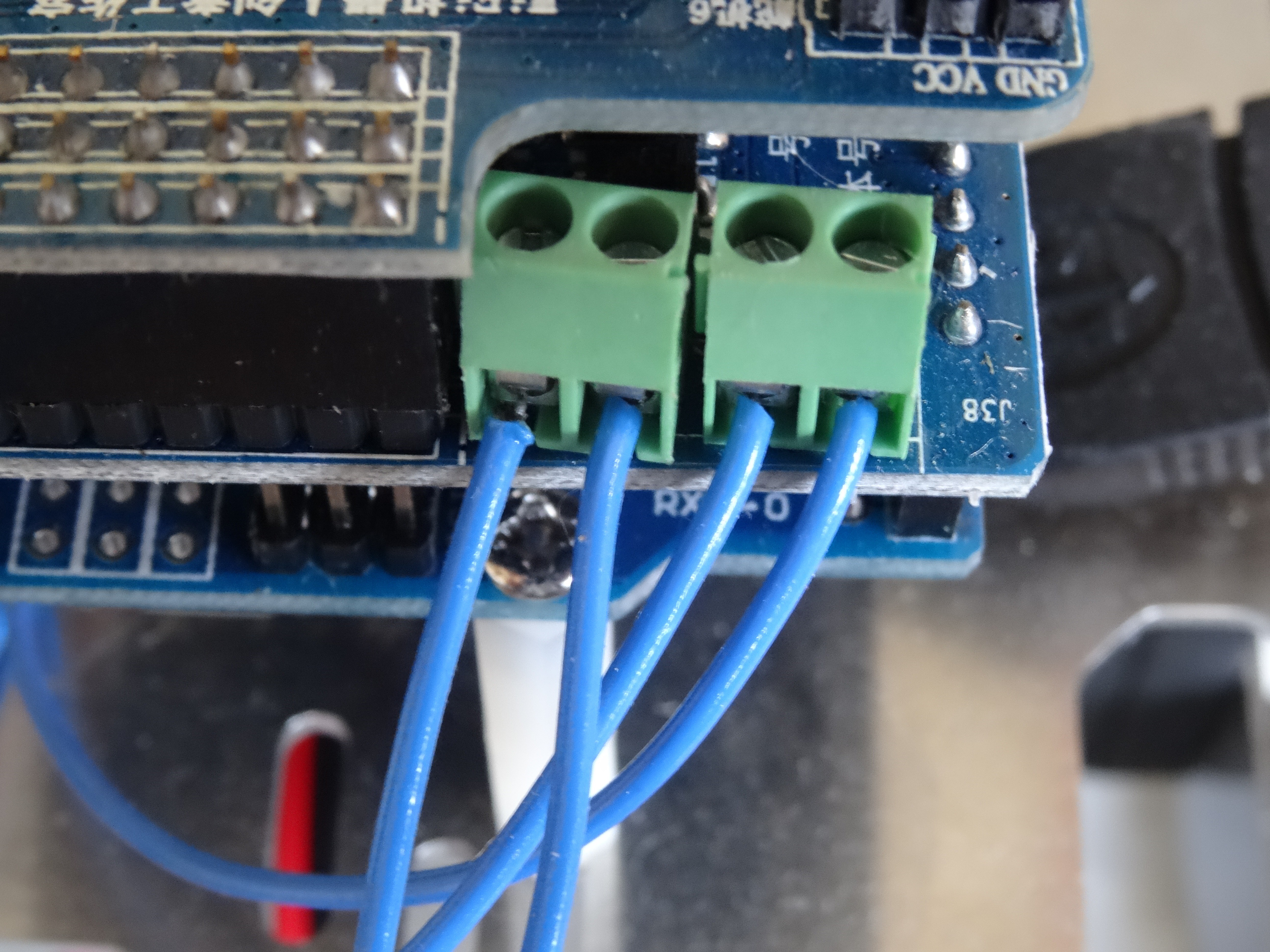
Connecting the Driving Motors to the Motor control Shield
![]()
- Strip the insulation from about 8mm from the end of the 4 wires coming from the motors
- Twist the stripped ends of the wires
- Optionally use soldering iron to tin the stripped ends
- Use a small screwdriver to unscrew the 4 bolts on the motor control connectors on the motor driver board
- Protrude the wires through the opening in the chasses underneath the Arduino board
- Insert the 2 wires from the left motor into 2 connection points of the left motor control connector
- Tighten the wires into the connector ny tightening the bolts of the connector with the screwdriver
- Insert the 2 wires from the right motor into 2 connection points of the right motor control connector
- Tighten the wires into the connector by tightening the bolts of the connector with the screwdriver
-
5Step 5
Installing the Wi-Fi Camera
![]()
- Place the camera base on top of the front of the chassis
- Use 4 bolts and nuts to tighten the camera base to the chassis
- Leave the 4 bolts not completely tighten so you can adjust the camera position later if needed
-
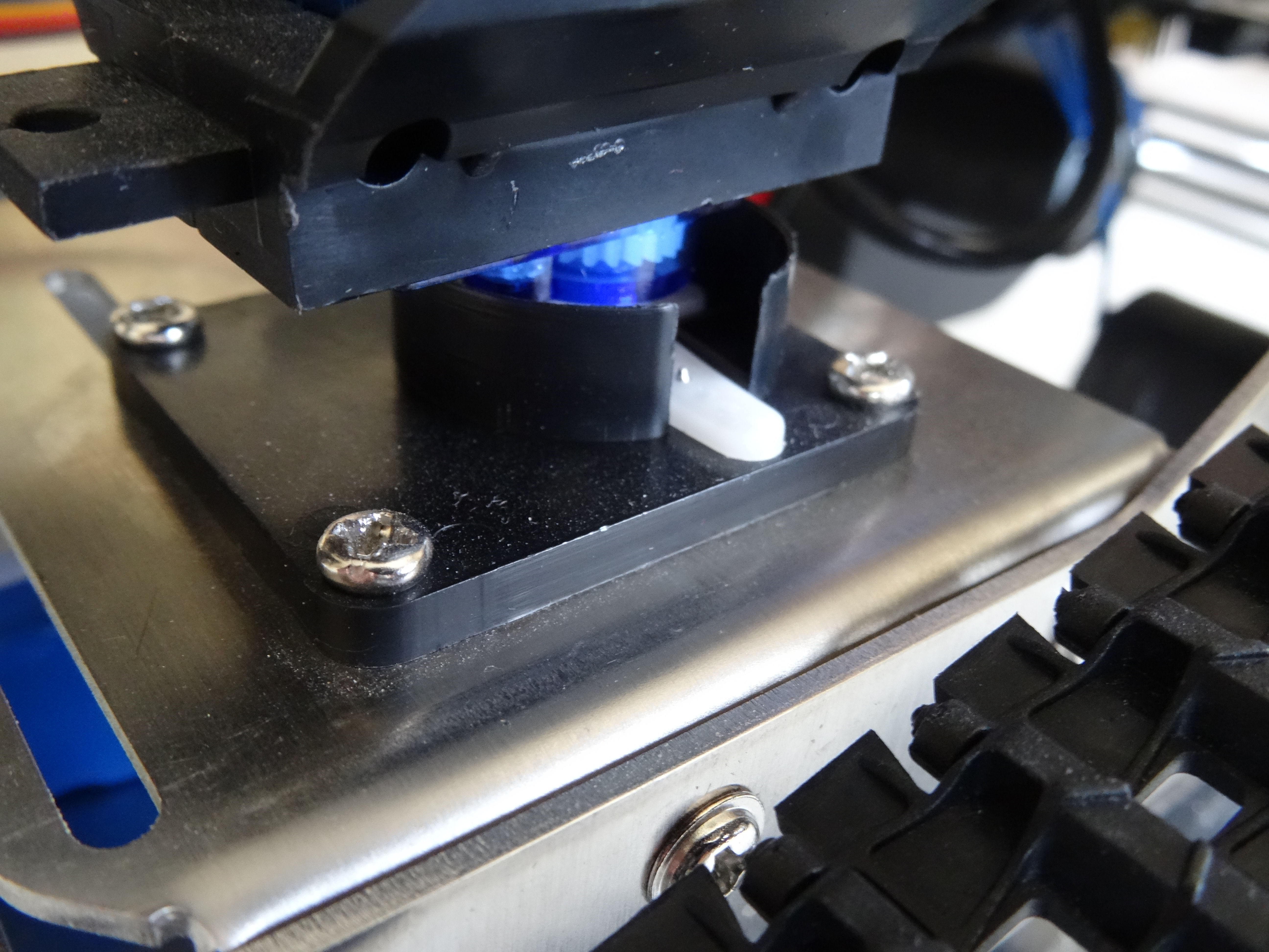
6Step 6
Installing the Manipulator
![]()
- Place the Manipulator base on the sloped front of the chassis
- Use 6 bolts and nuts to tighten the manipulator base to the chassis
- Leave the 6 bolts not completely tighten so you can adjust the manipulator position later if needed
-
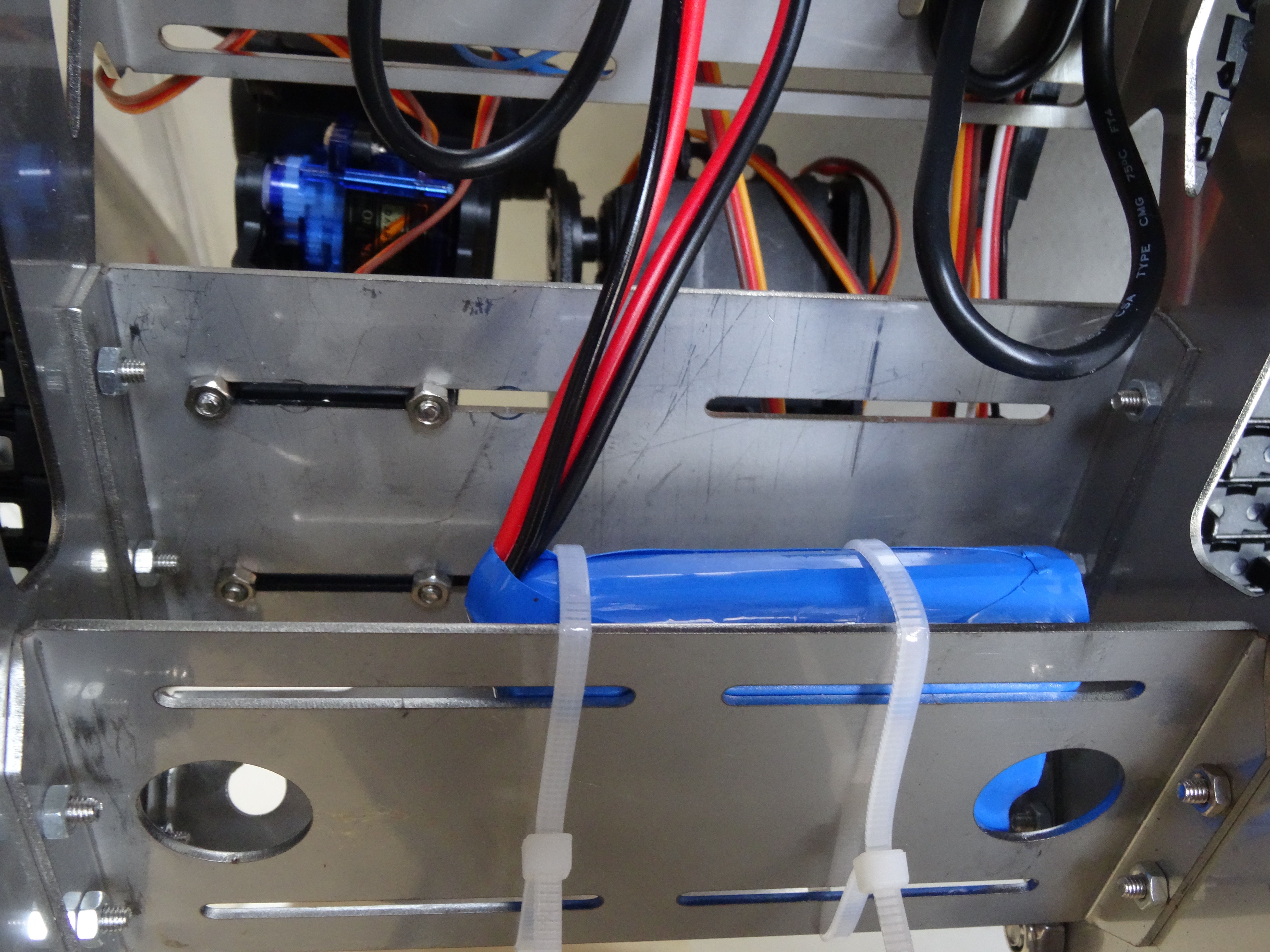
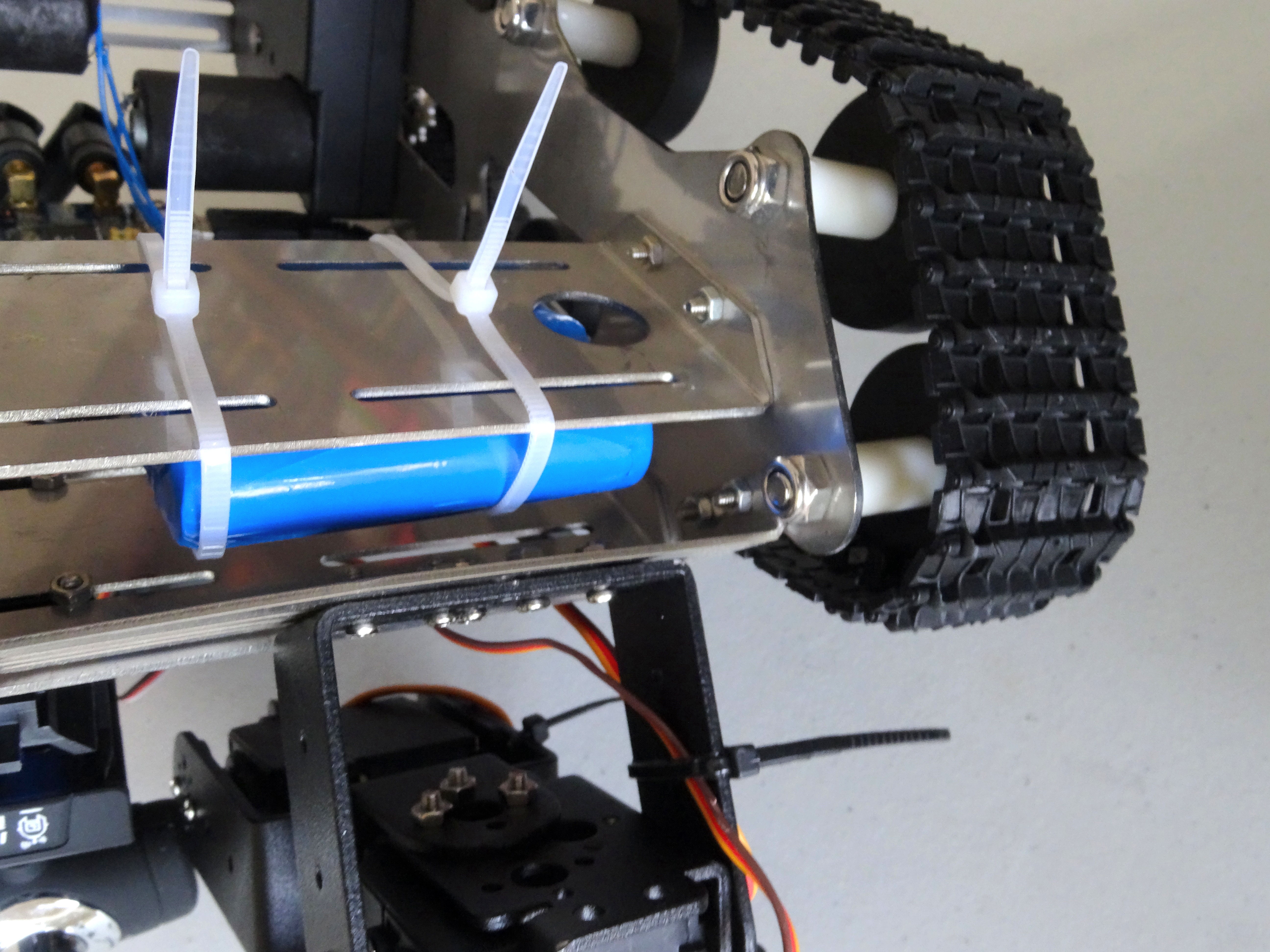
7Step 7
Installing the Rechargeable Battery
![]()
![]()
![]()
-
8Step 8
Connecting the USB cables
-
9Step 9
Connecting the Camera Mount and the Manipulator Servos
-
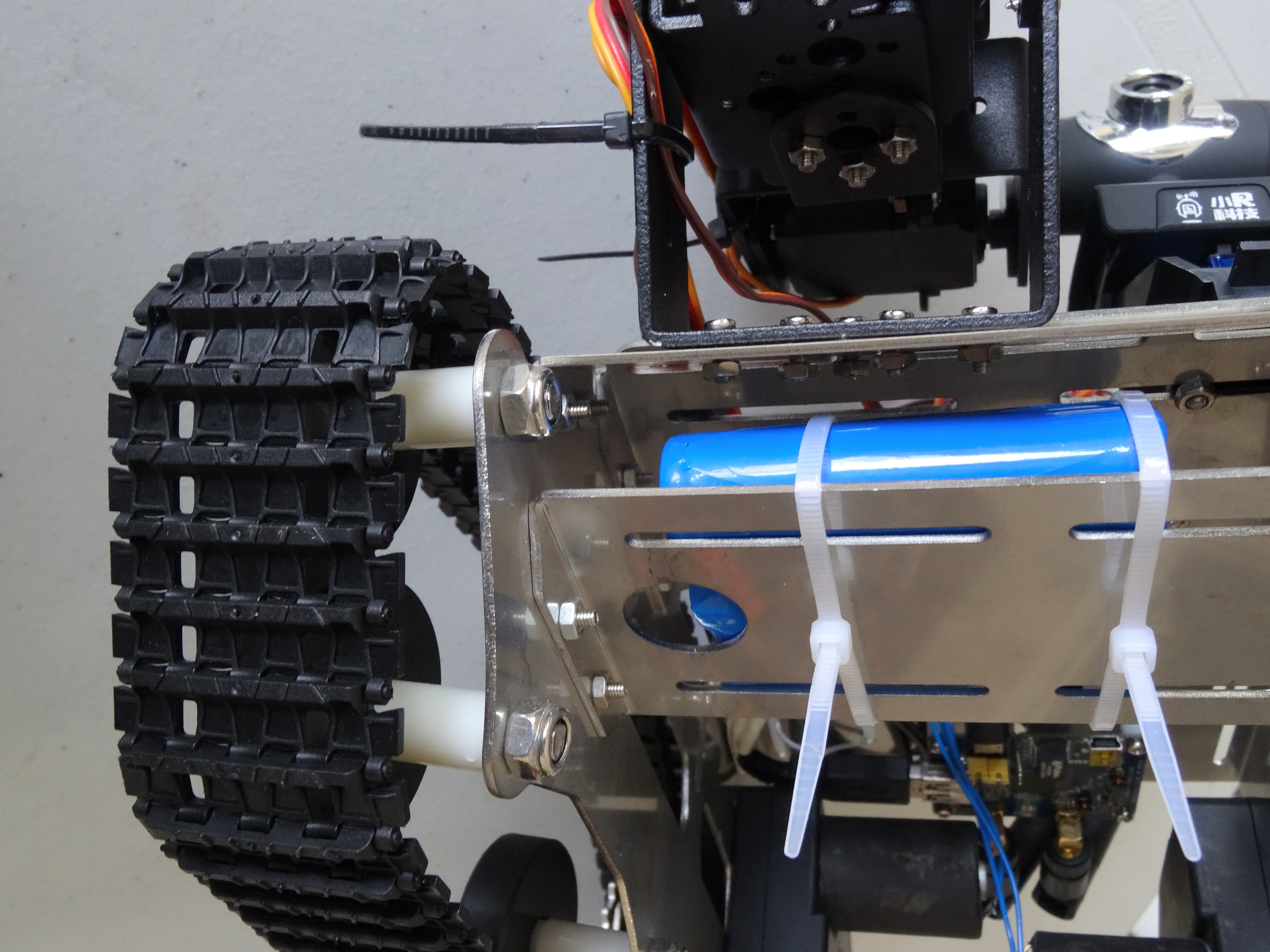
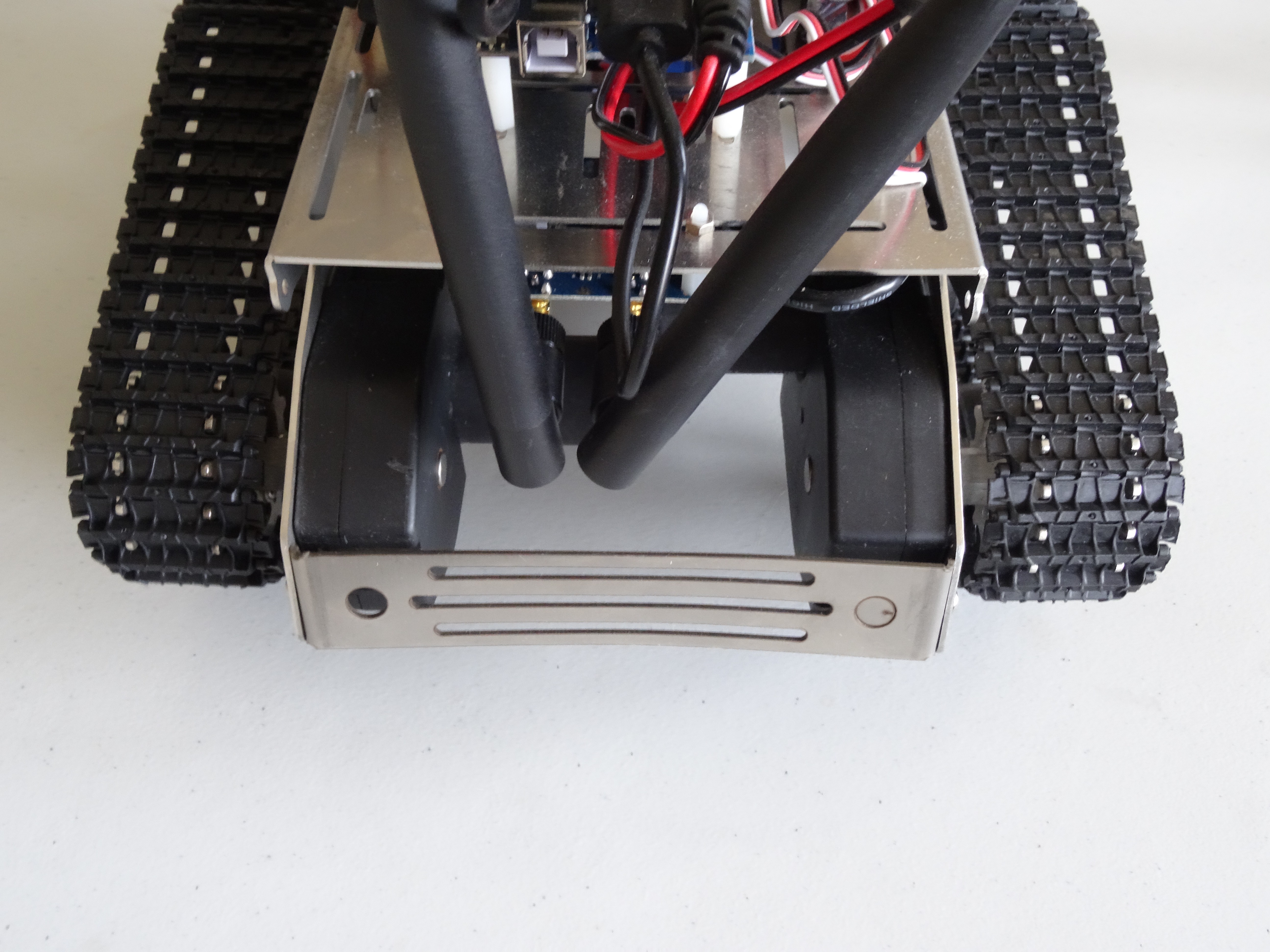
10Step 10
Connecting the Battery and Installing the Antennas
![]()
Kuman Wi-Fi Robot with Camera and Manipulator
Assemble and Program Kuman Wi-Fi Robot with Camera and Manipulator

Discussions
Become a Hackaday.io Member
Create an account to leave a comment. Already have an account? Log In.