 borazslo
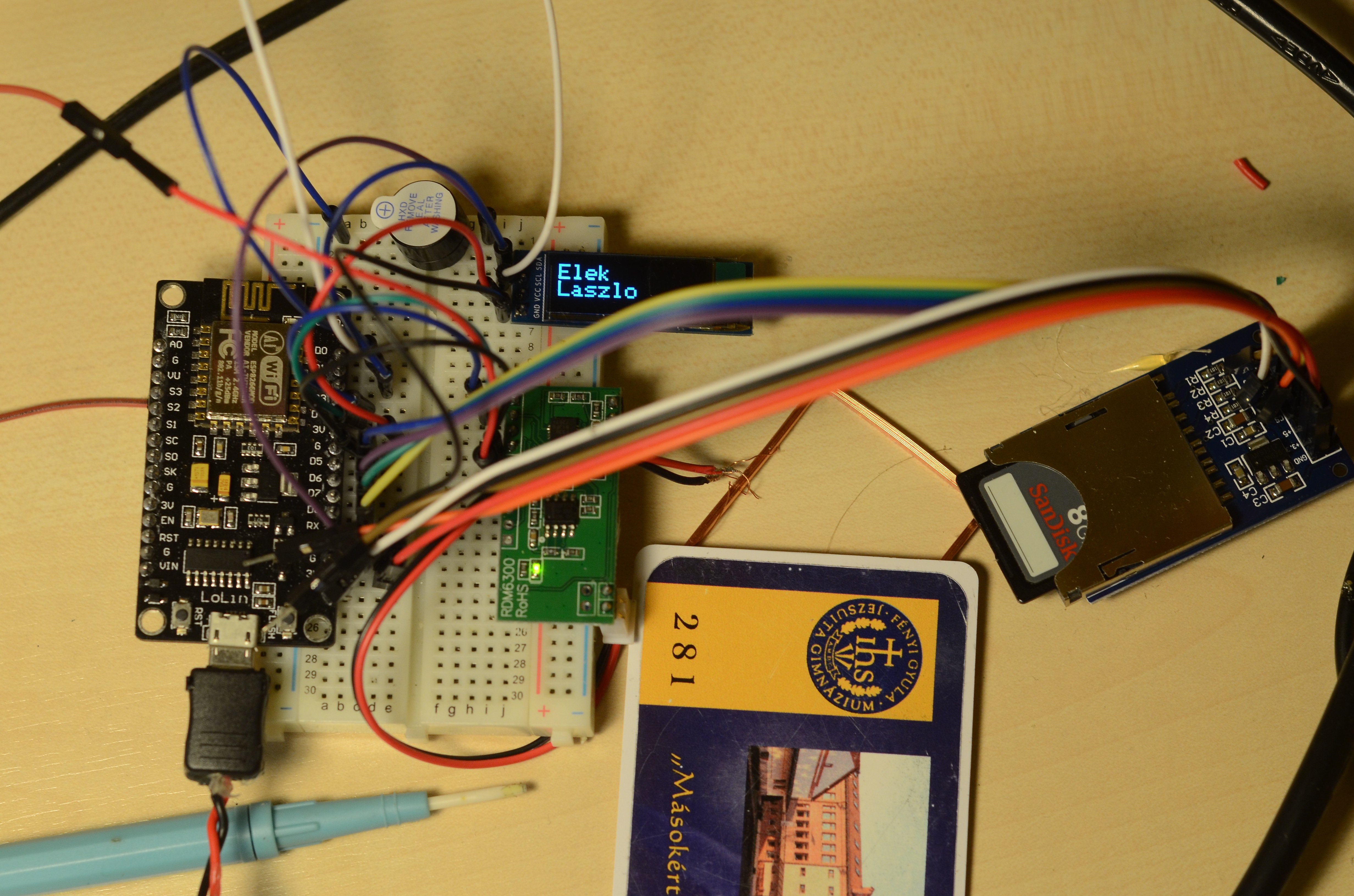
125Khz RFID module - NodeMCU: softwareSerial communication
- RFID P1 PIN1 TX - NodeMCU D3 (It can be changed in the code.)
- RFID P1 PIN2 RX - NodeMCU D4 (It can be changed in the code.)
- RFID P1 PIN3 - - -
- RFID P1 PIN4 GND - NodeMCU GND
- RFID P1 PIN5 +5V(DC) - NodeMCU VV
+5V DC should be detached during firmware upload, because NodeMCU D3 is used also for FLASH.
SD Card SLOT - NodeMCU: SPI communication
- SD Card Slot GND - NodeMCU GND
- SD Card Slot +3.3V - NodeMCU 3V
- SD Card Slot +5V - -
- SD Card Slot CS - NodeMCU D8 (It can be changed in the code.)
- SD Card Slot MOSI - NodeMCU D7
- SD Card Slot SCK - NodeMCU D6
- SD Card Slot MISO - NodeMCU D5
- SD Card Slot GND - -
128x32 OLED Display - NodeMCU: I2C communication
- OLED GND - NodeMCU GND
- OLED VCC - NodeMCU 3V (!)
- OLED SCL - NodeMCU D1
- OLED SDA - NodeMCU D2
- There is no OLED Reset pin on my OLED display. In the code we need to attache a pin number to OLED Reset. I choose D9. So I have no Serial Monitor, but I have everything else. It can be D0 as well, if there is no buzzer attached to D0.
Buzzer - NodeMCU
- Connected as usual. Now between NodeMCU D2 - NodeMCU GND
NodeMCU D0 is used during flash of new firmware, so the buzzer needs to be disconnected during firmware update.
Please give me suggestions how to optimize these connections. How can I use for example A0, S3, S2, S1, SC, S0, SK, EN pins of NodeMCU?
Discussions
Become a Hackaday.io Member
Create an account to leave a comment. Already have an account? Log In.