 alexw
alexw-
Printing and assembly
04/18/2017 at 15:39 • 3 comments![]()
Having produced a complete CAD model of the glider, I started printing the parts for the glider. I own a Mini Kossel printer, which is a delta style printer (as opposed to the standard cartesian printer) The components were printed at a layer height of 0.4mm, for greater structural strength and faster prints. Printing all the pieces took approximately 80 hours. I had to print some pieces multiple times to get the dimensions of some features correct (bolt and tubing holes, etc).
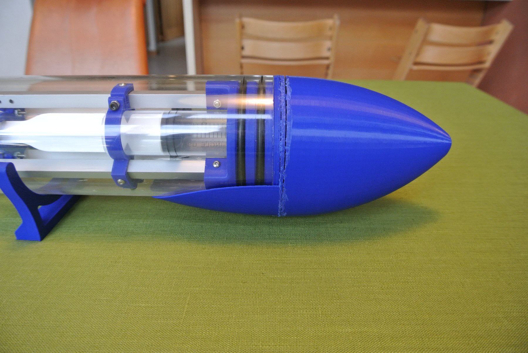
The hydrofoils attach quite firmly to the glider body and are unlikely to slide off during operation.For the majority of the parts, no post processing was required, but for a few parts the printer had a printing error which caused the layers to become stepped (I have since fixed this error). As the printing error would not affect functionality, I decided to not redo the prints and would clean the affected pieces using a dremel.![]()
The nosecone pieces after post processing, you can see the stepping error at the join![]()
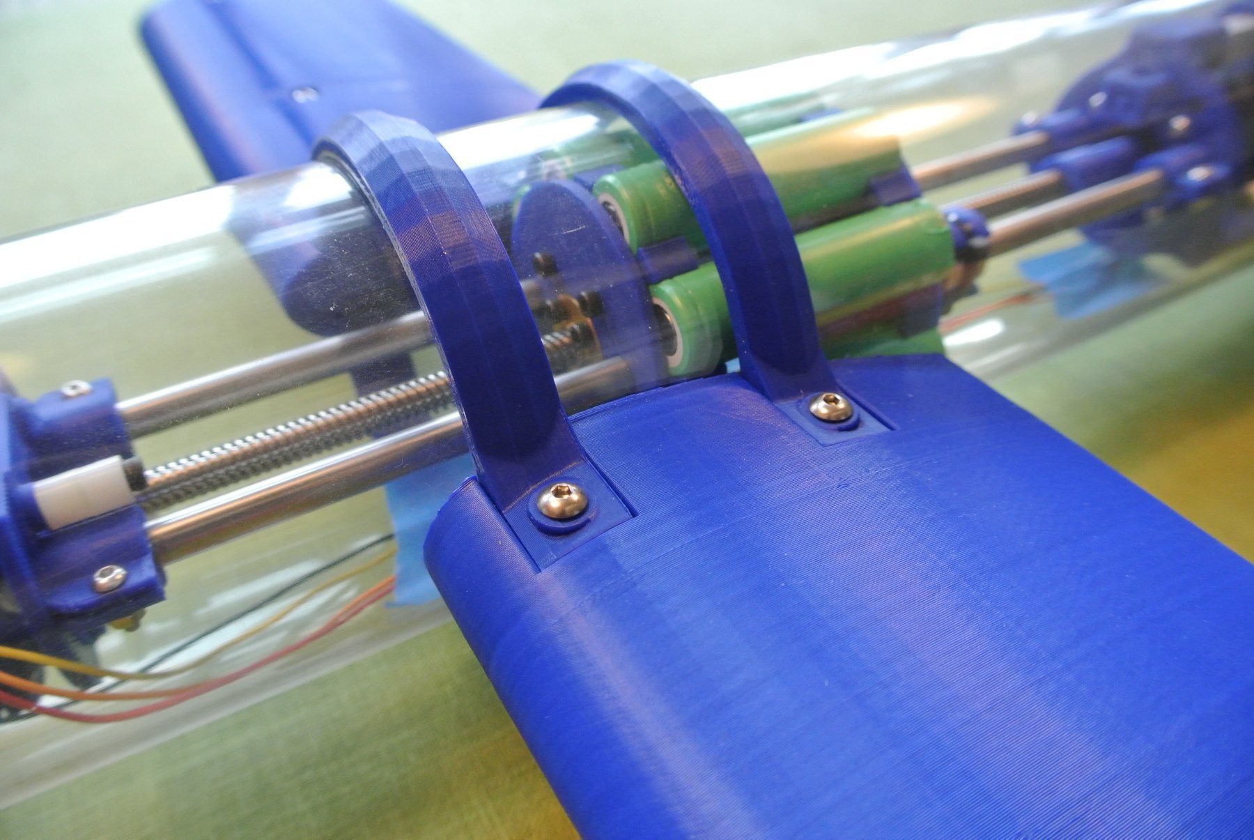
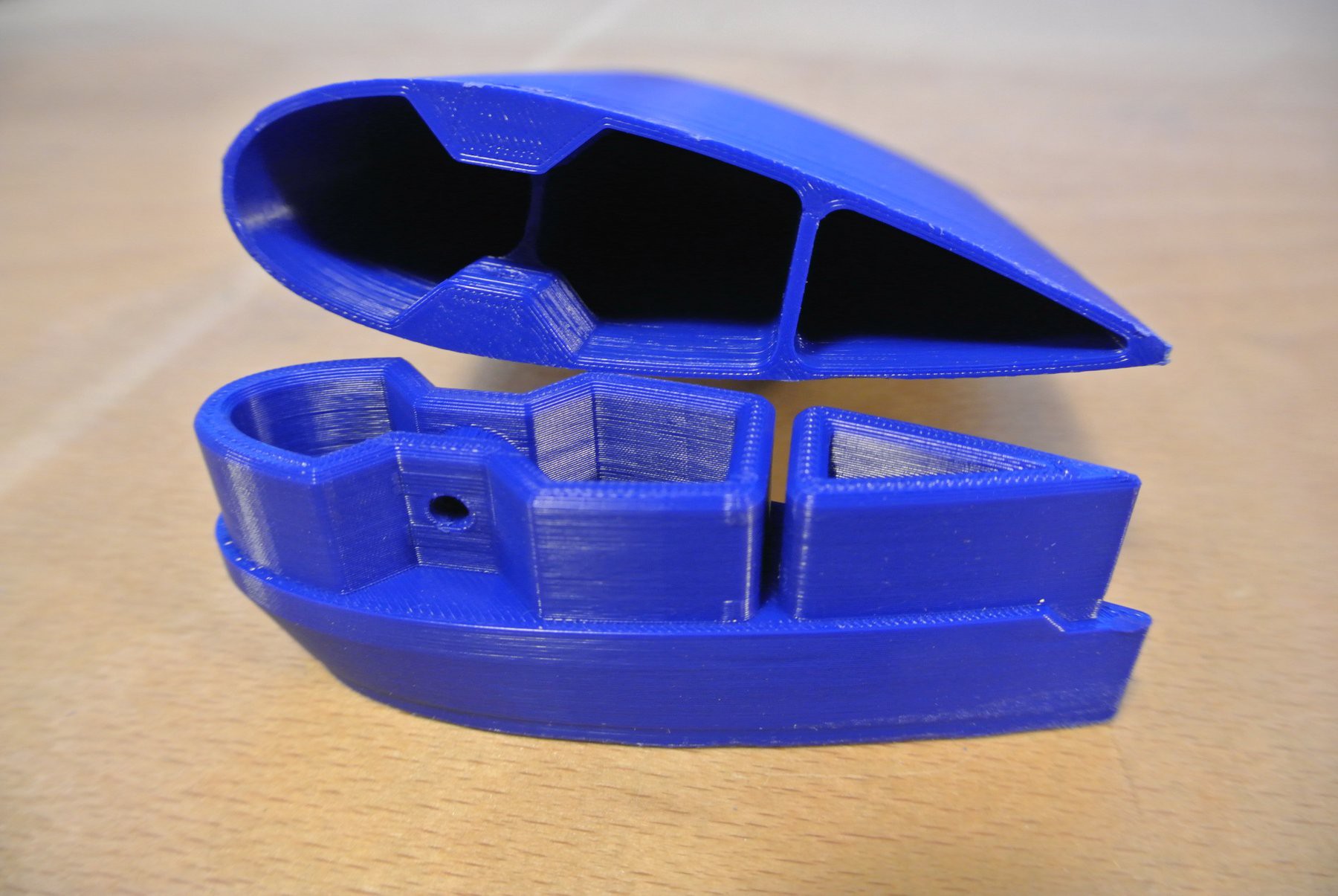
Printed material is less dense than water, so I made the models hollow in some areas, so that they could be filled with ballast. I am going to use a PVA/sand mixture as the ballast, as this is denser than water (~1.7g/cc depending upon the ratio of PVA to sand) and can be formed quite easily.
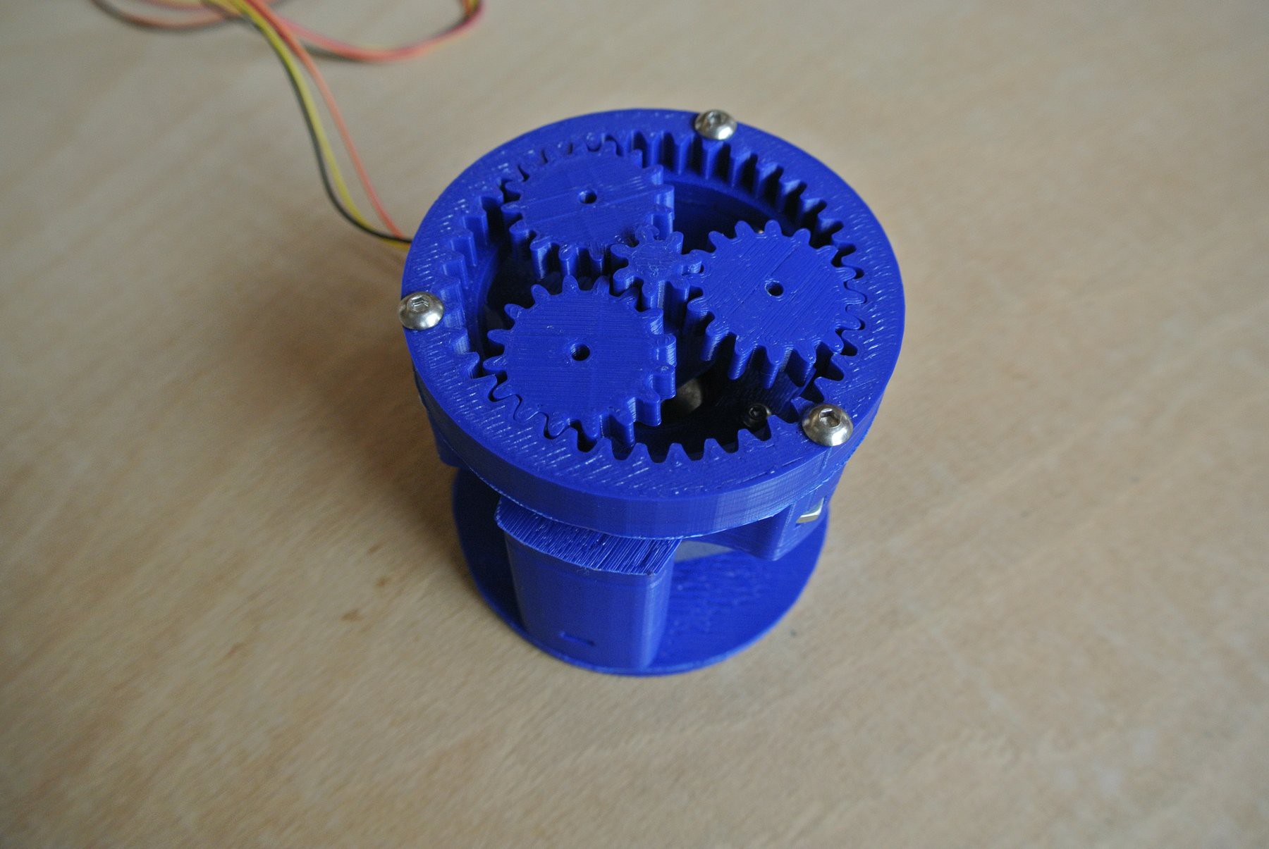
The hollowed internals of the hydrofoils, ready for ballastThe planetary gearbox also required a lot of work regarding the tolerances of the gears. Although it is not perfect and there is still a slight amount of slip, I am happy with it to a sufficient degree for a proof-of-concept.![]()
![]()
I have hooked the stepper motors up to an Arduino and over the next week or so, I will test the movement sub-systems and post a build update showing basic functionality.
-
Designing the underwater glider
04/02/2017 at 15:30 • 0 comments**The model is viewable on the Onshape online platform here (requires webGL)**
![]()
As I had a rough idea of how the internals of the glider would be placed, I produced a few sketches to see how practical the layout would be. From these initial sketches, I used Solidworks to turn these sketches into CAD models, ready for printing. To ensure that all of the printed components would fit together, without the need for post processing, I produced a virtual assembly of the glider within Solidworks.
![]() One of the early sketches of the glider
One of the early sketches of the glider![]()
A few different views of the buoyancy engine
![]() A top view of the glider
A top view of the glider
I knew whilst designing the CAD models that I would be 3D printing the glider, therefore I was able to optimise the design of the components for printing (limited overhangs, larger design features, hollowing out, etc). I will now start printing the components on a 3D printer (a mini Kossel) and update the builds logs once printing has finished. I will also upload all the STL files over the next few days so that others can print the underwater glider.
OSUG: Open-Source Underwater Glider
A versatile autonomous environmental drone using a buoyancy engine


 One of the early sketches of the glider
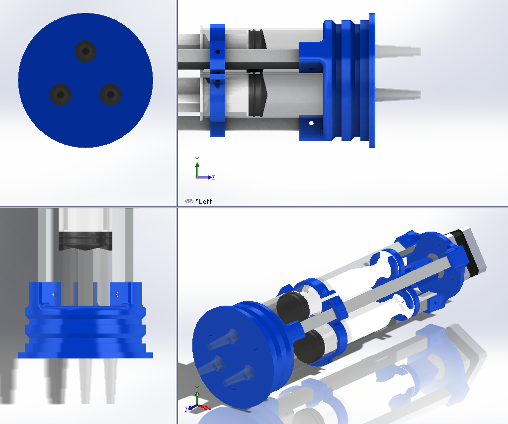
 A top view of the glider