-
Ethernet Success
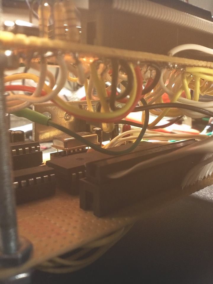
05/09/2015 at 16:59 • 0 commentsI was considering using an ethernet to serial converter, and using an AT command protocol to connect to the ethernet. Realizing this would tie up the only serial port, I didn't want to do that: Bridging ethernet and serial may be one area where such a limited computer could still be useful. I found online another one of the same ethernet sheilds I previously destroyed, this time on clearance for $5. I decided to try again.
The issue I had previously was a bus collision. The Wiznet 5100 chip does not release the MISO line, instead it drives it low continuously when idle. This happened while PORTB was either talking to the sdcard, or while the AVR was driving video, in either case, it was bad news for the W5100.
The W5100 does have a 'spi enable' line, which can be driven in inverse to SS, to force it to release the bus. This workaround is covered in a Wiznet application note, and this feature is largely regarded by the internet community as a bug. This line is made available on this ethernet shield as a tiny pad I suppose I could solder a small wire to.
Instead, I decided to try adding a tri-state buffer. I had previously used a 74HCT244 to buffer and level shift the SDCARD, which was also a 3.3v SPI interface. I tried it, but this time I had problems, unless I used a very slow SPI clock rate. When I bench test the buffer on a breadboard, it switches fine: 3v is plenty for a TTL high. After all, I can talk to the sdcard 5Mhz SPI rate with no problem. Then I decided to double-check the data sheet. The W5100 only guarantees 2.0V logic highs. When I checked the sdcard specs, it guaranteed .75 * supply, so 2.47 volts.
At this point, I knew the wiznet was being written to correcly by the SPI bus, because I could set its IP address, and it would respond to pings from my desktop computer. But reading registers from the Wiznet produced garbled data. After checking very carefully that the sdcard was disabled, and its buffer's CS line was held high, I directly connected the MISO pin from the Wiznet to the AVR. The data read back correctly. The AVR guarantees anything 2.5v (supply/2) is a high. Due to the number of direct-connected Arduino shields produced, I suspect the real numbers on AVR are a little lower (can read a little below 2.5 as a high), and most Wiznet's produce a little more then 2v as a high. The range of values that work seem to overlap; however it seems the guarantees don't quite meet. Searching the internet, there are a handful of anecdotes of confused users claiming to have plugged in their ethernet shields and tried everything, but can't get it to work.
So, now I know the ethernet shield works, but the logic levels are a little 'off'. Then I decided to try the lowest tech solution possible: a resistor. I put a resistor between the AVR MISO and the Wiznet MISO. What would this resistor do? Here are the combinations:
(Remember an idle W5100, drives its MISO in the low state)
SDCARD is running, Wiznet is IDLE:
The sdcard buffer's out is directly connected to the AVR MISO line. The Wiznet is driving low, but through a resistor, so it's as if its a pull-down resistor.
SDCARD is idle, Wiznet is running:
The sdcard buffer is in tristate. If the Wiznet is driving high, its as if MISO is on a pullup resistor. If the Wiznet is driving low, its as if MISO on a pulldown. The AVR should see MISO go up and down.
So, the questions are 1) What value resistor 2) How fast can SPI go?
I started with 10k resistor, and a slow SPI bus. CLK/128. This was a speed that was still giving me problems (lots of missing single bits) with the tristate buffer. No problems. CLK/64. CLK/32. All ok. At CLK/16, the occasional glitch. I put it back to CLK/32, and lowered the resistance to 5k.
So... can this go faster? With a 450 ohm resistor, it can go a lot faster. It runs at about CLK/4 before things scramble up. I tried accessing the SD card with the ethernet connected. I could still talk to the sdcard at CLK/2, and having 5v presented to the wiznet through this resistor did not destroy anything. But I don't know if that would be safe for continuous use. 5volts/450 ohms = 11 mA. Maybe that's OK, maybe that's not: miso is meant to connect to some high impedance input.
5k seems a lot safer... about 1mA. At 5k, the ethernet interface seems to work well enough, and nothing is cooking. The SPI speed isn't great, but CLK/32 is 625 kilobits, which is 3 times what I would get through a serial port on the best of days, and also probably still 'too much internet' for a simple computer. I would be perfecly happy to achieve serial port speeds, while still keeping my actual serial port free.
I may experiment with 450 ohms, but add some protection: If I put up a 3.3v diode (don't have one on hand, but I can stack up a few .6 diodes) then I don't have to worry about overvoltage. Speeding up SPI would still benefit the project, since less time will be taken talking to the ethernet board, and more time can be spent using the CPU for other tasks.
-
Ethernet Update
03/12/2015 at 07:02 • 0 commentsI haven't worked on this project in a while, so I decided to try to add ethernet. And I let some magic smoke out!
And I succeeded... for about a day before disaster. I used the discontinued Ethernet shield for Seeed Studio. It is intended for Arduino use, but since this is almost an arduino, I thought it ought to work, and I could hack up the software to work.
The Cat-644 has a funny design: the external video RAM address lines, are shared with the SPI bus. When the computer wants to read or write the SD card, it must do so during the vertical blanking portion of the display between video frames, What happens when you try to read the SD card in the middle of active video? On the Atmega chips, the SPI functionality overrides general I/O functionality, so the SD card takes priority, and the video display is garbled for a few scan lines. The SD card driver I wrote will disable the VGA DAC, making those lines black, which is much less noticable.
So I go into my cat-os code and disable both the sdcard and vga driver init functions, and get working on an ethernet driver.
I got it to initialize, bind to an IP address, and response to pings from my desktop computer. So far, so good.
A little detail: The Wiznet5100 chip used on this ethernet board runs on 3.3v, but is advertised as having 5v tolerant I/O. I figured I could put it on the Cat-644 SPI bus, and use a slave-select line to talk to it. After I used one of the unused PORTA pins on the Atmega, I thought I could hook the SD card and VGA. Turn it on.
I had it set up so things init in the order of: serial, keyboard, ethernet, sdcard, vga.
Serial comes up, and shows ethernet bound to an ip address. I can ping the computer. But I can't init the sd card, and the screen is garbled. I play around with wires making sure nothing got loose: usually a garbled screen means a bad ram address line. Then it hit me, PORTB must not be released by something.
I finally figured out what it was. It turns out the Wiznet5100 chip in this ethernet board does NOT float the MISO line when SS is high!. That's right: when the Wiznet is de-selected, it will still hold MISO high or low, jamming the bus. The atmega is driving the pin one way, and the wiznet is going the other!
Also, this happened: The whole computer turned off and wouldn't turn back on. DIsconeecting the Wiznet board resulting in a perfectly working Cat-644 with sdcard and video. The Wiznet board itself: If you apply power to it, the chip gets really hot. Measuring across the power input, its shorted out to .6 volts. The Wiznet ethernet chip is now a brain dead melted diode!
Lessons learned:
1. Don't assume that SPI devices release the bus unless they really say they do. It turns out there's a note in Wiznet's documentation that says 'unlike other devices', and then suggests using an alternate pin on the chip.... A pin called SPIEN. The problem with SPIEN, it has opposite logic to SS: When SS is low, SPIEN must be high. The docs suggest using an inverter to make it behave like other devices. Sounds like a workaround to a hardware bug... they couldn't built that into the chip?!
2. 5V tolerant I/O means well behaved I/O. Two 5v devices pulling in opposite directions is dangerous enough; if one is barely 5V tolerant, then it will probably loose the battle.a
3. The Wiznet chip died, and in doing so sucked down enough current to effectively short out the rest of the power. This may have been what protected the rest of the computer.
Next Steps:
Well, there is a lot of stuff to do on this project. I am taking a break from the electronics portion of it, and should mostly focus on software. I need to get two key parts working: the filesystem, and an interpreter. After that, I can think about new hardware improvements like ethernet or extra ram. The Cat-644 already features a serial port, so there's your crude networking right there!
-
Another real-time update
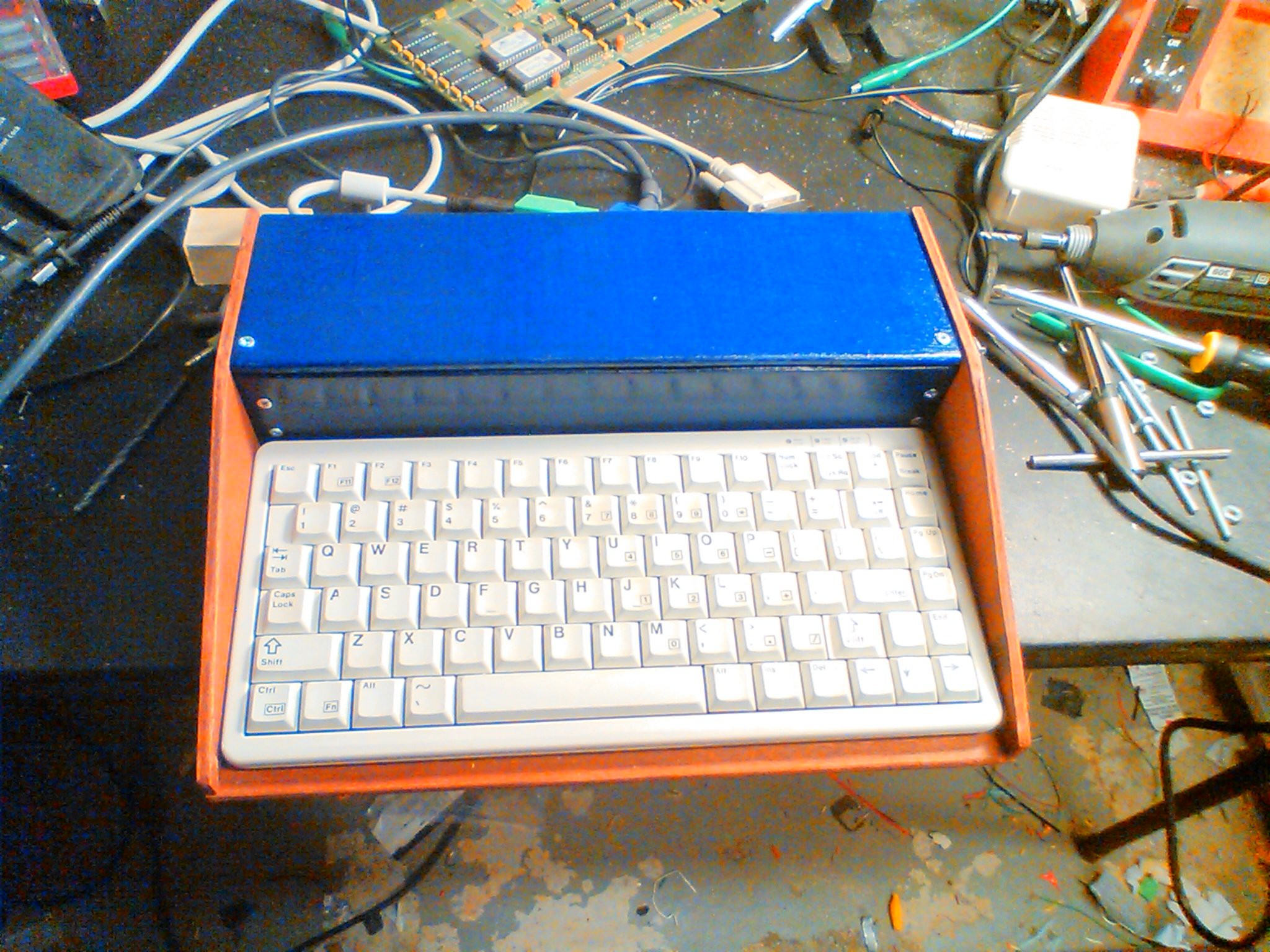
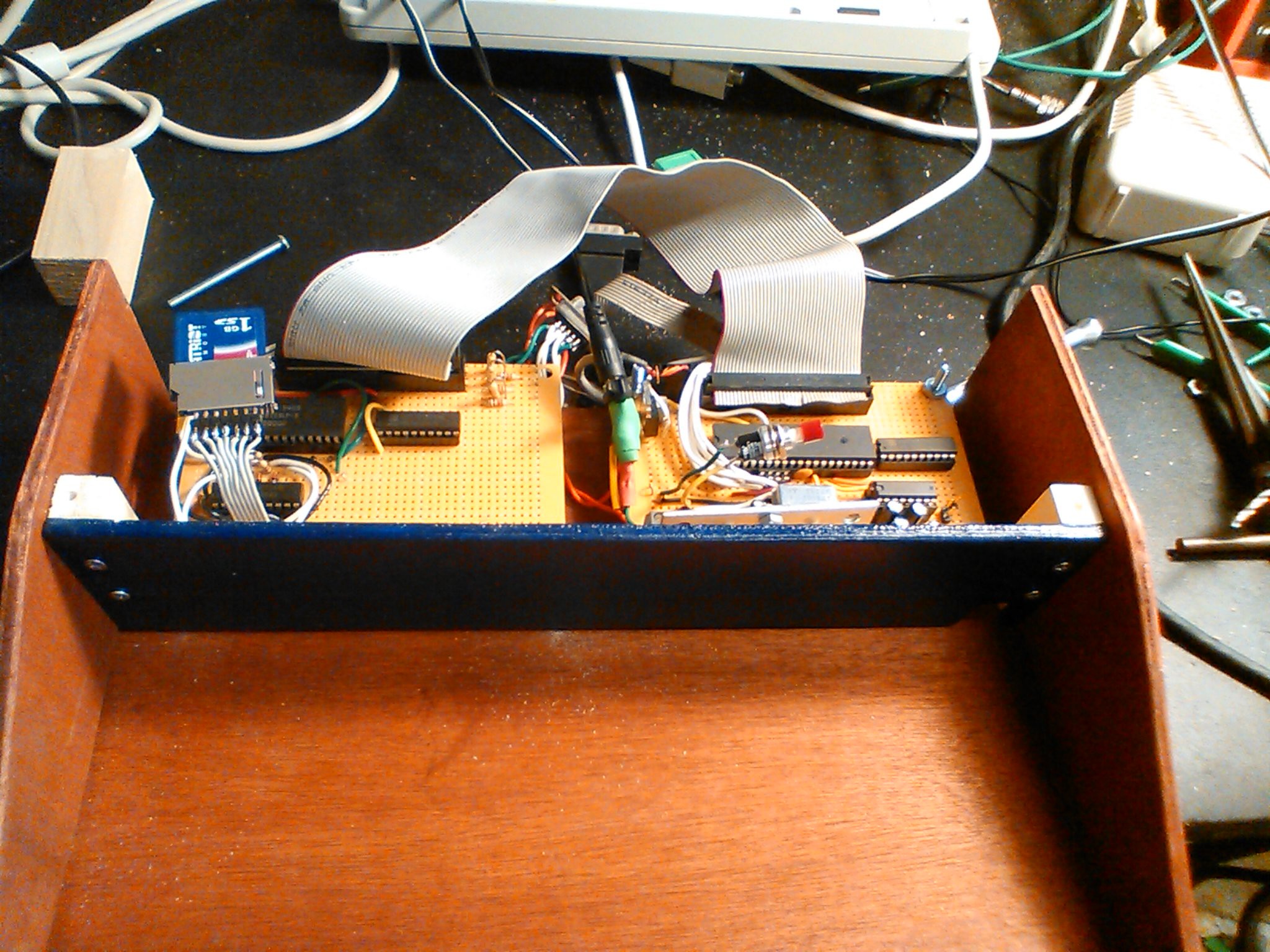
08/21/2014 at 05:20 • 0 commentsAnother real-time update: The Cat-644 is no longer a naked circuit board. The two boards fit side by side inside a compact wooden case. I could have just put the circuit board in a box, and connect it through a KVM to my existing keyboard and screen. Instead, since this is a retro-ish project, I opted to build the classic 80's microcomputer form factor: A computer built into a keyboard.
I thought about the commodore 64, and the smaller Commodore 64c.
Everyone, of course, knows about the wooden cased Apple I.
I took a look online and came across the Sol Terminal Computer.
It all sort of spun together in my head, and what I came up with was pretty simple:
![]()
(Sorry the photo is a little grainy, I took it with my phone.)
![]()
The case was built to just hold a keyboard I already had, one of these Cherry keyboards.
I need to add a slot for the SD card. Or, I could just tie it down inside and treat it as a 'hard drive' and never take it out. For an 8-bit machine, 1GB hard drive might as well be nearly infinite storage space. I always have the serial port to download programs into it. No sneakernet required shuttling sdcards from PC to PC.
After putting it all together and turning it on, typing on it really reminded me of typing on this when I was a kid.
Next steps:
Ethernet: I want to connect to the internet, without the 'help' of a PC. There seems to be two main options: the wiznet chips (like the W5100) and the Microchip ENC28J60
Both use the SPI bus. The ENC28J60 is very simple, so the burden of the TCP stack is pushed into my code: I have to do it or find a library. There are libraries out there, but limited abilities. The Wiznet chip does the TCP stack itself, leaving me with more-or-less a serial interface; once the socket is up I just send/recv bytes to the thing. I was also tempted by the simplicity of a device such as the wiz110sr, which just IS a serial port that connects to a socket. I would put it in a seperate box, call it a 'modem,' and get on with my life.
I didn't want to use-up the only serial port of the ATMega. And I have a 'no surface mount' rule currently in this project. So I opted to use a ready-made Wiz5100 module, which is essentially just the w5100 chip, a 3.3v regulator, and some decoupling capacitors on a board. The exact one I got was intended for Arduino use, but I got it for $16 on clearance because its the 'old version.' (Turns out the new version has an SD card slot, so maybe I could have saved myself some time NOT building my own damned level converter... )
So, I will be using the Wiznet 5100 chip, for now.
What I really want to do later is combine with THIS after he finishes his project: replace serial with a high speed SPI link between the ethernet microcontroller and the Cat-644 MPU.Software: I've been working on cat-os. So far, the 'main' of the program displays some graphics on the screen, and interacts through the keyboard and serial port. I do have sound, sdcard code, and a virtual machine interpreter, as seperate little test programs, but they haven't been integrated in yet. The intention is to integrate them next. Cat-os should start up in a simple shell that lets you navigate the sdcard filesystem, using either the screen and keyboard or the serial port. Then when the user selects a program, that program is loaded and run in the VM interpreter. That's the plan. What's the long term plan? I want an editor, and at least a VM bytecode assembler, running on the Cat. I can't call it a 'true computer,' until I turn it on, sit down in front of it, and write a program on it, eithout the assistance of a modern PC.
Backlog
I still have 1 'backlog' topic: The SD Card. My project runs on 5v, but SDCards like 3.3v. I had to come up with a level shifter, and since I'm a big fan of 'parts on hand' and not waiting for mail order, I whipped up this:
Bye for now...
Well, its almost the Hackaday Prize deadline. What are the last things I want to say before I await judgement: Thanks Hackaday! By jumping into this contest, it really motivated me to get all the documentation drawn up on the computer and put out there on the internet. If I hadn't decided to enter this project, all the notes would still be on paper. And I probably wouldn't have bothered to build the case yet. Even if I loose, it did give me a kick in the butt, and the project will finish a whole hell of a lot faster.
-
Catch-up to realtime
08/11/2014 at 16:44 • 0 commentsI've been writing a 'backlog' of project logs, documenting parts of construction that I did before joining Hackaday.io. There are still a few updates in the backlog, but there is a quick real-time status update.
First: A mess of wires:
![]()
The whole thing is off the breadboard! It's been off the breadboard for a while. The design was originally split into two boards. The bottom board has the CPU, oscillator, rs-232, and the top board has RAM, video and SD card. When I was experimenting, I thought the RAM and video design would change a lot, so I wanted flexibility. I built the CPU board first, and connected it through a ribbon cable (40-wire common 'IDE' cable) to the breadboard. I thought that a ribbon cable would make a good backplane, and the commonly availabile IDE, with 3 connectors, would let me have 3 boards, if I wanted to add lot of expansion. I ended up quickly stabilizing on a simple design, and in retrospect it all would have fit on one board. Any future CAT-644 builds will be single-board, although I will probably keep the ribbon cable to allow for expansion.
I've also been working on a case. I had two ideas for a case. The first, is a simple box. The CAT-644 board(s) can be put in a compact rectangular case. The case would have stanfard PS/2 and VGA connectors on it, and it can just 'live' on a desk, with all the other computers, and even share screen and keyboard through a standard KVM. This is the more practical form factor, and eventually my CAT-644 will end up in a case like that.
But, for now, I really wanted to create a classic 80's 8-bit micro. This means the computer and keyboard all in one box.
-
Keyboard Interrupt Issues
08/09/2014 at 08:32 • 0 commentsThe keyboard caused me a lot of trouble throughout this project. It ended up being re-done twice!
Reading a PS/2 keyboard is fairly straightforward. Here is a snip from my Project Details page:
The PS/2 protocol consists of 2 signals: CLK and DATA. These are on open collector bus running at TTL (5v) levels. Open collector refers to the way the transistor are arranged, but that isn't that important here. What is important are three things:
- CLK and DATA are normally high, due to a pull-up resistor
- Either side (keyboard or host) can drive a line 'low'
- Reading a low value is a definite 0; reading a high value is either a '1' , or the other side is idle
In normal operation, the keyboard controls the clock. Whenever a key is pressed, a scan code is transmitted from the keyboard to the host. One important detail is the DATA is considered valid on the falling edge of the CLK signal. This means, they keyboard puts out a data bit, THEN drops clock. When looking at the clock, when the high-to-low transition occurs, we read the data.
11 bits make up a PS/2 keyboard frame:
- START BIT (must be 0)
- DATA BITS, LSB first (8)
- PARITY (odd)
- STOP BIT (must be 1)
The AVR has a function called the pin-change interrupt, which means when an I/O pin changes state, an interrupt is run. The pin to patch is the PS/2 CLK pin, when that signal starts bouncing up and down, the user has pressed a key. The PS/2 data line is valid when CLK is low, so IF a pin change interrupt has occured AND clk is low, we read the data bit. If we save these bits as we read them, we should get 1 complete keyboard scan code. The code to do this is here:
#define KEY_PORT  PORTA
#define KEY_DDR   DDRA
#define KEY_PIN   PINA
#define KEY_MASK  0b00111111
#define KEY_CLK   0b10000000   /* A7 is connected to PS/2 clock */
#define KEY_DATA  0b01000000   /* A6 is connected to PS/2 DATA */

void key_init()
{

    KEY_DDR &= KEY_MASK;  //keyboard are inputs
    KEY_PORT |= KEY_CLK |KEY_DATA ; //pullup

    //enable interrupt
    PCICR = (1 << PCIE0);  //enable pin change interrupt
    PCMSK0 = (1<<PCINT7);     //enable PCINT7

}

//these are volatile so that non-ISR code reading these values don't asumme they don't change

volatile char keyb_readpos=0;  //written by reader
volatile char keyb_writepos=0; //written by driver
volatile char keyb[KEYB_SIZE];
volatile char keybits=0;
volatile char keybitcnt=0;

ISR (PCINT0_vect)
{

    //if KEY_CLK is low, this was a falling edge

    if (!(KEY_PIN & KEY_CLK))
    {
	//get the data bit, and shift it left 1 for convenience
        char inbit = (KEY_PIN&KEY_DATA)<<1;

	//are we the start bit, and is it zero?
        if (keybitcnt==0)
        {
            if (inbit==0)
                keybitcnt++;
        }
        else if (keybitcnt<9)
        {
	    //are we a data bit?

            keybits = keybits>>1; //shift right all bits-so-far
            keybits |= inbit;   // OR the new bit on the left
            keybitcnt++;
        }
        else if (keybitcnt==9)
	    //are we the parity bit?  (ignore it)
            keybitcnt++;
        else {
	    //i guess we are the stop bit
            if (inbit==128)    //are we a '1'?
            {
		//we have a data byte!

                keyb[keyb_writepos] = keybits;  //write in buffer
                if (keyb_writepos==(KEYB_SIZE-1))
                    keyb_writepos=0;
                else
                    keyb_writepos++;

            }
            //if we got to 'stop bit' and we are not a '1',soemthing went wrong.
	    //reset and try again later
            keybitcnt=0;
        }

    }

}
The above works well, just not when the video interrupt is not running. If the video interrupt IS running, we can still read the keyboard just fine, but the screen sometimes looses sync. Why?
Keyboard re-do:
Trying to read the keyboard while outputting VGA proved problematic. The monitor wants precise timing. If the user presses a key right before the video routine is supposed to run, the keyboard routine will block the VGA routine. I do generate the hsync signal by hardware timers, so the hsync could happen in the right place, but the start of the interrupt routine has now shifted too-late. HSYNC-to-low is done by the timer, but turning HSYNC high, or toggling VSYNC is still done with software. Also, if the video interrupt starts too late, it won't finish in time for the next HSYNC to happen, and the timing will break.
It turns out the PS/2 spec has the answer. (or so I thought at the time)The host (computer) can also send commands to the keyboard. To send a command the host pulls the CLK line now. What the keyboard is supposed to do, is immediately stop transmitting and listen. When the host has finished its command, the keyboard can attempt to resend that last thing the keyboard was sending. The keyboard is supposed to buffer any keystoke the user makes during this time, and send them when it can. Using this, I would pull the PS/2 CLK low before the active video portion of the video frame. During the vertical blank period (where the AVR sends only hsync/vsync signals, and no video), the CLK line was left back to being an input w/ pullup. This worked resonably well... with one of my keyboards. Another keyboard was erratic, and a third keyboard didn't seem to work at all. It seems to all depend on the keyboard's clock timing. If the keyboard's clock is fast enough to send a full code during the vertical blanking... fine. If the keyboard was too slow, it would never successfully send a code before the 'shutup' signal is applied again. But, having 1 keyboard work while processing video was an important milestone.
Keyboard re-re-do:
I needed a way to read the keyboard while processing video. Using the CLK signal as a way to 'shut up' the keyboard wasn't working very well. It turns out, I already have an interrupt firing periodically. The video interrupt fires for every scanline of video... this is at a rate of about 33 kHz. The maximum PS/2 CLK rate is 15 Khz. So... if I look at the PS/2 port at least 30 Khz I should be able to see both the low and high parts of the clock. (Nyquist/Shannon limit)
At the beginning of the video interrupt is a cycle-counting wait that equalizes interrupt latency. At the end of that wait, the value of PORTA (PINA actually) is captured to a variable. At the end of the video scanline interrupt, the captured PINA value is inspected and compared to the previously captured value (from the previous firing of the interrupt) to see 1) if the CLK changed, and 2) if the transition was from high to low. If it was a high-to-low transition, the capured PS/2 DATA value is processed in the same way as done previously in the keyboard interrupt. The video interrupt now handles video, AND polls the keyboard.
There's just one problem: When the video interrupt decides its time to process keyboard code logic, the interrupt takes too long. By the time the keyboard logic in finished, all the registers are popped off the stack, and the interrupt handler returns to wherever the main program was before it fired, we are already past the point of where the next video interrupt would have started. At best, the next line of video is scrambled, at worst the slight variation in sync signaling has broken the monitor's video sync. It's the same problem all over again. What to do?The simple solution is to not restore machine state. Instead of carefully putting the processor back to its pre-interrupt state, we just jump to the top of the interrupt routine, and directly proceed into processing the next video scanline. This only happens when the PS/2 keyboard sends a bit of data... so every time the user presses a key the CPU looses the little bit of time in between a few scanlines... which doesn't even amount to much. Now the keyboard code works with all 3 of my keyboard I've tested, AND causes no interference to the video picture at all.
unsigned char oldclock=1;  //last state of ps2 clock

ISR (TIMER1_COMPA_vect)  //video interrupt (TIMER1 )
{
    unsigned char i;
    unsigned char laddr;
    unsigned char lddr;
    unsigned char ldata;
    unsigned char lctrl;

    asm volatile ("revideo:");

    wait_until(62);  /* Wait until TIMER1 == 62 clocks */

    kp = KEY_PIN;  //capture ps/2 port at regular interval


 /* Output 1 scanline here
    (not put here, since its not important to keyboard function )
*/


   i = kp & KEY_CLK;  /* isolate the CLK bit*/

    if ((!i) && (i != oldclock))  /* If the CLK bit is low, but was high last time, we had a transition*/
    {
        oldclock=i;

        keypoll(kp);  //do keyboard logic, with the captured port value

        while (TCNT1>50);//wait for counter to roll over

        TIFR1 |= (1 << OCF1A); //clear timer interrupt flag  (setting this bit clears the flag)

	/* Note: we have to clear this flag, because otherwise as soon the the video interrupt finally
		returns, it will immediately re-enter because the timer has re-tripped
	*/


        asm volatile ("rjmp revideo"); /* go up to next scanline */

    }


void inline  keypoll(unsigned char portin) {
	/*This is largely the same as the pin change interrupt used for PS/2*/

        char inbit = (portin & KEY_DATA)<<1;

        if (keybitcnt==0)
        {
            if (inbit==0)
            keybitcnt++;
        }
        else if (keybitcnt<9)
        {
            keybits = keybits>>1;
            keybits |= inbit;
            keybitcnt++;
        }
        else if (keybitcnt==9)
        	keybitcnt++;
        else { //cnt is 10 (11th bit of frame)
            if (inbit==128)
            {
                keyb[keyb_writepos] = keybits;  //write in buffer
                if (keyb_writepos==(KEYB_SIZE-1))
                    keyb_writepos=0;
                else
               	    keyb_writepos++;
            }
            keybitcnt=0;
        }

    }
The 'rjmp revideo' is infortunately ugly inline assembly. For whatever reason, when a simple goto was used, gcc tried to be too clever and a lot of the keyboard logic ran before the video logic, completely breaking the video signal.
Nearly the entire video interrupt is written in C, with only small parts in assembly. A lot of care is taken to make sure the assembly output of gcc does what I expect, in the order I expect it, since timing is so important. This process is fairly fragile. What I will probably end up eventually doing, to make sure others that might not have the same version of gcc, is take the assembly output of gcc for this function, beautify and comment it, and use that as the source code for the video interrupt routine.
-
First Video
08/08/2014 at 03:50 • 0 comments![]()
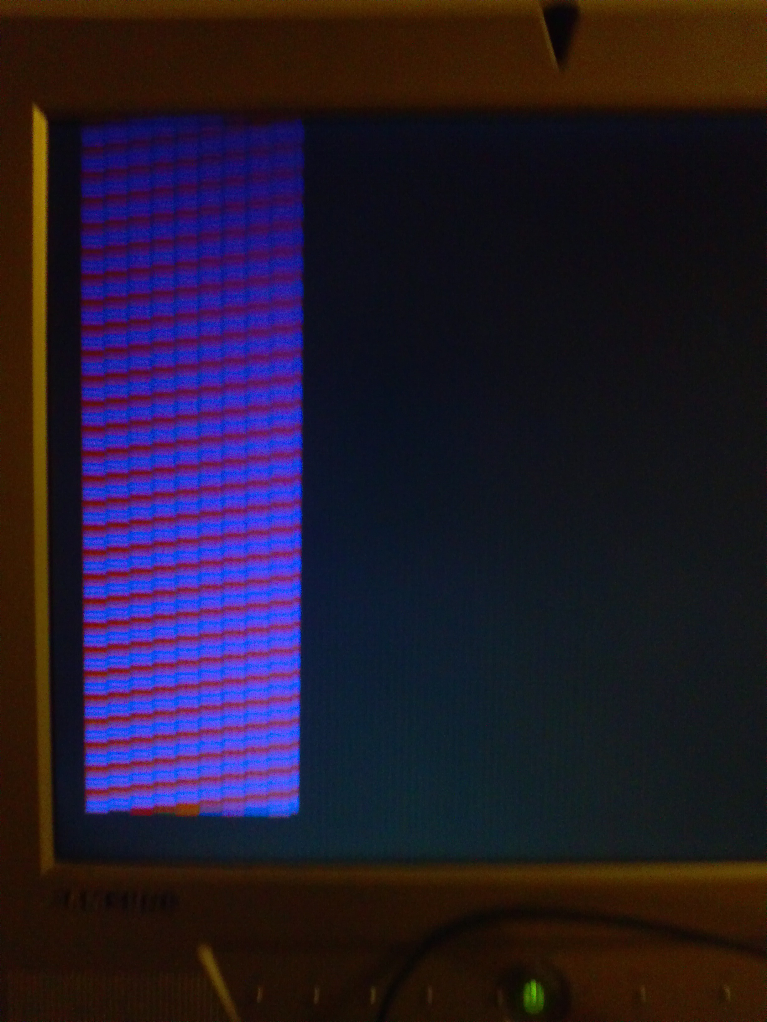
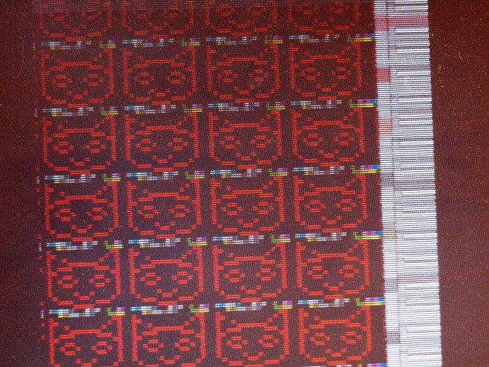
This is the first video signal generated by this project.
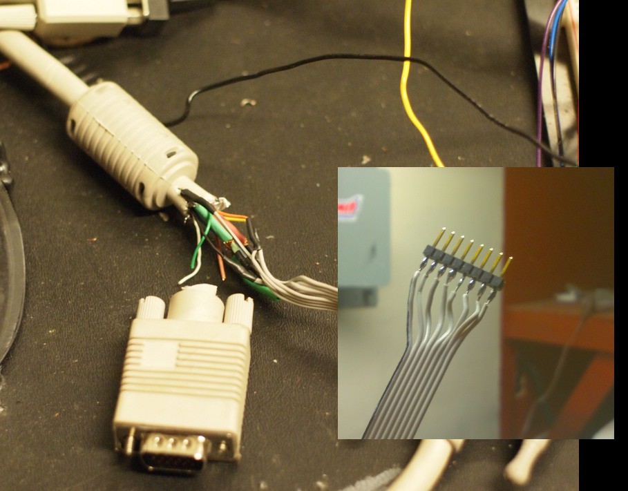
I didn't have a VGA connector laying around, so I cut-up a VGA cable to stick the wires into my breadboard.
![]()
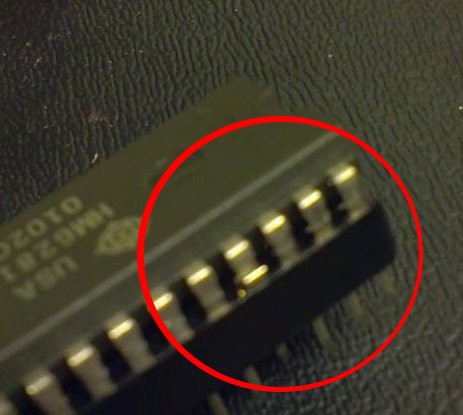
I thought using sockets was a good idea because it would protect the IC against pin damage of the IC being plugged/unplugged into the breadboard. It turns out cheap sockets' pins just push in. This one bad connection cost me several hours.
After proving video generation works, I moved on to displaying a recognizable pattern:
The program that generated the above image, was called cat1.c. The cat1.c program was modified extensively throughout this project to include everything else. When it came time to name this computer, I went with the Cat name.
At this stage of the project, only 8 colors are available. Each color channel it connected thorugh a series resistor and a diode, producing .6 ~ .7 volts when on, which is conveniently close to the 0 to .7v specified in the VGA standard.
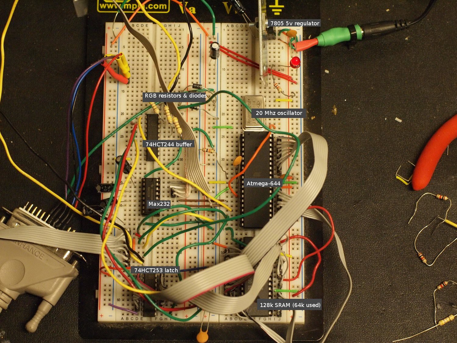
This is the full mess on the breadboard:
-
First Steps
08/06/2014 at 16:28 • 0 comments
USPS package tracking: belmont-> san francisco->oakland->emeryville->oakland->emeryville->oakland
I live in oakland. The mail truck is driving in circles!
----
Well, I have 64k of flash, 4 k of ram and 1mhz 8 bit cpu... blinking an LED.
No dev board kit or arduino babyware, just a raw microcontroller on a protoboard with a self-built programming cable. Next up, 20 mhz external oscillator, and an rs232 port. Actually the max232 chip has 4 level converters in it, so why not, I'll give this 8 bit machine com1 and com2, in an age where you're lucky if your new computer accepts a usb to comm adapter without windows barfing error messages at you.
----
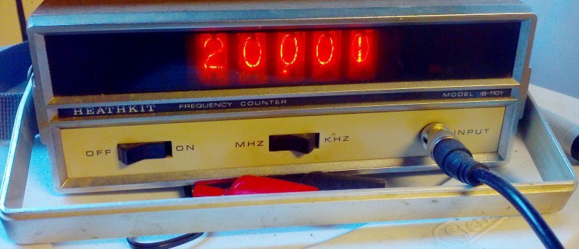
It seems to be working. 20 mhz 8-bit Atmel AVR with 64k flash, 4K sram, currently single rs232 port. The empty socket is where the 128K sram will go. One instruction per clock vs the 6502's 2 clocks per instruction, making this 22 times faster than a 1.8 Mhz Nintendo.![20.001 MHz external clock ( shown on old heathkit freq. counter. )]()
This old Heathkit frequency I got from ebay is proving useful.
![]()
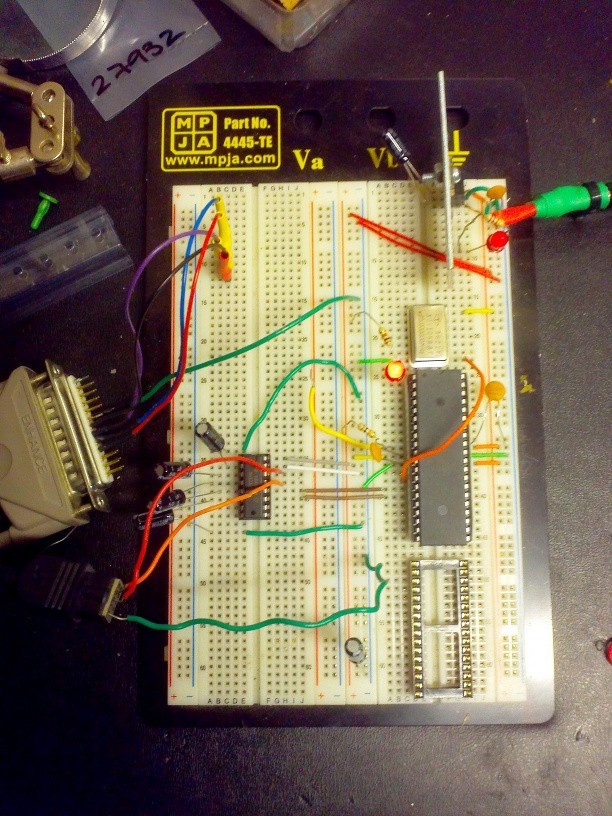
Breadboard:
- Starting from the top right:
- 7805 voltage regulator w/ scrap metal heat sink
- silver can: 20 Mhz crystal oscillator
- Big black chip: AVR Atmega-644
- Empty socket: Placeholder for SRAM
- Left: Max-232 w/ charge pump capacitors
- Far left: Dsub-25 connector that connects to the parallel port of an old PC. When connected to the AVR, the program avrdude, will send a new program over SPI. The 4 wires from the parallel port connect to a header; this head is plugged into port B of the AVR on the breadboard prior to programming. After programming, I plug the header into an unused section of the breadboard to keep it from flopping around.
![]()
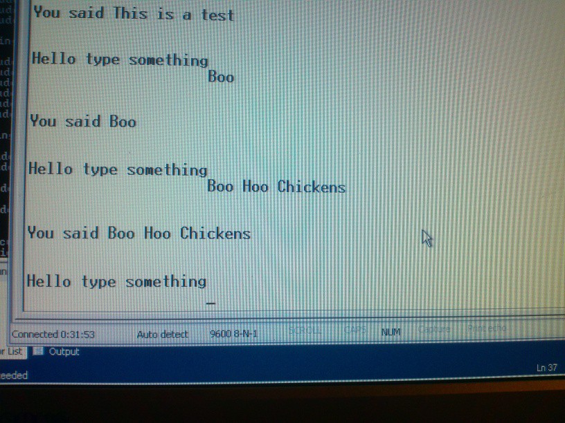
A simple serial test program running over Hyperterminal.
- Starting from the top right:
-
Hello
07/24/2014 at 05:23 • 0 commentsHello
I have been working on this computer project for quite a while. I had not originally intended it as an entry to the Hackaday prize. My original intent was to finish the project, and document the schematics and code online. I saw another couple computer entries entered into the contest, so I figured, if I was going to give away the design anyway, I might as well post it all here, and get a ~ 1/300 chance of blasting off into space.
I'm am going to make a series of posts in the build log, showing from the beginning of the project, what has happened. I've collected notes and pictures along the way, and I will be presenting these in a time-compressed manner.
Why another computer?
I have been playing around with computers since a young kid. One of the first computers I played with was the Commodore Vic-20. It was very limited in its abilities, but it was a start. I eventually got into PCs, and now I'm a software enginner. I've also been very interested in electronics. For a long time, I've been wanting to build my own computer. In college we simulated computers in FPGAs; that's probably the closest to realizing my own computer design in hardware.
Why 8-bit, why AVR?
I wanted to build it myself. 32-bit and 64-bit devices tend to be surface mount with many pins. I also wanted a device that has a lot of support, was reasonably performant, and with fairly modern components. I wanted to use all through-hole parts, making it more likely that others can learn from, copy and modify the design. Large parts of this project can be built, and run, on a breadboard without even soldering anything. Also, I am considering that someday this could be made as a kit, similar to the Uzebox of Maximite kits available online.
When it comes to microcontrollers, there's 2 big camps: the AVR and the PIC. Both are awesome, and come with flash and itty bitty ram, letting you start off right away. Why did I choose AVR? For two reasons. 1) an AVR can execute most instructions single cycle; PIC cannot, and 2)Arduino is AVR-based, and there is a wealth of information about Arduino. If you can connect an Arduino to a whatevery-do, you can connect an AVR to it as well.
Also, before someone mentions it, I do know about the Propeller. It is a 32-bit 8-core DIP chip, has comfortable 32k of RAM, and can generate VGA signals. I did not want to use this, because simply too much of my project is already done for me.
Why VGA and PS/2?
Why not VGA? Most homebrew computers offer either composite video output, OR a simple terminal. I don't want a TV on my desk too! With VGA output, it can use the same monitor my desktop computer uses. With the right KVM, your keyboard too!
Connectivity
Well, this is a connected device competition! There is a lot of inter-device communication going on in this project:
internal:
- bit-bang SRAM interface: don't take RAM for granted. address, page latch, read and write enable, are all controlled by software
external:
- RS-232: The classic interface.
- VGA: mixed analog/digital output with extremely precise timing required
- PS/2 keyboard protocol: Unusual in both software and hardware. A PS/2 keyboard communicates over a clocked, open collector bus, and the clock is generated by the keyboard.
- SD Card interface: SPI bus with level conversion required
- Planned: Ethernet. This is a stretch goal for the project.
Anyone who builds and programs a Cat-644 is going to learn a lot!
Why SD cards?
SD Cards can be put in an SPI mode. Conveniently, AVR microcontrollers have hardware SPI. In SPI mode, SD cards have no minimum data transfer speed, and a maximum speed of 20 or 25 megabits. That is perfect for a 20 MHz system, which may have a very frazzled CPU that needs to slow down. Data is also read/written in blocks of 512 bytes, which very easily fits in the 4k internal RAM of the atmega. I considered compact flash/IDE, but that takes too many I/O lines. USB mass-storage and SATA are too complex and fast for the poor little AVR. There's also SPI flash chips, with which I could build cartridges, but that's pretty much what the SD card already is!
 Mars
Mars