 JF
JFTL;DR I used a ATmega328P (naked, internal oscillator), a battery-backed RTC (DS1307), and 5 gorgeous DL3416/2416 modules (big ones from 1990, small ones from 1984) to show the time in 5 minute increments. All hand wired with 30AWG solid wire, in a laser-cut acrylic case (with red acrylic filter for better contrast on the front). It looks really awesome.
This was my first "real" start-to-finish project, took a while because procrastination, but I had some good encouragement and some help from a good friend.
I don't know if anyone will ever read the project logs, but at least they're quite detailed if anyone wants to use their own displays for something, and hopefully enlightening on some details.
Also it took more than 5 minutes to make.
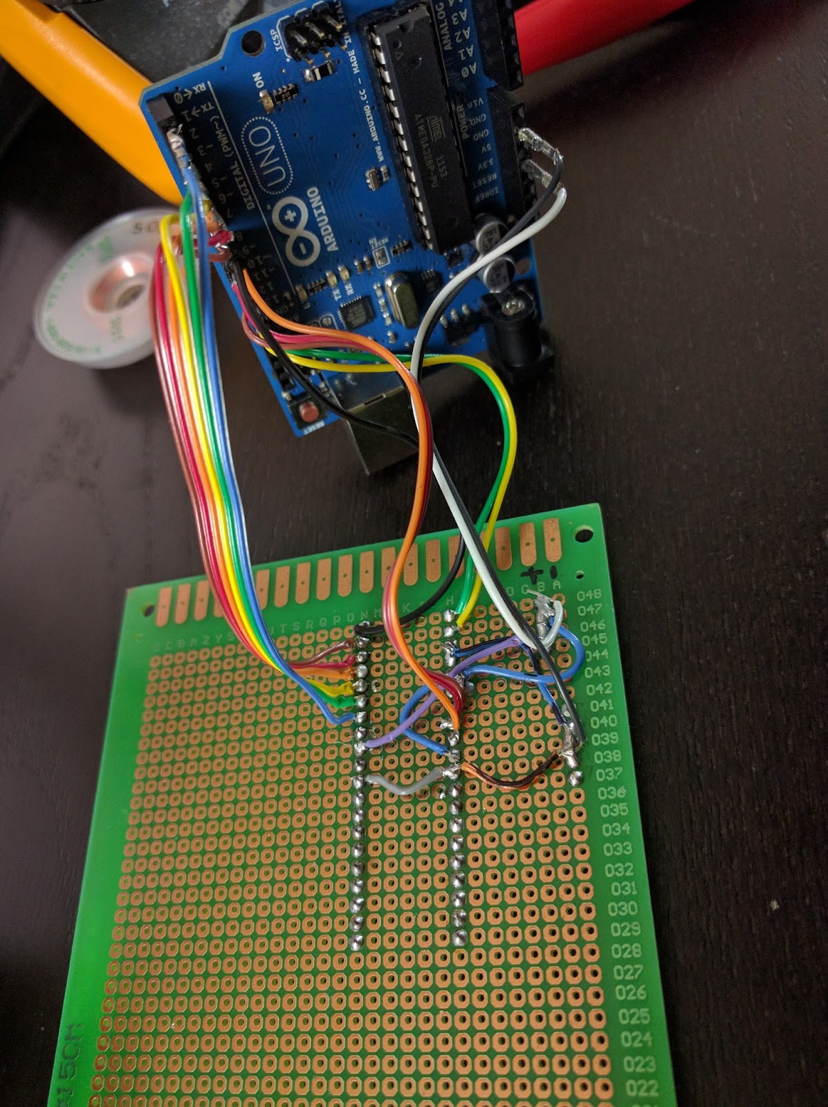
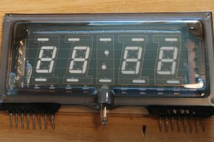
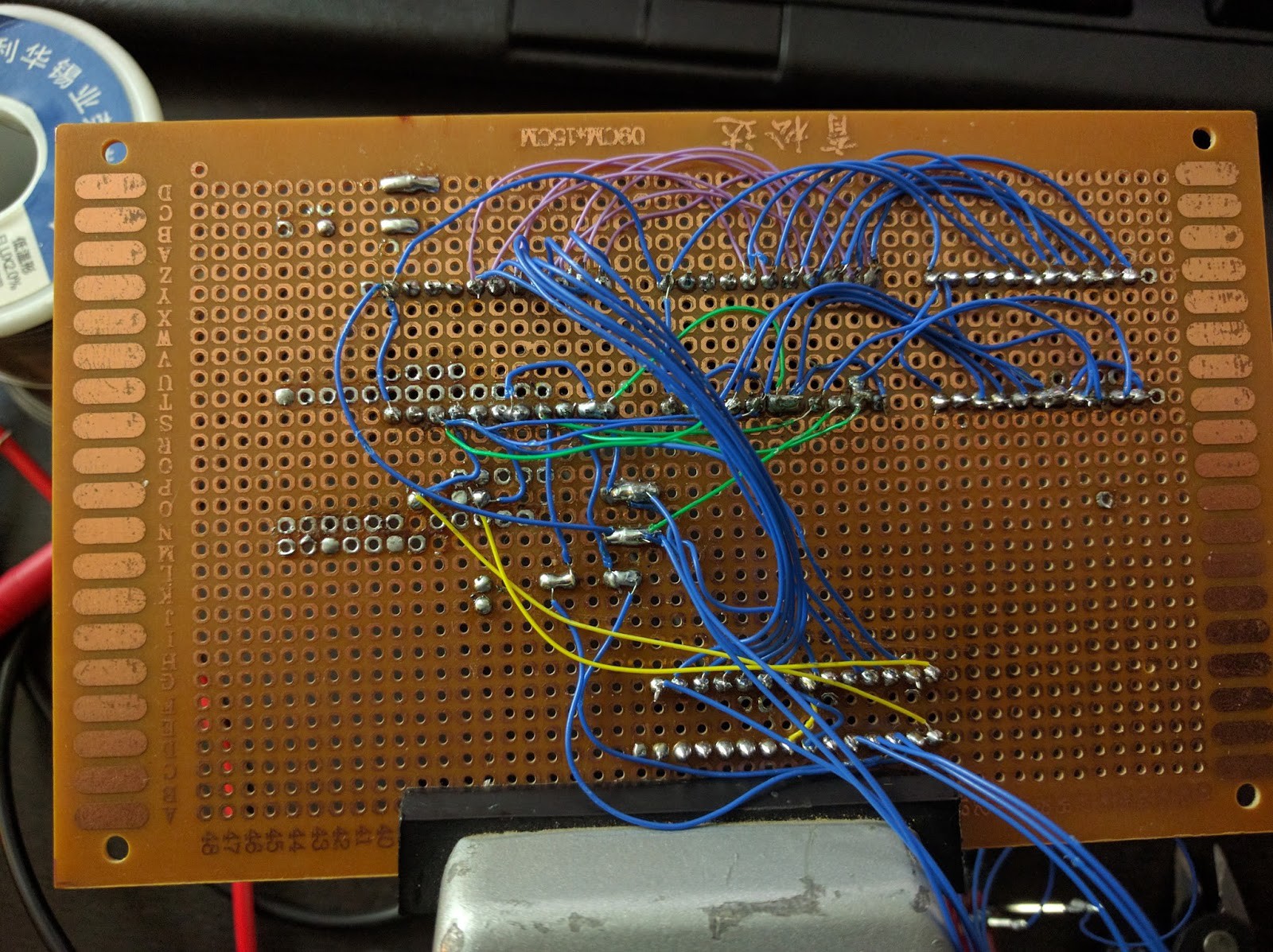 After soldering 3 large modules to the Arduino (note the data bus on top) Small modules not installed yet
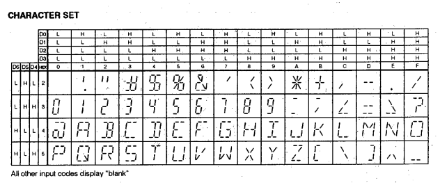
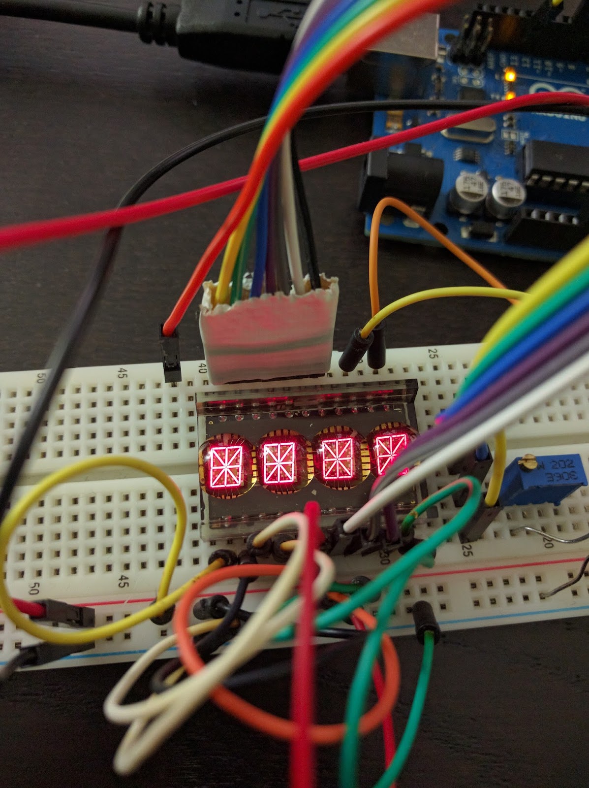
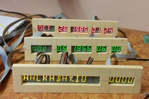
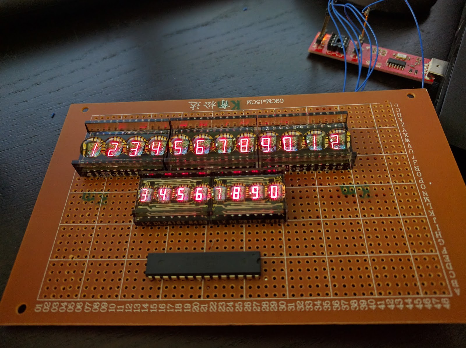 Making sure all the characters are all usable
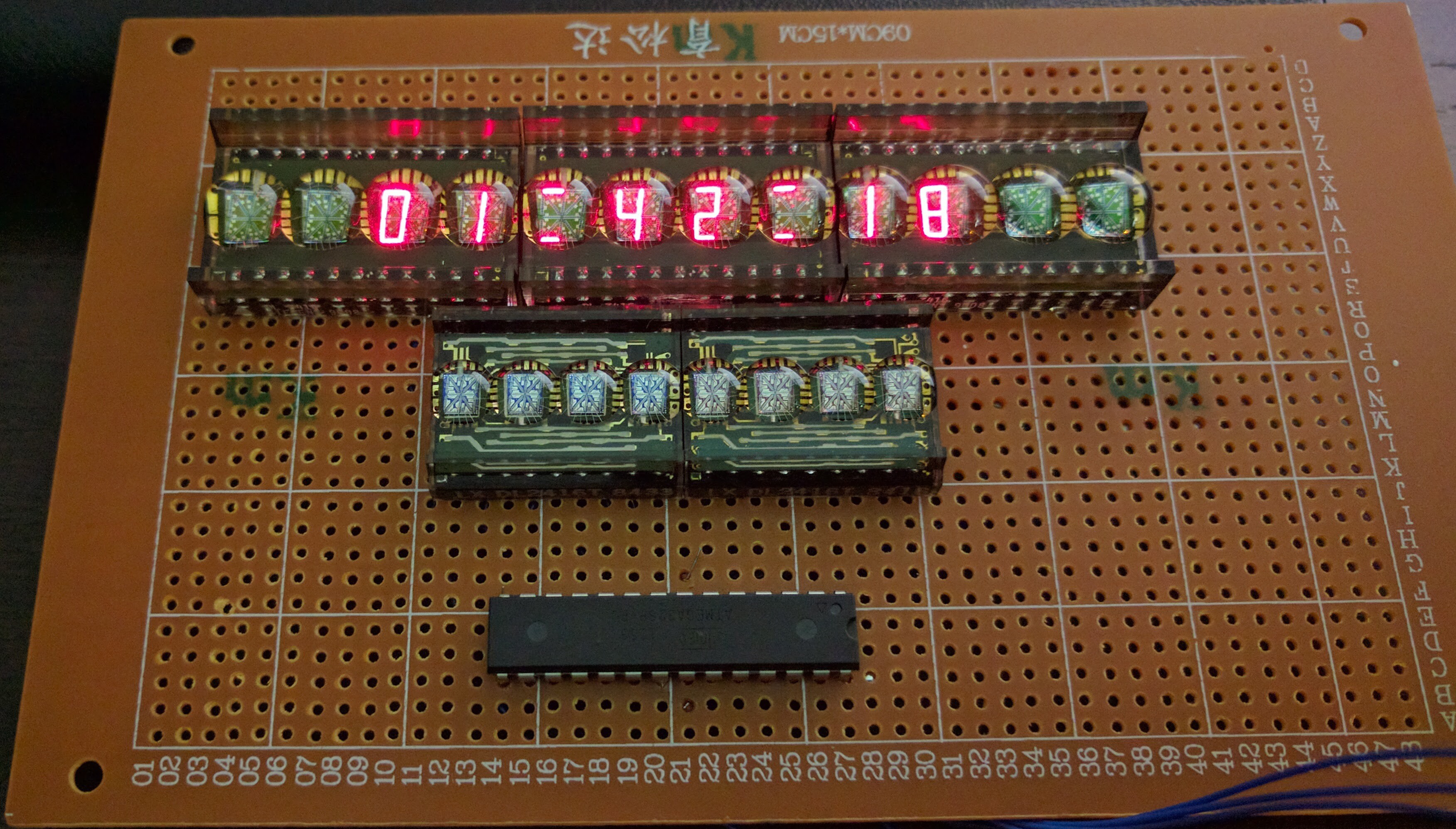 Showing (very drifty) time for the first time! Now let's switch to words.
 This is what the board looks after I mounted the RTC and the filter caps.

 Atheros
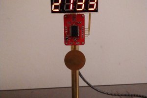
 Pierre-Loup M.
 Brainy.Baboon
That's a beautiful clock! I liked your project so much that I thought maybe I'd give it a go. I have two DL3416's on order (not cheap). But I noticed that your link to the source code is broken. Yeouch! Without that my project is dead in the water. Would you please check the link? Thanks!