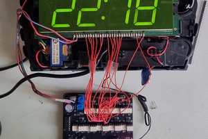
Found this old vfd display in a box a recovered old components, a Noritake FG520A1. The back view shows most of the wiring to the segments. Probing around it was easy to find which was the cathode, while putting 3v to this and grounding the opposite pin, probing the other pins with around 12v enabled me to build up a map of the pins and segments. Not having used one of these before, I thought it might be a simple mapping of segments to pins to switch them on/off. It seems these displays can only address one digit at a time, so it would need some kind of multiplexing and persistence of vision to make them all look to be on at the same time.
I had a couple of Arduino Nanos already, so this was an easy choice of what to use to drive the display. The pins on this work at 5v, so I would need some way of switching the 12v (or more) to the segments. I don't have much electronics experience, but I though some kind of transistor might work for this. A quick search of the net finds lots of similar projects and an idea of transistor type that might work, a BC547. On writing some simple code to switch on all segments from the arduino, nothing displayed. Just cycling through each digit and enabling the segments as fast as possible in sequence did not work. I found that displaying each digit in turn but leaving each lit for a short time worked best. This caused the brightness to drop off a lot. Increasing the anode voltage to around 30v solved the brightness issue when multiplexing the display. It was simply a matter of finding a sweet spot between flickering and brightness. A pause of around 4ms while displaying each digit seemed to work quite well, but I settled on 2ms to make sure there was no flicker, brightness was fine too.
While this worked fine, I came across the ULN2803 darlington transistor array which looked like it might fit nicely with this build, halving the resistor count and making the wiring a little simpler. I have since found there there are also dedicated vfd drivers which make the whole thing far easier, but that's not always the point of these projects.
A DS3231 was used for the realtime clock. I quickly realised I was running out of pins on the arduino. I have used pins 2-15 to address each segment pin on the display, the rtc would have to use pins 18 & 19 (SCA/SCL). Buttons to set the time used pins 2, 16 and 17.
There are quite a few ways to attack the code for displaying the segments and keeping the clock up to date, I opted for just a simple main loop that had the required delays after displaying each digit with an additional check as to whether the clock set button has been pressed, the time spent in this section is short enough not to have an effect on the display. The first button just puts the clock in or out of 'setting' mode. The second increments the current digit, the third button moves to the next digit.


 zst123
 Pierre-Loup M.
 Frederic L
Mmm, VFDs are nearly always muxed due to the number of pins required if you bring out every segment. You only had to search HAD for other projects using VFD for driving information. For example this one: https://hackaday.io/project/9285-russian-vfd-clock or https://hackaday.io/project/27464-yet-another-vfd-tube-clock Some general advice here: https://threeneurons.wordpress.com/vfd-stuff/