 willbaden
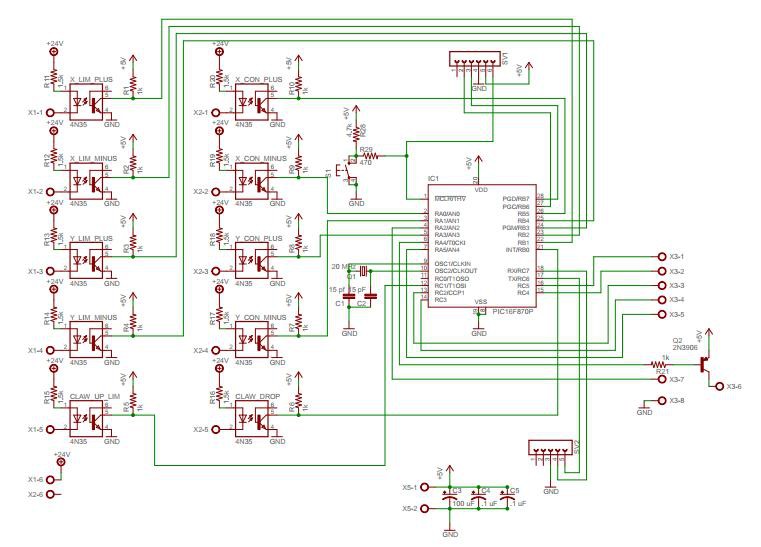
Finally getting to posting the schematic and the board layouts. Here is the microcontroller board that controls the claw machine (schematic):
And the finished board layout:
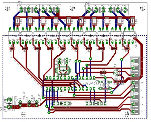
All the inputs from the outside world (joystick control and limits) pass through optocouplers. The resistors selected was 1.5K to allow for 24V DC to be used. The bottom side of the board under the microcontroller was setup as a ground plane while the top side was setup as 5V control power. These planes were not passed under the input (24V) side of the board. Hopefully to reduce any noise that might appear.
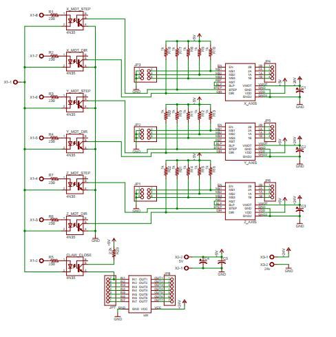
Moving on to the Driver boards, here is the schematic:
And layout:
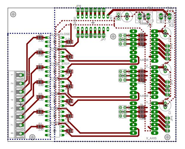
This board was setup to have its inputs also optoisolated. Instead of 24V input voltage, they are setup for 5V input voltage. The reason for isolating the inputs, is so I can use these driver boards in other projects. If I wanted an arduino or parallel port to control them, then I just have to connect up wires and know that they will be isolated. The Drivers themselves require a 5V control and <30V power input. The grounds of these are bonded together and also passed to the bottom side of the board to act as a ground plane. The + supply voltage was then sent to the needed pins without acting as an upper ground plane. Both sides of the optocouplers have isolated planes.
Discussions
Become a Hackaday.io Member
Create an account to leave a comment. Already have an account? Log In.